Design Intelligent Robust Partly Linear Term SMC for Robot Manipulator Systems

Author: AliReza Nabaee, Farzin Piltan, MohammadMahdi Ebrahimi, Mansour Bazregar
Journal: International Journal of Intelligent Systems and Applications(IJISA) @ijisa
Article in issue: 6 vol.6, 2014.
Free access
In this paper the development, modeling and high precision robust control of an electro-mechanical continuum robot manipulator is presented. In this paper main controller is a Sliding Mode Controller which modified by modified PD methodology based on the boundary derivative methodology. Parallel fuzzy logic theory is used to compensate the system dynamic uncertainty controller based on sliding mode theory. Sliding mode controller (SMC) is a significant nonlinear controller under condition of partly uncertain dynamic parameters of system. This controller is used to control of highly nonlinear systems especially for continuum robot manipulator, because this controller is robust and stable in presence of partly uncertainties. PD partly switching nonlinear SMC by modified PD boundary derivative method is used to achieve a stable tracking, while the parallel fuzzy-logic optimization added intelligence to the control system through an automatic tuning of the PD modified partly switching sliding mode methodology uncertainties. Adaptive methodology is used to on-line tuning the sliding surface slope and gain updating factor of this methodology. Simulation results demonstrated the validity of the Mamdani parallel fuzzy-optimization control with asymptotic and stable tracking at different position inputs. This compensation demonstrated a well synchronized control signal at different excitation conditions.
Continuum Robot Manipulator, Parallel Fuzzy-Optimization Control, Robust Control, Sliding Mode Control, Adaptive Methodology, PD Modified Switching Sliding Mode Controller
Short address: https://sciup.org/15010571
IDR: 15010571
Text of the scientific article Design Intelligent Robust Partly Linear Term SMC for Robot Manipulator Systems
Published Online May 2014 in MECS
Email: ,
Continuum robots represent a class of robots that have a biologically inspired form characterized by flexible backbones and high degrees-of-freedom structures [1]. The idea of creating “trunk and tentacle” robots, (in recent years termed continuum robots [1]), is not new [2]. Inspired by the bodies of animals such as snakes [3], the arms of octopi [4], and the trunks of elephants [5-6], researchers have been building prototypes for many years. A key motivation in this research has been to reproduce in robots some of the special qualities of the biological counterparts. This includes the ability to “slither” into tight and congested spaces, and (of particular interest in this work) the ability to grasp and manipulate a wide range of objects, via the use of “whole arm manipulation” i.e. wrapping their bodies around objects, conforming to their shape profiles. Hence, these robots have potential applications in whole arm grasping and manipulation in unstructured environments such as rescue operations.
Theoretically, the compliant nature of a continuum robot provides infinite degrees of freedom to these devices. However, there is a limitation set by the practical inability to incorporate infinite actuators in the device. Most of these robots are consequently underactuated (in terms of numbers of independent actuators) with respect to their anticipated tasks. In other words they must achieve a wide range of configurations with relatively few control inputs. This is partly due to the desire to keep the body structures (which, unlike in conventional rigidlink manipulators or fingers, are required to directly contact the environment) “clean and soft”, but also to exploit the extra control authority available due to the continuum contact conditions with a minimum number of actuators. For example, the Octarm VI continuum manipulator, discussed frequently in this paper, has nine independent actuated degrees-of-freedom with only three sections. Continuum manipulators differ fundamentally from rigid-link and hyper-redundant robots by having an unconventional structure that lacks links and joints. Hence, standard techniques like the Denavit-Hartenberg (D-H) algorithm cannot be directly applied for developing continuum arm kinematics. Moreover, the design of each continuum arm varies with respect to the flexible backbone present in the system, the positioning, type and number of actuators. The constraints imposed by these factors make the set of reachable configurations and nature of movements unique to every continuum robot. This makes it difficult to formulate generalized kinematic or dynamic models for continuum robot hardware. Chirikjian and Burdick were the first to introduce a method for modeling the kinematics of a continuum structure by representing the curve-shaping function using modal functions [6]. Mochiyama used the Serret-Frenet formulae to develop kinematics of hyper-degrees of freedom continuum manipulators [5]. For details on the previously developed and more manipulator-specific kinematics of the Rice/Clemson “Elephant trunk” manipulator, see [1-8]. For the Air Octor and Octarm continuum robots, more general forward and inverse kinematics have been developed by incorporating the transformations of each section of the manipulator (using D-H parameters of an equivalent virtual rigid link robot) and expressing those in terms of the continuum manipulator section parameters. The net result of the work in [3-9] is the establishment of a general set of kinematic algorithms for continuum robots. Thus, the kinematics (i.e. geometry based modeling) of a quite general set of prototypes of continuum manipulators has been developed and basic control strategies now exist based on these. The development of analytical models to analyze continuum arm dynamics (i.e. physicsbased models involving forces in addition to geometry) is an active, ongoing research topic in this field. From a practical perspective, the modeling approaches currently available in the literature prove to be very complicated and a dynamic model which could be conveniently implemented in an actual device’s real-time controller has not been developed yet. The absence of a computationally tractable dynamic model for these robots also prevents the study of interaction of external forces and the impact of collisions on these continuum structures. This impedes the study and ultimate usage of continuum robots in various practical applications like grasping and manipulation, where impulsive dynamics [1-10] are important factors. Although continuum robotics is an interesting subclass of robotics with promising applications for the future, from the current state of the literature, this field is still in its stages of inception.
In modern usage, the word of control has many meanings, this word is usually taken to mean regulate, direct or command. The word feedback plays a vital role in the advance engineering and science. The conceptual frame work in Feed-back theory has developed only since world war ІІ. In the twentieth century, there was a rapid growth in the application of feedback controllers in process industries. According to Ogata, to do the first significant work in three-term or PID controllers which Nicholas Minorsky worked on it by automatic controllers in 1922. In 1934, Stefen Black was invention of the feedback amplifiers to develop the negative feedback amplifier[11-13]. Negative feedback invited communications engineer Harold Black in 1928 and it occurs when the output is subtracted from the input. Automatic control has played an important role in advance science and engineering and its extreme importance in many industrial applications, i.e., aerospace, mechanical engineering and robotic systems. The first significant work in automatic control was James Watt’s centrifugal governor for the speed control in motor engine in eighteenth century[14]. There are several methods for controlling a robot manipulator, which all of them follow two common goals, namely, hardware/software implementation and acceptable performance. However, the mechanical design of robot manipulator is very important to select the best controller but in general two types schemes can be presented, namely, a joint space control schemes and an operation space control schemes[15]. Joint space and operational space control are closed loop controllers which they have been used to provide robustness and rejection of disturbance effect. The main target in joint space controller is design a feedback controller that allows the actual motion ( qn()) ) tracking of the desired motion ( Qd (t) ). This control problem is classified into two main groups. Firstly, transformation the desired motionXd(t) to joint variable qd(t) by inverse kinematics of robot manipulators [16-17]. The main target in operational space controller is to design a feedback controller to allow the actual end-effector motion Xa(t) to track the desired endeffector motion Xd(t) . This control methodology requires a greater algorithmic complexity and the inverse kinematics used in the feedback control loop. Direct measurement of operational space variables are very expensive that caused to limitation used of this controller in industrial robot manipulators[18-26]. One of the simplest ways to analysis control of multiple DOF robot manipulators are analyzed each joint separately such as SISO systems and design an independent joint controller for each joint. In this methodology, the coupling effects between the joints are modeled as disturbance inputs. To make this controller, the inputs are modeled as: total velocity/displacement and disturbance. Design a controller with the same formulation and different coefficient, low cost hardware and simple structure controller are some of most important independent-joint space controller advantages. Nonlinear controllers divided into six groups, namely, feedback linearization (computed-torque control), passivity-based control, sliding mode control (variable structure control), artificial intelligence control, Lyapunov-based control and adaptive control[27-40]. Sliding mode controller (SMC) is a powerful nonlinear controller which has been analyzed by many researchers especially in recent years. This theory was first proposed in the early 1950 by Emelyanov and several co-workers and has been extensively developed since then with the invention of high speed control devices. The main reason to opt for this controller is its acceptable control performance in wide range and solves two most important challenging topics in control which names, stability and robustness [41-59]. Sliding mode controller is divided into two main sub controllers: discontinues controller (TjiS) and equivalent controller(Te(Z). Discontinues controller causes an acceptable tracking performance at the expense of very fast switching. Conversely in this theory good trajectory following is based on fast switching, fast switching is caused to have system instability and chattering phenomenon. Fine tuning the sliding surface slope is based on nonlinear equivalent part [50-59]. However, this controller is used in many applications but, pure sliding mode controller has two most important challenges: chattering phenomenon and nonlinear equivalent dynamic formulation in uncertain parameters[55-59]. Chattering phenomenoncan causes some problems such as saturation and heats the mechanical parts of robot manipulators or drivers. To reduce or eliminate the chattering, various papers have been reported by many researchers which classified into two most important methods: boundary layer saturation method and estimated uncertainties method [20-45]. In recent years, artificial intelligence theory has been used in nonlinear control systems. Neural network, fuzzy logic and neuro-fuzzy are synergically combined with nonlinear classical controller and used in nonlinear, time variant and uncertain plant (e.g., robot manipulator). Fuzzy logic controller (FLC) is one of the most important applications of fuzzy logic theory. This controller can be used to control nonlinear, uncertain, and noisy systems. This method is free of some model techniques as in model-based controllers. As mentioned that fuzzy logic application is not only limited to the modelling of nonlinear systems [15-59] but also this method can help engineers to design a model-free controller. Control robot arm manipulators using model-based controllers are based on manipulator dynamic model. These controllers often have many problems for modelling. Conventional controllers require accurate information of dynamic model of robot manipulator, but most of time these models are MIMO, nonlinear and partly uncertain therefore calculate accurate dynamic model is complicated [32-37]. The main reasons to use fuzzy logic methodology are able to give approximate recommended solution for uncertain and also certain complicated systems to easy understanding and flexible. Fuzzy logic provides a method to design a model-free controller for nonlinear plant with a set of IF-THEN rules [35-49].
This method is based on design modified fuzzy PD partly linear switching SMC controller and resolves the uncertainty term and chattering phenomenon by fuzzy logic methodology. To have the best performance modified PD method based on boundary derivative methodology is design. The first time coefficients are calculated by Gradient Descent Optimization and to tune the fuzzy logic gain updating factor as well as improve the output performance the on-line tuning algorithm is introduced. To compensate the continuum robot manipulator system’s dynamic, 49 rules parallel Mamdani fuzzy inference system is design and applied to sliding mode methodology with switching highly stable function. The chattering is eliminating, because SMC and FLM work parallel.
This paper is organized as follows; second part focuses on the modeling dynamic formulation based on Lagrange methodology, fuzzy logic methodology, Gradient Descent Optimization and sliding mode controller to have a robust control. Third part is focused on the methodology which can be used to reduce the error, increase the performance quality and increase the robustness and stability. Simulation result and discussion is illustrated in forth part which based on trajectory following and disturbance rejection. The last part focuses on the conclusion and compare between this method and the other ones.
-
II. T heory
Dynamic Formulation of Continuum Robot: The Continuum section analytical model developed here consists of three modules stacked together in series. In general, the model will be a more precise replication of the behavior of a continuum arm with a greater of modules included in series. However, we will show that three modules effectively represent the dynamic behavior of the hardware, so more complex models are not motivated. Thus, the constant curvature bend exhibited by the section is incorporated inherently within the model. The mass of the arm is modeled as being concentrated at three points whose co-ordinates referenced with respect to (see Fig 1);
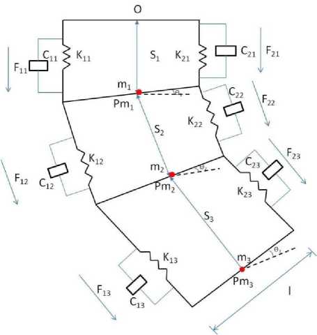
Fig. 1. Assumed structure for analytical model of a section of a continuum arm
Where;
I - Length of the rigid rod connecting the two struts, constant throughout the structure, krд , i = 1,2,3 - Spring constant of actuator 1 at module i, k2,/ , i = 1,2,3 - Spring constant of actuator 2 at module ,
C;,i , i = 1,2,3 - Damping coefficient of actuator 1 at module ,
C2 ,/ , i = 1,2,3 - Damping coefficient of actuator 2 at module ,
, = 1,2,3 - Mass in each module,
, = 1,2,3 - Moment of inertia of the rigid rod in each module.
A global inertial frame (N) located at the base of the arm are given below mi? = St^(1)
„^P = S2. 5 in0tn + (St + S2 с о s в t). n3
m3p = №. 5in#t + S3. sin( 01 +
02)) n3 + (St + S2 соs 01 + S3. соs( 01 + e г ))).n
The position vector of each mass is initially defined in a frame local to the module in which it is present. These local frames are located at the base of each module and oriented along the direction of variation of coordinate 's ’ of that module. The positioning of each of these masses is at the centre of mass of the rigid rods connecting the two actuators. Differentiating the position vectors we obtain the linear velocities of the masses. The kinetic energy (T) of the system comprises the sum of linear kinetic energy terms (constructed using the above velocities) and rotational kinetic energy terms due to rotation of the rigid rod connecting the two actuators, and is given below as
т =(о.5) тг ̇/+(О.5) 7712 (( ̇ 28(пв! + ̇ ч2 Z
S2COS0^6 *1)+( ̇1+ ̇ 2СО80! - 828(116! ̇ ^))+(о.5) 7713 (( ̇ 28(пб! +
̇ + ̇ ( +)+
( + ) ̇ + (+
) ̇ )+( ̇ + ̇ - ̇+
̇ ( + )- ( + ) ̇-
( + ) ̇ ))+( . ) ̇+
(О.5)^2 ( ̇*12 + ̇ *22)+(О.5)/3 ( ̇*12 +
̇ >22 + ̇ -з2).
|
Qs3 = + F23 |
(9) |
|
Q61 =(1⁄2)( F11 - F21 )+(1⁄2)( F12 - |
(10) |
|
F 22 )+(1⁄2)( F13 - F23 )+ 828(1162 ( F13 + f 23) Q61 =(⁄2)( F12 - F 22 ) |
(11) |
|
+(1⁄2)( F13 - F 23 ) Q61 =(1⁄2)(^13 - F 23 ) |
(12) |
It can be evinced from the force expressions that the total input forces acting on each module can be resolved into an additive component along the direction of extension and a subtractive component that results in a torque. For the first module, there is an additional torque produced by forces in the third module.
The model resulting from the application of Lagrange’s equations of motion obtained for this system can be represented in the form
Fcoeff X =( q ) ̈ + c ( q ) ̇ + g ( q ) (13)
The potential energy (P) of the system comprises the sum of the gravitational potential energy and the spring potential energy. A small angle assumption is made throughout the derivation. This allows us to directly express the displacement of springs and the velocities associated with dampers in terms of system generalized coordinates.
Р =- m^S! - m2g ( Si + S2COSd! )- (5)
m3g ( Si + S2COSd! + S3COS ( e^ + e^ ))+ (О.5) ku (Si+(1/2) 6i - sc)2+ (О.5)fc2i (Si+(1⁄2) 9i - Sqi )2+ (О.5)fci2 ( s2 +(1⁄2) 02 - S02 )2+ (О.5)^22 ( s2 +(1⁄2) 02- s02 )2+ (О.5)^13 (S3+(1⁄2) 93 - 5 03 )2+ (О.5)^23 (S3+(1⁄2) 63 - S03 )2
where T is a vector of input forces and q is a vector of generalized co-ordinates. The force coefficient matrix Fcoeff transforms the input forces to the generalized forces and torques in the system. The inertia matrix, D is composed of four block matrices. The block matrices that correspond to pure linear accelerations and pure angular accelerations in the system (on the top left and on the bottom right) are symmetric. The matrix C contains coefficients of the first order derivatives of the generalized co-ordinates. Since the system is nonlinear, many elements of C contain first order derivatives of the generalized co-ordinates. The remaining terms in the dynamic equations resulting from gravitational potential energies and spring energies are collected in the matrix G . The coefficient matrices of the dynamic equations are given below,
where, "Sqi , Sq2 , S03 are the initial values of ST , 53 , S3 respectively.
Due to viscous damping in the system, Rayliegh’s dissipation function [6] is used to give damping energy
D =(О.5) Сц ( ̇!+(1/2) ̇ •i)2+ (6)
(О.5)C21 ( ̇1+(1/2) ̇*i)+(О.5) c12 ( ̇2+ (1/2) ̇*2)+(О.5) C22 ( ̇2+(1/2) ̇*2)+ (О.5)c13 ( ̇3+(1/2) ̇*3)+(О.5) c23 ( ̇3+ (1/2) ̇ *3 )2.
The generalized forces in the system corresponding to the generalized co-ordinates are expressed as appropriately weighted combinations of the input forces.
=
|
⎡1 |
1 |
(0i) |
(0i) |
(0i + 02) |
(01 + 02) |
|
⎢0 |
0 |
1 |
1 |
( 9з) |
(02) |
|
⎢0 |
0 |
0 |
0 |
1 |
1 |
|
⎢⎢ 1⁄2 |
-1⁄2 |
1⁄2 |
-1⁄2 |
1⁄2+ s^sin ( 9з) |
-1⁄2+ s^sin ( 9г) |
|
⎢⎢ 0 |
0 |
1⁄2 |
-1⁄2 |
1⁄2 |
-1⁄2 |
|
⎣0 |
0 |
0 |
0 |
1⁄2 |
-1⁄2 ⎦ |
D(я)=
|
⎡ + + |
m2cos(61) + (Si) |
( 61 + 62 ) |
- (61) - ( 61 ) - (61 + 62) |
- (61 + 62 ) ⎤ ⎥⎥ |
|
⎢ m2cos (6i) ⎢+ macos (61) |
+ |
m3cos(6?) |
-m3s3sin(6? ) |
⎥ -m3s3sin(62) |
|
m3cos(61 + 6?) |
m3cos(6?) |
m3 |
m3s3sin(6?) |
⎥⎥ |
|
⎢-m2s2sin(61) -m3s2sin(61) -m3s3sin(61 + 6? ) |
- (6?) |
m3s2sin(6?) |
+ + + + + + (6?) |
⎥⎥ + + ⎥ +m3s3cos(62 ) ⎥ |
|
⎢ -m3s3sin( + ) |
- (6?) |
0 |
+ + +m3s3cos(6?) |
⎥ + + ⎥ |
|
⎣ |
0 |
0 |
1. |
⎦ |
Q$i = + ^21 +( F12 + F22 ) СО8б! + (7)
( F13 + F23 ) cos ( 9i + 92 )
Qs2 = + F22 +( F13 + F23 ) cos ( ®2 ) (8)
|
c(я)= |
- |
(16) |
|||
|
⎢⎡ ⎢-2mzsin(6i) ̇ ⎢⎢ + -2m3sin(Si) ̇ ⎢⎢ |
- (6i + 62) ( ̇+ ̇) |
(6i)( ̇ ) +(⁄)( + ) - ( 6i)( ̇ ) - (6i + 62)( ̇ ) |
- (61 + 62) |
⎤ |
⎥⎥⎥⎥⎥⎥ |
|
⎢⎢ ⎢⎢ ⎢ 0 c12 + ⎢ ⎢ ⎢⎢ |
- (62 ) ( ̇+ ̇) |
- ( ̇ ) +(⁄) ( + ) - ( ̇ ) - (62)( ̇ ) |
- (62)( ̇ ) - (62)( ̇ ) |
⎥⎥⎥⎥⎥⎥⎥⎥⎥ |
|
|
⎢⎢ ⎢ 0 2m3sin(62)( ̇ ) |
+ |
- (62)( ̇ ) - ( ̇ ) |
- ( ̇ ) - ( ̇ ) |
(1⁄2) ( + ) |
⎥⎥⎥⎥ |
|
⎢(⁄) 2m3s3cos(62)( ̇ ) ⎢(⁄) ⎢( + ) - ( ̇ ) ⎢⎢ + ( ) |
( ̇+ ̇) - (62) ( ̇ + ̇ ) |
2m3s3s3 (62)( ̇ ) +( ⁄ ) ( + ) |
(62)( ̇ ) |
⎥⎥⎥⎥⎥⎥ |
|
|
⎢⎢ ( ⁄ )( + )+ ⎢ 2m3s3cos(62)( ̇ ) |
( ̇ + ̇ ) |
(62) ( ̇ ) |
( ⁄ ) ( + ) |
⎥⎥⎥ |
|
|
⎢ ⎣⎢ |
(⁄)( - ) |
0 |
0 |
( ⁄ ) ( + )⎦ |
⎥ |
G(q)=
⎡- - + kn($i+( ⁄ )Si- )+^21(Si-( ⁄ )Si-)-
⎡⎤
⎢- m2gcos ( 91 )+^12 ($2+( ⁄ )e2- )+^22($2-( ⁄ )e2- )- m3gcos ( 9i )⎥
⎢ - ( + )+ ( +(⁄) - )+ ( -(⁄) - )⎥
⎢⎥
⎢ m2 S2gsin ( 91 )+ m3s3gsin ( 9i + 9г )+ m3s2gsln ( 9i )+An( +(⁄) 9i - )( ⁄ )⎥
⎢⎢ + ,£21(Si-( ⁄ )9i - )(- ⁄ )
⎢⎥
⎢ m3s3gsin ( 9i + e2 )+ ( +(⁄) e2 - )(⁄)+ ( -(⁄) e2 - )(- ⁄)⎥
⎢⎥
⎣ ( +(⁄)e3 - )(⁄)+ ( -(⁄)e3 - )(- ⁄)⎦
Sliding Mode Controller and prove the stability: Consider a nonlinear single input dynamic system is defined by [6]:
X ( ) = f ( ⃗ ⃗) + b ( ⃗ ⃗) и (18)
Where u is the vector of control input, X ( ) is the nth derivation of X , X =[ X , ̇, ̈,…, X ( n—1)] T is the state vector, /( X ) is unknown or uncertainty, and b ( X ) is of known sign function. The main goal to design this controller is train to the desired state; Xd =[ Xd , ̇ *d , ̈ *d ,…, Xd ( n—1)] T , and trucking error vector is defined by [6]:
̃= X - xd =[̃,…, ̃( n-1 ) ] T (19)
A time-varying sliding surface s ( X , t ) in the state space Rn is given by [6]:
S ( X , t )=(^ +Я) n-l ̃= 0
where λ is the positive constant. To further penalize tracking error, integral part can be used in sliding surface part as follows [6]:
1 d(22)
2^t$2 (X,t)≤- < |S(X,t )| where ζ is positive constant.
If S(0)>0→ Ss(t)≤-<
To eliminate the derivative term, it is used an integral term from t=0 to t= breach
∫ =o (t)≤-∫:=0^ →
S( breach )- S (0)≤-<( breach -0)
Where breach. is the time that trajectories reach to the sliding surface so, suppose S( breach =0) defined as;
s ( 0 )
0-S(0)≤-4( breach )→ breach ≤
and
IfS (0)<0→0-5(0)≤-4( breach )→ (26)
S (0)≤-<( breach )→ breach ≤ | - ( “ )|
Equation (26) guarantees time to reach the sliding surface is smaller than | ( )| since the trajectories are outside of 5(t).
^ ^^reach =(0)→error (x- Xd)=0
suppose S is defined as
S(X,t)=( +A) ̃=( ̇- ̇:d)+
A(x- Xd )
The derivation of S, namely, ̇ can be calculated as the following;
̇=( ̈- ̈d)+A( ̇- ̇d )
suppose the second order system is defined as;
̈=f+U→ ̇=f+U- ̈d(30)
+A( ̇- ̇d)
Where f is the dynamic uncertain, and also since s =0 and S ̇=0, to have the best approximation , ̂ is defined as
S( X , t )=( +я) n-l
(∫ ̃ dt )= 0
̂=- ̂+ ̈ *d - A ( ̇- ̇d)
The main target in this methodology is kept the sliding surface slope S( X , t ) near to the zero. Therefore, one of the common strategies is to find input U outside of S ( X , t ) [6].
A simple solution to get the sliding condition when the dynamic parameters have uncertainty is the switching control law [52-53]:
и dis = и- K°r, t) • s gn(s)
where the switching function sgn(S) is defined as [1, 6]
( 1 s > 0
sgn (s) —{-1s<0
(0s = 0
and the K(x, t) is the positive constant. Suppose by (22) the following equation can be written as,
1 d x r ,(34)
(x, t) — S • S — [f - / - Ksgn(s)] • 5 = (f-f)-S-K|S| and if the equation (26) instead of (25) the sliding surface can be calculated as
s(r, t) — (^ + A)2 (j" 0 x dt) — (35)
(X - xd) + 2 A(X - xd) - Л2(х - xd)
in this method the approximation of U is computed as [6]
U — —f + X d — 2Л(х — X d )
+ A2(x-X d )
Based on above discussion, the sliding mode control law for a multi degrees of freedom robot manipulator is written as [1, 6]:
the dynamic equation of robot manipulator can be written based on the sliding surface as
MS — -KS + MS + B + C+ G it is assumed that
ST (M -2 В + C + G)S — 0
by substituting (43) in (44)
K — 1—T MS - STВ + CS + ST(MS + В + CS +
G) — ST(MS + В + CS + G)
suppose the control input is written as follows
P— U^etIr + ^— [^(B+C+G)+
—]й + К. sg n(S) + В + CS + G by replacing the equation (49) in (41)
K — ST(MS + B + C + G-MS- BTCS + G -
Ksgn(S) — ST (MS + B + CS + G - Ksgn(S))
and
|MS + ^+CS + G| < |MS| + |^+CS + G| the Lemma equation in robot arm system can be written as follows
T T eq + ^dls
Ku — [|MS| + |В + CS + G| + q]( ,i — 1,2,3,4,™ (49)
Where, the model-based component Te q is the nominal dynamics of systems calculated as follows [1]:
Teq — [O-1(f + C + G)+S]O and Tdis is computed as [1];
Tdis — К • sgn(5)
By (39) and (38) the sliding mode control of robot manipulator is calculated as;
t — [B-1(f + C + G) + S]B + K • sgn(S)
where 5 — Ae + e in PD-SMC and 5 — Ae + e + ( | )2 Ze inPID-SMC.
The lyapunov formulation can be written as follows,
and finally;
Р<-^тв№1 i=l
Linear Controller: In the absence of robot knowledge, proportional-integral-derivative (PID), proportionalintegral (PI) and proportional -derivative (PD) may be the best controllers, because they are model-free, and they’re parameters can be adjusted easily and separately [1] and it is the most used in continuum robot manipulators. In order to remove steady-state error caused by uncertainties and noise, the integrator gain has to be increased. This leads to worse transient performance, even destroys the stability. The integrator in a PID controller also reduces the bandwidth of the closed-loop system. PD control guarantees stability only when the PD gains tend to infinity, the tracking error does not tend to zero when friction and gravity forces are included in the continuum robot manipulator dynamics [2]. Model-based compensation for PD control is an alternative method to substitute PID control [1], such as adaptive gravity compensation [3], desired gravity compensation [2], and PD+ with position measurement [4]. They all needed structure information of the robot gravity. Some nonlinear PD controllers can also achieve asymptotic stability, for example PD control with time-varying gains [5], PD control with nonlinear gains [6], and PD control with feedback linearization compensation [8]. But these controllers are complex; many good properties of the linear PID control do not exist because these controllers do not have the same form as the industrial PID. Design of a linear methodology to control of continuum robot manipulator was very straight forward. Since there was an output from the torque model, this means that there would be two inputs into the PID controller. Similarly, the outputs of the controller result from the two control
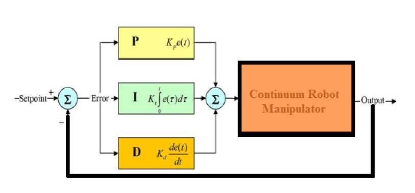
Fig. 2. Block diagram of linear PID method
inputs of the torque signal. In a typical PID method, the controller corrects the error between the desired input value and the measured value. Since the actual position is the measured signal. Fig 2 shows linear PID methodology, applied to continuum robot manipulator [9-16].
e(t) = Oa(t) - 0d(t)
UPID = KPa е*Куа e +K^e
The model-free control strategy is based on the assumption that the joints of the manipulators are all independent and the system can be decoupled into a group of single-axis control systems [14-16]. Therefore, the kinematic control method always results in a group of individual controllers, each for an active joint of the manipulator. With the independent joint assumption, no a priori knowledge of robot manipulator dynamics is needed in the kinematic controller design, so the complex computation of its dynamics can be avoided and the controller design can be greatly simplified. This is suitable for real-time control applications when powerful processors, which can execute complex algorithms rapidly, are not accessible. However, since joints coupling is neglected, control performance degrades as operating speed increases and a manipulator controlled in this way is only appropriate for relatively slow motion
[13-16]. The fast motion requirement results in even higher dynamic coupling between the various robot joints, which cannot be compensated for by a standard robot controller such as PID [16], and hence model-based control becomes the alternative.
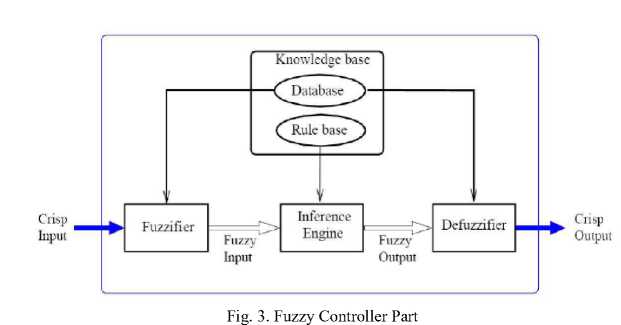
Fuzzy Logic Methodology: Based on foundation of fuzzy logic methodology; fuzzy logic controller has played important rule to design nonlinear controller for nonlinear and uncertain systems [53]. However the application area for fuzzy control is really wide, the basic form for all command types of controllers consists of; Input fuzzification (binary-to-fuzzy [B/F] conversion) Fuzzy rule base (knowledge base), Inference engine and Output defuzzification (fuzzy-to-binary [F/B] conversion). Fig 3 shows the fuzzy controller part.
The fuzzy inference engine offers a mechanism for transferring the rule base in fuzzy set which it is divided into two most important methods, namely, Mamdani method and Sugeno method. Mamdani method is one of the common fuzzy inference systems and he designed one of the first fuzzy controllers to control of system engine. Mamdani’s fuzzy inference system is divided into four major steps: fuzzification, rule evaluation, aggregation of the rule outputs and defuzzification. Michio Sugeno use a singleton as a membership function of the rule consequent part. The following definition shows the Mamdani and Sugeno fuzzy rule base [22-33]
if x is A and у is В then z is C 'ntamdani’ (53) if x is A and у is В then z is f (x, y) 'sag en о'
When x and у have crisp values fuzzification calculates the membership degrees for antecedent part. Rule evaluation focuses on fuzzy operation (Л ND / 0R ) in the antecedent of the fuzzy rules. The aggregation is used to calculate the output fuzzy set and several methodologies can be used in fuzzy logic controller aggregation, namely, Max-Min aggregation, Sum-Min aggregation, Max-bounded product, Max-drastic product, Max-bounded sum, Max-algebraic sum and Min-max. Defuzzification is the last step in the fuzzy inference system which it is used to transform fuzzy set to crisp set. Consequently defuzzification’s input is the aggregate output and the defuzzification’s output is a crisp number. Centre of gravity method ( C0 G) and Centre of area method ( CO Л) are two most common defuzzification methods.
Gradient Descent Algorithm: Gradient Descent Optimization (GDO) is one of the evolutionary optimization algorithms in the branch of non intelligence [4]. This algorithm was inspired by the social movement behavior of the birds in the flock searching for food. Compared to the other evolutionary algorithms, the main excellences of this algorithm are: Simple concept, easy to implement, robustness in tuning parameters, minimum storage space and both global and local exploration capabilities. These birds in a flock are symbolically described as particles. These particles are supposed to a swarm “flying” through the problem space. Each particle has a position and a velocity. Any particle’s position in the problem space has one solution for the problem. When a particle transfers from one place to another, a different problem solution is generated. Cost function evaluated the solution in order to provide the fitness value of a particle. “Best location” of each particle which has experienced up to now, is recorded in their memory, in order to determine the best fitness value. Particles of a gradient descent transmit the best location with each other to adapt their own location according to this best location to find the global minimum point. For every generation, the new location is computed by adding the particle’s current velocity to its location. GDO is initialized with a random population of solutions in N-dimensional problem space, the i th particle changes and updates its position and velocity according to the following formula:
Vld = w x ( V id + C i x aan dt *( Pld- (54)
XM ) + C< x annd2 x (P gd - XM))
Where is calculated by
Where is the inertia weight implies the speed of the particle moving along the dimensions in a problem space. C i and C2 are acceleration parameters, called the cognitive and social parameters; and are functions that create random values in the range of (0, 1). Xid is the particle’s current location; P ld (personal best) is the location of the particle experienced its personal best fitness value; (global best) is the location of the particle experienced the highest best fitness value in entire population; d is the number of dimensions of the problem space; . W is the momentum part of the particle or constriction coefficient [5] and it is calculated based on the following equation;
W =2 / (2 - ф - ^ф 2 - 4ф) (56)
Ф =C1 + C2 , ф > 4
Equation 10 needs each particle to record its location Xtd , its velocity Vi d , its personal best fitness value P id , and the whole population’s best fitness value Pgd .
On the basis of following equation the best fitness value Xi is updated at each generation, where the sign f (.) represents the cost function; Xi (.) indicated the best fitness values; and t denotes the generation step.
Xi (t+1 ) = f X i (t)
( ( + ))
f (P d(t + 1)) < X i (t)
f(P d (t+1 ))> X i (t)
In GDO, the knowledge of each particle will not be substituted until the particle meets a new position vector with a higher competence value than the currently recorded value in its memory [6]. External disturbances influence on tracking trajectory, error rate and torque which result in chattering. But the values are not such a great values and these oscillations are in all physical systems. So, the sliding mode controller can reject perturbations and external disturbances if these parameters adjust properly. So the methodology which is applied in this paper in order to select the best values for these deterministic coefficients to accomplish high performance control is the Gradient Descent Optimization algorithm. This algorithm tunes the gains and determines the appropriate values for these parameters in harmony with the system which was introduced in rear part.
-
III. M ethodology
Sliding mode controller (SMC) is a nonlinear robust controller. Conversely pure sliding mode controller is a high-quality nonlinear controller; it has two important problems; chattering phenomenon and nonlinear equivalent dynamic formulation in uncertain dynamic parameter. To reduce the chattering phenomenon and equivalent dynamic problems, modified PD boundary derivative method is applied to SMC in presence of applied fuzzy logic theory. In a typical PD method, the controller corrects the error between the desired input value and the measured value. Since the actual position is the measured signal. The derivative part of PD methodology is worked based on change of error and the derivative coefficient. In this research the modified PD is used based on boundary derivative part.
еЮ " (aTs+t) х " ''
This is suitable for real-time control applications when powerful processors, which can execute complex algorithms rapidly, are not accessible. The result of modified PD method shows the power of disturbance rejection in this methodology. Based on the modified formulation the partly linear sliding mode controller formulation is;
Тм-dis - К • sgn(Ae + е) (61)
-
- К. s^n(Ae
+ (олТ+Г)х еЮ)
In proposed method fuzzy logic method is applied to equivalent part to estimate nonlinear dynamic formulation of continuum robot. In modified PD fuzzy error-based partly switching SMC; error based Mamdani’s fuzzy inference system has considered with one input, one output and totally 7 rules to estimate the dynamic equivalent part. Based on above discussion, the control law for multi degrees of freedom continuum robot manipulator is written as:
^^"(/MgtSttH®
+ T /uzzy
Based on fuzzy logic methodology
/х о_; ^]0Чх (51)
where Or is adjustable parameter (gain updating factor) and <(x) is defined by;
The design of error-based fuzzy estimator of equivalent part based on Mamdani’s fuzzy inference method has four steps , namely, fuzzification, fuzzy rule base and rule evaluation, aggregation of the rule output (fuzzy inference system) and defuzzification. Fuzzification : the first step in fuzzification is determine inputs and outputs which, it has one input (TMdis ) and one output (T /uzzy ). The second step is chosen an appropriate membership function for input and output which, to simplicity in implementation triangular membership function is selected in this research. The third step is chose the correct labels for each fuzzy set which, in this research namely as linguistic variable. Based on experience knowledge the linguistic variables for input tMPID are; Negative Big (NB), Negative Medium (NM), Negative Small (NS), Zero (Z), Positive Small (PS), Positive Medium (PM), Positive Big (PB), and based on experience knowledge it is quantized into thirteen levels represented by: -1, -0.83, -0.66, -0.5, -0.33, -0.16, 0, 0.16, 0.33, 0.5, 0.66, 0.83, 1 and the linguistic variables to find the output are; Large Left (LL), Medium Left (ML), Small Left (SL), Zero (Z), Small Right (SR), Medium Right (MR), Large Right (LR) and it is quantized in to thirteen levels represented by: -85, -70.8, -56.7, -42.5, -28.3, -14.2, 0, 14.2, 28.3, 42.5, 56.7, 70.8, 85. Fuzzy rule base and rule evaluation : the first step in rule base and evaluation is to provide a least structured method to derive the fuzzy rule base which, expert experience and control engineering knowledge is used because this method is the least structure of the other one and the researcher derivation the fuzzy rule base from the knowledge of system operate and/or the classical controller. Design the rule base of fuzzy inference system can play important role to design the best performance of fuzzy proposed controller, that to calculate the fuzzy rule base the researcher is used to heuristic method which, it is based on the behavior of the control of robot manipulator. The complete rule base for this controller is shown in Table 1. Aggregation of the rule output (Fuzzy inference): Max-Min aggregation is used in this work. Defuzzification: The last step to design fuzzy inference in proposed controller is defuzzification. This part is used to transform fuzzy set to crisp set, therefore the input for defuzzification is the aggregate output and the output of it is a crisp number. Center of Gravity method (COG) is used in this research.
Table1. Design Rule Base of Fuzzy Inference System
|
T Mdis |
NB |
NM |
NS |
Z |
PS |
PM |
PB |
|
T Fuzzy |
LL |
ML |
SL |
Z |
SR |
MR |
LR |
Adaption law in this methodology is used to adjust the modified PD sliding surface slope coefficient and gain updating factors. Linear error-based tuning part is a supervisory controller based on the following formulation methodology. This controller has three inputs namely; error (e), change of error (e) and the integral of error (X e) and an output namely; gain updating factor(o). As a summary design a linear error-based tuning is based on the following formulation:
Ла = а. Л ^ Ла = -К. е + ё + (^^ X е)Л
^Galna = а. KGain ^ ^Galna
= -к. е + е +--— Д e)KGain
Where -а) is gain updating factor, (X е) is the integral of error, (е) is change of error, -е) is error and K is a coefficient. Fig 4 shows the block diagram of proposed methodology.
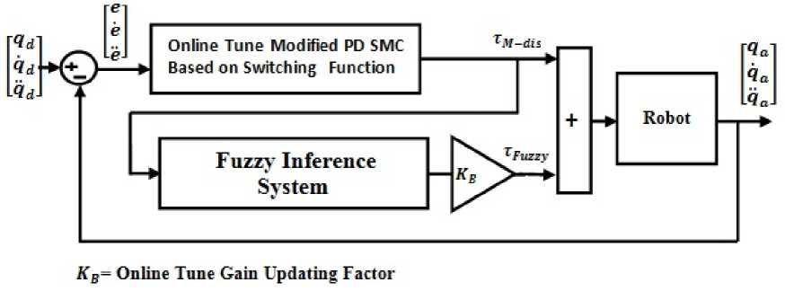
Fig. 4. Parallel optimization of on-line tuning modified PD partly nonlinear switching SMC based on fuzzy inference engine
-
IV. R esults A nd D iscussion
In this section, we use a benchmark model, robot manipulator, to evaluate our control algorithms. We compare the following managements: pure Modified PD partly linear switching sliding mode controller and proposed method with application to continuum robot. The simulation was implemented in MATLAB/ SIMULINK environment.
System’s coefficients optimization based on GDO:
This part focuses on the optimization result based on GDO. Most of iteration is used to reach the best modified PD coefficient and gain updating factor. Fig. 5 shows the optimization part.
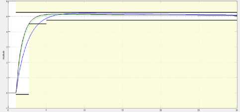
Fig. 5. System optimization based on GDO
Close loop response of continuum robot manipulator trajectory planning: Fig 6 illustrates the tracking performance in two types of controllers.
Based on Fig 6; conventional controller has overshoot and steady state error in all links, because robot is a highly nonlinear system and control of this system by conventional nonlinear method is very difficult.
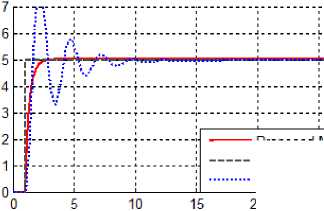
Fig. 6. Modified partly Nonlinear PD switching SMC and Proposed method
-----Proposed Method reference signal PD switching SMC
Close loop response of trajectory planning in presence of disturbance: Fig 7 demonstrates the power disturbance elimination in two types of controller in presence of disturbance for continuum robot manipulator. The disturbance rejection is used to test the robustness comparisons of these two methodologies. Based on Fig 7; by comparison with the conventional controller and proposed methodology, it can seen that proposed method is more stable and robust and this method is work based in chattering free methodology.
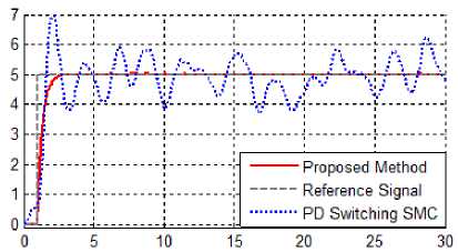
Fig. 7. Modified partly Nonlinear PD switching SMC and Proposed method with disturbance
-
V. C onclusion
Refer to this research 7 rules Mamdani’s fuzzy inference system is design and applied to modify PD partly nonlinear switching SMC to design high quality controller. Based on the dynamic formulation, continuum robot arm is highly nonlinear and uncertain dynamic parameters and control of this system based on classical methodology is very complicated. The main contributions of this paper are compensating the nonlinear model base controller by fuzzy inference system compensator, design band limited derivative modified PD switching SMC and online tuning all controllers’ coefficient based on linear methodology. The stability analysis of this methodology is test via Lyapunov methodology. The benefits of the proposed method; the chattering effects of parallel fuzzy inference compensator plus switching partly nonlinear sliding mode controller and modified PD, the slow convergence of the fuzzy and the chattering problem of pure sliding mode method are avoided effectively.
A cknowledgment
The authors would like to thank the anonymous reviewers for their careful reading of this paper and for their helpful comments. This work was supported by the SSP Research and Development Corporation Program of Iran under grant no. 2012-Persian Gulf-3C.
References Design Intelligent Robust Partly Linear Term SMC for Robot Manipulator Systems
- T. R. Kurfess, Robotics And Automation Handbook: Crc, 2005.
- J. J. E. Slotine And W. Li, Applied Nonlinear Control Vol. 461: Prentice Hall Englewood Cliffs, Nj, 1991.
- L. Cheng, Et Al., "Multi-Agent Based Adaptive Consensus Control For Multiple Manipulators With Kinematic Uncertainties," 2008, Pp. 189-194.
- J. J. D'azzo, Et Al., Linear Control System Analysis And Design With Matlab: Crc, 2003.
- B. Siciliano And O. Khatib, Springer Handbook Of Robotics: Springer-Verlag New York Inc, 2008.
- I. Boiko, Et Al., "Analysis Of Chattering In Systems With Second-Order Sliding Modes," Ieee Transactions On Automatic Control, Vol. 52, Pp. 2085-2102, 2007.
- J. Wang, Et Al., "Indirect Adaptive Fuzzy Sliding Mode Control: Part I: Fuzzy Switching," Fuzzy Sets And Systems, Vol. 122, Pp. 21-30, 2001.
- F. Piltan, Et Al., "Artificial Control Of Nonlinear Second Order Systems Based On Afgsmc," Australian Journal Of Basic And Applied Sciences, 5(6), Pp. 509-522, 2011.
- V. Utkin, "Variable Structure Systems With Sliding Modes," Automatic Control, Ieee Transactions On, Vol. 22, Pp. 212-222, 2002.
- R. A. Decarlo, Et Al., "Variable Structure Control Of Nonlinear Multivariable Systems: A Tutorial," Proceedings Of The Ieee, Vol. 76, Pp. 212-232, 2002.
- K. D. Young, Et Al., "A Control Engineer's Guide To Sliding Mode Control," 2002, Pp. 1-14.
- Samira Soltani & Farzin Piltan, “Design Artificial Nonlinear Controller Based On Computed Torque Like Controller With Tunable Gain”, World Applied Science Journal (Wasj), 14 (9): 1306-1312, 2011.
- Farzin Piltan, Mohammadali Dialame, Abbas Zare & Ali Badri,“Design Novel Lookup Table Changed Auto Tuning Fsmc:Applied To Robot Manipulator”, International Journal Of Engineering, 6 (1):25-41, 2012
- Farzin Piltan, Mohammad Keshavarz, Ali Badri & Arash Zargari,“Design Novel Nonlinear Controller Applied To Robotmanipulator: Design New Feedback Linearization Fuzzy Controller With Minimum Rule Base Tuning Method”, International Journal Of Robotics And Automation,3 (1):1-12, 2012
- Farzin Piltan, Iman Nazari, Sobhan Siamak, Payman Ferdosali,“Methodology Of Fpga-Based Mathematical Error-Based Tuning Sliding Mode Controller”, International Journal Of Control And Automation, 5(1), 89-118, 2012
- Farzin Piltan, Bamdad Boroomand, Arman Jahed & Hossein Rezaie, “Methodology Of Mathematical Error-Based Tuning Sliding Mode Controller”, International Journal Of Engineering, 6 (2):96-117, 2012
- Farzin Piltan, Sara Emamzadeh, Zahra Hivand, Fatemeh Shahriyari & Mina Mirazaei, ”Puma-560 Robot Manipulator Position Sliding Mode Control Methods Using Matlab/Simulink And Their Integration Into Graduate/Undergraduate Nonlinear Control, Robotics And Matlab Courses”, International Journal Of Robotics And Automation, 3(3):106-150, 2012
- Farzin Piltan, Ali Hosainpour, Ebrahim Mazlomian, Mohammad Shamsodini, Mohammad H. Yarmahmoudi, ”Online Tuning Chattering Free Sliding Mode Fuzzy Control Design: Lyapunov Approach”, International Journal Of Robotics And Automation, 3(3):77-105, 2012
- Farzin Piltan, Mina Mirzaei, Forouzan Shahriari, Iman Nazari, Sara Emamzadeh, “Design Baseline Computed Torque Controller”, International Journal Of Engineering, 6(3): 129-141, 2012
- Farzin Piltan, Mohammad H. Yarmahmoudi, Mohammad Shamsodini, Ebrahim Mazlomian, Ali Hosainpour, ”Puma-560 Robot Manipulator Position Computed Torque Control Methods Using Matlab/Simulink And Their Integration Into Graduate Nonlinear Control And Matlab Courses”, International Journal Of Robotics And Automation, 3(3): 167-191, 2012
- Farzin Piltan, Hossein Rezaie, Bamdad Boroomand, Arman Jahed, “Design Robust Backstepping On-Line Tuning Feedback Linearization Control Applied To Ic Engine”, International Journal Of Advance Science And Technology, 11:40-22, 2012
- Farzin Piltan, Mohammad R. Rashidian, Mohammad Shamsodini And Sadeq Allahdadi, Effect Of Rule Base On The Fuzzy-Based Tuning Fuzzy Sliding Mode Controller: Applied To 2nd Order Nonlinear System”, International Journal Of Advanced Science And Technology, 46:39-70, 2012
- Farzin Piltan, Arman Jahed, Hossein Rezaie And Bamdad Boroomand, ”Methodology Of Robust Linear On-Line High Speed Tuning For Stable Sliding Mode Controller: Applied To Nonlinear System”, International Journal Of Control And Automation, 5(3): 217-236, 2012
- Farzin Piltan, Bamdad Boroomand, Arman Jahed And Hossein Rezaie, ”Performance-Based Adaptive Gradient Descent Optimal Coefficient Fuzzy Sliding Mode Methodology”, International Journal Of Intelligent Systems And Applications, , Vol.4, No.11, Pp.40-52, 2012.
- Farzin Piltan, Mehdi Akbari, Mojdeh Piran , Mansour Bazregar, ”Design Model Free Switching Gain Scheduling Baseline Controller With Application To Automotive Engine”, International Journal Of Information Technology And Computer Science, Vol.5, No.1, Pp.65-73, 2013.Doi: 10.5815/Ijitcs.2013.01.07.
- Farzin Piltan, Mojdeh Piran , Mansour Bazregar, Mehdi Akbari, “Design High Impact Fuzzy Baseline Variable Structure Methodology To Artificial Adjust Fuel Ratio”, International Journal Of Intelligent Systems And Applications, Vol.5, No.2, Pp.59-70, 2013.Doi: 10.5815/Ijisa.2013.02.0.
- Farzin Piltan, M. Bazregar, M. Kamgari, M. Akbari And M. Piran, “Adjust The Fuel Ratio By High Impact Chattering Free Sliding Methodology With Application To Automotive Engine”, International Journal Of Hybrid Information Technology, 6(1), 2013.
- Farzin Piltan, S. Zare , F. Shahryarzadeh, M. Mansoorzadeh, M. Kamgari, “Supervised Optimization Of Fuel Ratio In Ic Engine Based On Design Baseline Computed Fuel Methodology”, International Journal Of Information Technology And Computer Science , Vol.5, No.4, Pp.76-84, 2013.Doi: 10.5815/Ijitcs.2013.04.09.
- Farzin Piltan, M. Mansoorzadeh, S. Zare, F.Shahryarzadeh, M. Akbari, “Artificial Tune Of Fuel Ratio: Design A Novel Siso Fuzzy Backstepping Adaptive Variable Structure Control”, International Journal Of Electrical And Computer Engineering, 3(2), 2013.
- M. Bazregar, Farzin Piltan, A. Nabaee And M.M. Ebrahimi, “Parallel Soft Computing Control Optimization Algorithm For Uncertainty Dynamic Systems”, International Journal Of Advanced Science And Technology, 51, 2013.
- Farzin Piltan, M.H. Yarmahmoudi, M. Mirzaei, S. Emamzadeh, Z. Hivand, “Design Novel Fuzzy Robust Feedback Linearization Control With Application To Robot Manipulator”, International Journal Of Intelligent Systems And Applications , Vol.5, No.5, Pp.1-10, 2013.Doi: 10.5815/Ijisa.2013.05.01.
- Sh. Tayebi Haghighi, S. Soltani, Farzin Piltan, M. Kamgari, S. Zare, “Evaluation Performance Of Ic Engine: Linear Tunable Gain Computed Torque Controller Vs. Sliding Mode Controller”, International Journal Of Intelligent Systems And Applications, Vol.5, No.6, Pp.78-88, 2013.Doi: 10.5815/Ijisa.2013.06.10.
- Amin Jalali, Farzin Piltan, M. Keshtgar, M. Jalali, “Colonial Competitive Optimization Sliding Mode Controller With Application To Robot Manipulator”, International Journal Of Intelligent Systems And Applications, Vol.5, No.7, Pp.50-56, 2013. Doi: 10.5815/Ijisa.2013.07.07.
- Salehi, Farzin Piltan, M. Mousavi, A. Khajeh, M. R. Rashidian, “Intelligent Robust Feed-Forward Fuzzy Feedback Linearization Estimation Of Pid Control With Application To Continuum Robot”, International Journal Of Information Engineering And Electronic Business, Vol.5, No.1, Pp.1-16, 2013. Doi: 10.5815/Ijieeb.2013.01.01.
- Farzin Piltan, M.J. Rafaati, F. Khazaeni, A. Hosainpour, S. Soltani, “A Design High Impact Lyapunov Fuzzy Pd-Plus-Gravity Controller With Application To Rigid Manipulator”, International Journal Of Information Engineering And Electronic Business, Vol.5, No.1, Pp.17-25, 2013. Doi: 10.5815/Ijieeb.2013.01.02.
- Amin Jalali, Farzin Piltan, A. Gavahian, M. Jalali, M. Adibi, “Model-Free Adaptive Fuzzy Sliding Mode Controller Optimized By Particle Swarm For Robot Manipulator”, International Journal Of Information Engineering And Electronic Business, Vol.5, No.1, Pp.68-78, 2013. Doi: 10.5815/Ijieeb.2013.01.08.
- Farzin Piltan, F. Shahryarzadeh, M. Mansoorzadeh, M. Kamgari, S. Zare, “Robust Fuzzy Pd Method With Parallel Computed Fuel Ratio Estimation Applied To Automotive Engine“, International Journal Of Intelligent Systems And Applications, Vol.5, No.8, Pp.83-92, 2013. Doi: 10.5815/Ijisa.2013.08.10.
- Farzin Piltan, A. Nabaee, M.M. Ebrahimi, M. Bazregar, “Design Robust Fuzzy Sliding Mode Control Technique For Robot Manipulator Systems With Modeling Uncertainties”, International Journal Of Information Technology And Computer Science, Vol.5, No.8, Pp.123-135, 2013. Doi: 10.5815/Ijitcs.2013.08.12.
- Farzin Piltan, M. Mansoorzadeh, M. Akbari, S. Zare, F. Shahryarzadeh “Management Of Environmental Pollution By Intelligent Control Of Fuel In An Internal Combustion Engine“ Global Journal Of Biodiversity Science And Management, 3(1), 2013.
- M. M. Ebrahimit Farzin Piltan, M. Bazregar And A.R. Nabaee, “Intelligent Robust Fuzzy-Parallel Optimization Control Of A Continuum Robot Manipulator”, International Journal Of Control And Automation, 6(3), 2013.
- O.R. Sadrnia, Farzin Piltan, M. Jafari, M. Eram And M. Shamsodini, “Design Pid Estimator Fuzzy Plus Backstepping To Control Of Uncertain Continuum Robot”, International Journal Of Hybrid Information Technology, 6(4), 2013.
- Aminjalali, Farzin Piltan, H. Hashemzadeh, A. Hasiri, M.R Hashemzadeh, “Design Novel Soft Computing Backstepping Controller With Application To Nonlinear Dynamic Uncertain System”, International Journal Of Intelligent Systems And Applications, Vol.5, No.10, Pp.93-105, 2013. Doi: 10.5815/Ijisa.2013.10.12.
- M. Moosavi, M. Eram, A. Khajeh, O. Mahmoudi And Farzin Piltan, “Design New Artificial Intelligence Base Modified Pid Hybrid Controller For Highly Nonlinear System”, International Journal Of Advanced Science And Technology, 57, 2013.
- S. Zahmatkesh, Farzin Piltan, K. Heidari, M. Shamsodini, S. Heidari, “Artificial Error Tuning Based On Design A Novel Siso Fuzzy Backstepping Adaptive Variable Structure Control” International Journal Of Intelligent Systems And Applications, Vol.5, No.11, Pp.34-46, 2013. Doi: 10.5815/Ijisa.2013.11.04.
- S. Heidari, Farzin Piltan, M. Shamsodini, K. Heidari And S. Zahmatkesh, “Design New Nonlinear Controller With Parallel Fuzzy Inference System Compensator To Control Of Continuum Robot Manipulator”,International Journal Of Control And Automation, 6(4), 2013.
- Farzinpiltan, M. Kamgari, S. Zare, F. Shahryarzadeh, M. Mansoorzadeh, “Design Novel Model Reference Artificial Intelligence Based Methodology To Optimized Fuel Ratio In Ic Engine”, International Journal Of Information Engineering And Electronic Business, Vol.5, No.2, Pp.44-51, 2013. Doi: 10.5815/Ijieeb.2013.02.07.
- Farzin Piltan, Mehdi Eram, Mohammad Taghavi, Omid Reza Sadrnia, Mahdi Jafari,"Nonlinear Fuzzy Model-Base Technique To Compensate Highly Nonlinear Continuum Robot Manipulator", Ijisa, Vol.5, No.12, Pp.135-148, 2013. Doi: 10.5815/Ijisa.2013.12.12
- Amin Jalali, Farzin Piltan, Mohammadreza Hashemzadeh, Fatemeh Bibakvaravi, Hossein Hashemzadeh,"Design Parallel Linear Pd Compensation By Fuzzy Sliding Compensator For Continuum Robot", Ijitcs, Vol.5, No.12, Pp.97-112, 2013. Doi: 10.5815/Ijitcs.2013.12.12
- Farzin Piltan, A. Hosainpour, S. Emamzadeh, I. Nazari, M. Mirzaie, “Design Sliding Mode Controller Of With Parallel Fuzzy Inference System Compensator To Control Of Robot Manipulator”, International Journal Of Robotics And Automation, Vol. 2, No. 4, December 2013, Pp. 149~162.
- Farzin Piltan, Mahdi Jafari, Mehdi Eram, Omid Mahmoudi, Omid Reza Sadrnia, "Design Artificial Intelligence-Based Switching Pd Plus Gravity For Highly Nonlinear Second Order System", International Journal Of Engineering And Manufacturing, Vol.3, No.1, Pp.38-57, 2013.Doi: 10.5815/Ijem.2013.01.04
- Farzin Piltan, Sara Emamzadeh, Sara Heidari, Samaneh Zahmatkesh, Kamran Heidari, "Design Artificial Intelligent Parallel Feedback Linearization Of Pid Control With Application To Continuum Robot", International Journal Of Engineering And Manufacturing, Vol.3, No.2, Pp.51-72, 2013.Doi: 10.5815/Ijem.2013.02.04
- Mohammad Mahdi Ebrahimi, Farzin Piltan, Mansour Bazregar, Alireza Nabaee,"Artificial Chattering Free On-Line Modified Sliding Mode Algorithm: Applied In Continuum Robot Manipulator", International Journal Of Information Engineering And Electronic Business, Vol.5, No.5, Pp.57-69, 2013. Doi: 10.5815/Ijieeb.2013.05.08
- Arman Jahed, Farzin Piltan, Hossein Rezaie, Bamdad Boroomand, "Design Computed Torque Controller With Parallel Fuzzy Inference System Compensator To Control Of Robot Manipulator", International Journal Of Information Engineering And Electronic Business, Vol.5, No.3, Pp.66-77, 2013. Doi: 10.5815/Ijieeb.2013.03.08
- Mohammad Shamsodini, Farzin Piltan, Mahdi Jafari, Omid Reza Sadrnia, Omid Mahmoudi,"Design Modified Fuzzy Hybrid Technique: Tuning By Gdo", Ijmecs, Vol.5, No.8, Pp.58-72, 2013.Doi: 10.5815/Ijmecs.2013.08.07
- Mahdi Mirshekaran, Farzin Piltan,Zahra Esmaeili, Tannaz Khajeaian, Meysam Kazeminasab,"Design Sliding Mode Modified Fuzzy Linear Controller With Application To Flexible Robot Manipulator", Ijmecs, Vol.5, No.10, Pp.53-63, 2013.Doi: 10.5815/Ijmecs.2013.10.07
- Meysam Kazeminasab, Farzin Piltan, Zahra Esmaeili, Mahdi Mirshekaran, Alireza Salehi ,"Design Parallel Fuzzy Partly Inverse Dynamic Method Plus Gravity Control For Highly Nonlinear Continuum Robot", Ijisa, Vol.6, No.1, Pp.112-123, 2014. Doi: 10.5815/Ijisa.2014.01.12.
- Mansour Bazregar, Farzin Piltan, Mehdi Akbari, Mojdeh Piran,"Management Of Automotive Engine Based On Stable Fuzzy Technique With Parallel Sliding Mode Optimization", Ijitcs, Vol.6, No.1, Pp.101-107, 2014. Doi: 10.5815/Ijitcs.2014.01.12.
- Ali Shahcheraghi, Farzin Piltan, Masoud Mokhtar, Omid Avatefipour, Alireza Khalilian,"Design A Novel Siso Off-Line Tuning Of Modified Pid Fuzzy Sliding Mode Controller", Ijitcs, Vol.6, No.2, Pp.72-83, 2014. Doi: 10.5815/Ijitcs.2014.02.10
- Kamran Heidari, Farzin Piltan, Samaneh Zahmatkesh, Sara Heidari, Mahdi Jafari,"Design High Efficiency Intelligent Robust Backstepping Controller ", Ijieeb, Vol.5, No.6, Pp.22-32, 2013. Doi: 10.5815/Ijieeb.2013.06.03.
