Design of Adder Using Quantum Cellular Automata

Author: K.Sundara Rao, Mrudula Singamsetti, Vuyyuru Tejaswi
Journal: International Journal of Wireless and Microwave Technologies @ijwmt
Article in issue: 6 Vol.9, 2019.
Free access
QCA is the trending technologies for designing less hardware and low power consumed circuits measured in Nano-scale. These QCA cells are accustomed to construct combinational and sequential circuits. In this paper we presented a design for developing a basic arithmetic unit called full adder using Quantum cellular automata. The new submitted FA consists fewer amounts of quantum cells and delay also minimizes, when compared with the existing architecture.
Full adder (FA), Majority Gate (MG), QCA cell
Short address: https://sciup.org/15017163
IDR: 15017163 | DOI: 10.5815/ijwmt.2019.06.02
Text of the scientific article Design of Adder Using Quantum Cellular Automata
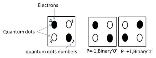
Fig.1. Basic Quantum Cellular Automata Structure
The 2 quantum dots and 2 electrons arrangement of a basic QCA structure is represented in the fig1.The expression of the polarization(P) of the quantum cell is shown in eq.1 [8]. P=-1 is represented as binary logical value’0’ and P=+1 is represented as binary logical value’1’ [16, 17], as shown in the fig.1.
р_ (P1 + P 3) - ( P 2 + P 4) = P 1 + P 2 + P 3 + P 4
Here ƿ1, ƿ2, ƿ3, ƿ4 designates the electrons that are located in the QCA basic structure. All the digital circuit designs are formulated utilizing QCA
QCA circuits are formulated utilizing majority gate which comprise of 5 QCA cells, out of which 3 are inputs,1 output and 1 processing cell shown in the fig.2.
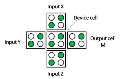
Fig.2. Majority Gate of 5 cells QCA
The logical expression of an MG is given in the eq.2.
f (a, b, c) = a. b + b. c + c .a
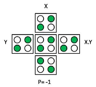
Designing digital circuits can be done by utilizing majority gates. From eq.2 one of the input is zero i.e assume c=’0’, then the majority gate works as a logical AND gate shown in fig.3.
f (a, b ,0) = a .b
Fig.3 QCA design for an AND Gate
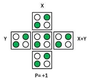
From eq.2 if c=’1’, then the MG works as a logical OR gate shown in fig.4
f (a, b ,1) = a + b
Fig.4 QCA design for an OR Gate
The QCA design for an inverter which is shown in fig.5
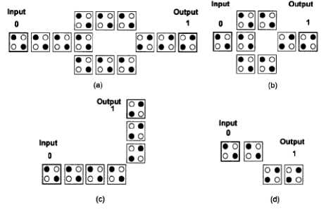
Fig.5 QCA design for an inverter
-
2. Literature Survey for the adder Design using QCA
A full adder is a design which adds 3 binary inputs and obtain 2 outputs Sum and Carry. The formulae for sum and carry using majority gates is given in eq.5 and eq.6. Finally, full adder structure requires five majority gates and three basic inverters [9] which is shown in fig.6.
Carry = f (a, b, c)
Sum = f ( f ( a ', b , c ), f ( a , b ', c ), f ( a , b , c ')) (6)
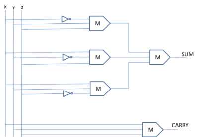
Fig.6 Basic Full adder using Majority gates
K. Navi [10] has proposed different logical expression which is given in the eq.7 ,eq.8 and its logical diagram is shown in fig.7.
Carry = f (a, b, c) (7)
Sum = f ( carry ', carry ', a , b , c ) (8)
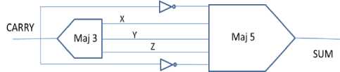
Fig.7. [10] Full adder QCA design
From [10] adders is developed by utilizing 3 input XOR gate [18] and five input majority gate. The 3 input XOR based on QCA is shown in fig.8 comprising 14 cells and assign one of the input is zero which behaves as an XOR gate.
' 1 XOR ®® • •
Fig.8. [18] 3-input XOR gate QCA design
-
3. Proposed design for Full adder using QCA
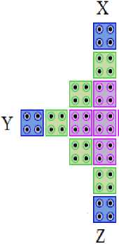
The structural design of the proposed design which comprising of 3 input majority gate and an XOR gate is shown in fig.9.The proposed design has 23 standard cell structure by using 2 clocks is shown in fig.10.Blue color represents full adder inputs, yellow color designated outputs and the remaining colors related to setup, hold, relax and release phases
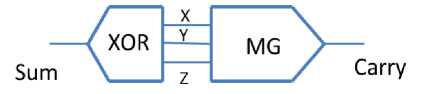
Fig.9 Proposed Full adder using 3 input XOR gate and majority gate

Fig.10. Proposed Full adder design using QCA
-
4. Simulated Results for the proposed adder
-
5. Conclusions
The possible output and input combinations are shown in fig.11.
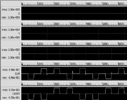
Fig.11. Simulated results of the waveform of proposed FA.
Table I shows the comparative analysis of full adder design using QCA. From Ref [8] the full adder has been constructed using 38 standard cell structure in which delay is more [11]. The proposed design requires the 23 standard QCA cell structure has better performance in terms of area and delay.
Table1. Comparative Analysis of QCA based Full adder design
|
Circuit |
No.of QCA cells |
Area in Nano square meters |
No.of Clock Phases |
|
In Ref. [9] |
192 |
190244 |
4 |
|
In Ref. [12] |
145 |
179901 |
4 |
|
In Ref. [13] |
107 |
115781 |
4 |
|
In Ref. [14] |
61 |
40512 |
3 |
|
In Ref. [15] |
51 |
37054 |
3 |
|
In Ref. [8] |
38 |
30568 |
3 |
|
In Ref. [11] |
31 |
23598 |
2 |
|
New Structure |
23 |
16284 |
2 |
The new structure for QCA based full adder which occupies less area in terms of QCA cell structures, number of clock phases, Area in Nano square meters compared to the other full adder architectures mentioned in the literature. The limitation for the proposed design is unable to reduce the number of clock because data transfer will not takes place.
References Design of Adder Using Quantum Cellular Automata
- Lent.C, Tougaw.P, "A device architecture for computing with quantum dots”, Proceedings of the IEEE, vol. 85, pp. 541-557, 1997.
- Farazkish.R, Azghadi.M, Haghparast.M and Navi.K,"New Method for Decreasing the Number of Quantum-dot Cells in QCA Circuits," World Applied Sciences Journal, vol. 6, pp. 793-802, 2008.
- Oya.T, Asai.T, Fukui.T, and Amemiya.Y, "A Majority-Logic Device Using an Irreversible Single-Electron Box," IEEE Transactions on Nanotechnology, vol. 2, 2003.
- Navi.K, Farazkish.R, Sayedsalehi.S, and Azghadi.M.R, "A New Quantum-dot Cellular Automata Full-adder," Microelectronics Journal, vol. 41, p. 820826, 2010.
- Dutta.P ,Mukhopadhyay.D, "New Architecture for Flip Flops using Quantum-dot Cellular Automata," Proceedings of the 48th Annual Convention of Computer Society of India Vol II Advances in Intelligent Systems and Computing, Springer-Verlag, vol. 249, pp. 707-714, 2013.
- Mukhopadhyay.D,Dutta.P,Dinda.S, Designing and Implementation of Quantum Cellular automata 2:1 Multiplexer Circuit," International Journal of Computer Applications, vol. 25, no. 1, pp. 21- 24, 2011.
- Mukhopadhyay.D,Dutta.P, " Quantum Cellular Automata Based Novel Unit 2: I Multiplexer," International Journal of Computer Applications, vol. 3, pp. 22-25, 2012.
- Mohammadi.M, S. Gorgin, M. Mohammadi, “An efficient design of full adder in quantum technology”, Microelectronics Journal, No.50, pp. 35-43, 2016.
- Douglas.Tougaw.P, Lent.C.S, "Logical devices implemented using quantum cell Mar automata" Department of Electrical Engineering, Universi~ of Notre Dame, Notre Dame, Indiana 46556 (Received 28 July 1993; accepted for publication 26 October 1993)
- Navi.K, Sayedsalehi.S, Farazkish.R, Azghadi.M.R,“A new quantum dot cellular automata full adder”, Microelectronics Journal, no. 41, pp. 820-826, 2010.
- NuriddinSafoev and Jun-CheolJeon “Full Adder Based on Quantum-dot Cellular Automata” 2017 Manila International Conference on “Trends in Engineering and Technology” (MTET-17) Jan. 23-24, 2017 Manila (Philippines).
- Devi.T.R, “Implementation of adder by using QCA technology”, 1993
- Peer Zahoor Ahmad, Dr. Rafiq Ahmad Khan , Firdous Ahmad,B. Syed Muzaffar Ahmad, ,“Implementation of Quantum dot Cellular Automata based Novel Full Adder and Full Subtractor“ International Journal of Science and Research (IJSR)Volume 3 Issue 8, August 2014.
- Navi.K, S. Saedsalehi,Farazkish.R, Azghadi.M.R, “Five-input majority gate, a new device for quantum dot cellular automata”, J. Comput.Theor.Nanosci, vol. 7, pp. 1546-1553, 2010.
- Hashemi.S, Tehrani.M, Navi.K, “An efficient quantum-dot cellular automata full-adder”, Sci. Res. Esseys, vol. 7, no. 2, pp. 177-189, 2012.
- Snider.O, Amlani.I, Bernstein, Lent.C.S, Merz.J.L, Porod.W, “A functional cell for quantum dot cellular automata, Solid-State Electron ”, vol. 42, pp. 1355-1359, 1998.
- Jeon.J.C, “Low hardware complexity QCA decoding architecture using inverter chain”, International Journal of Control and Automation, vol. 9, no. 4, pp. 347-358, 2016.
- Ahmad.F, Bhat.G.M, Khademolhosseini.H, Azimi.S, Angizi.S,Navi.K, “Towards single layer quantum dot cellular automata adders based on explicit interaction of cells”, Journal of Computer Science, vol. 16, pp.8-15, 2016.
