Design of an IoT-Enabled Solar Tracking System For Smart Farms
Author: JD Motha, MWP Maduranga, NT Jayatilaka
Journal: International Journal of Wireless and Microwave Technologies @ijwmt
Article in issue: 6 Vol.12, 2022.
Free access
This paper presents a novel IoT system to eliminate the need for human intervention for solar panel maintenance purposes in smart farms. For the convenience of the consumer, a wireless sensing system could be implemented to automate these functions. This would eliminate the cost of any additional labor charges for panel maintenance as the system implemented would automatically calculate the position as per the current time of the day and adjust the panel's position accordingly to harvest the most amount of sun rays into the PV panel. Unlike the conventional tracking method where the panel is rotated hourly, we propose a fixed set of Sun Altitude and Azimuth angle ranges that are hardcoded to each panel position so that throughout the year whenever these angles fall out of range it jumps to the next position. The system results in a straightforward method by retrieving the current date/time from the RTC module and calculating the respective Sun Altitude and Azimuth angle to determine the position to adjust the position of the panel accordingly, thus producing effective power outputs and strong sun tracking results.
IoT, Smart Farming, PV systems, Robotics
Short address: https://sciup.org/15019192
IDR: 15019192 | DOI: 10.5815/ijwmt.2022.06.01
Text of the scientific article Design of an IoT-Enabled Solar Tracking System For Smart Farms
All agriculture and home markets have both reported that energy demands have been increasing exponentially in recent years. There is no alternative but to employ renewable resources to create useable energy because non-renewable resources are quickly running out. Solar energy is one of these resources and is easily obtainable via Solar Panels. This project improves the effectiveness of the solar energy harvesting method. As the orientation of the sun varies throughout the day, it is required to position the panel accordingly to get the most amount of sunlight. Else the system would not prove efficient. With the aid of automated wireless systems save labor, time, and money while also improving the precision of the work done. The availability, performance, and dependability of the services offered are all improved as a result. One of the most promising areas nowadays is the utilization of such installations in solar systems. Wireless monitoring is a key component of monitoring a photovoltaic system's stability and performance and is planned to achieve using SIM900A GSM module with ESP8266 microcontroller. The photovoltaic monitoring system may be utilized in solar-powered automobiles, houses, street lighting, and other application areas as well.
A tool that tracks the sun's path across the sky is called a solar tracker. Solar panels that are connected to solar trackers can track the sun's movement and generate more green energy for our usage. Solar tracking systems come in three different varieties. Manual solar trackers need to have the panels physically adjusted to follow the sun at various points of the day. This isn't always feasible since you need someone to continuously check the sun's location and move the solar panel system. The Passive Solar Trackers contain a low boiling-point liquid that will vaporize when exposed to sunlight. The tilt mechanism becomes unbalanced as the liquid evaporates. Due to this imbalance, the panels begin to tilt toward the rays of the sun. Moreover, active solar trackers, active trackers use motors or hydraulic cylinders. The PV panels will be moved by the motors in active trackers to face the sun. Although this is more practical than manual trackers, the motors' moving parts might malfunction. Throughout the system's lifespan, this can result in greater maintenance expenses [1].
The existing systems are of two types which are single axis and dual axis tracking systems. However, the effectiveness of single-axis trackers decreases as they approach the North. It is thus because there is a greater variation in the sun angle between summer and winter. When it's sunny outside, single-axis trackers produce less energy than dual-axis trackers do. Dual axis trackers assist capture the most solar energy by tracking the sun's motion both vertically and horizontally. These trackers may be pricey, however. These trackers are less reliable and have a shorter lifespan. In this paper considering that single axis trackers are more reliable and is operable with a simple mechanism at a low cost I hope to achieve sufficient results solar energy harvesting via the tracking method implemented compared to the fixed standalone method of the panel.
2. Related Work
Several works are available in the literature on designing IoT-based solar tracking systems.
Kyi and Taparugssanagorn found out that when it comes to low power consumption, low cost, quick data transmission time, proximity, and low data transfer rate, ZigBee was the best option among the various wireless data transmission technologies [3].
The author has observed that a dual dual-axis solar tracker with a tilt angle in auto mode and elevation in manual mode generates more power than a fixed rack. Furthermore, an Arduino-controlled H-bridge motor drive and a Direct Current (DC) motor rotate the solar PV panel hourly to change the solar PhotoVoltaic (PV) panel following the sun. The solar PV panel is turned on when the clock strikes 0900 hours, the Arduino turns off the motor when the voltage across the potentiometer hits 1.25 V. Similarly, it occurs every hour until 1600 hours The software resets the motor to 0800 hours when the clock strikes 1600 hours. In contrast, the azimuth and elevation angles remain fixed at midday [3].
All the sensors are connected to an Arduino Uno (microcontroller), which is connected to a ZigBee end device through an XBee ZNet 2.5 module. Signals such as PV voltage, PV current, battery voltage, load current, and converter transistor temperature are wirelessly sent through the XBee Znet 2.5. The PC is connected to the second XBee Znet 2.5 utilized as a ZigBee coordinator. A Graphical User Interface (GUI) designed with Processing software is used to control the system. On the computer monitor, the voltages, currents, and temperature are shown [3].
Kuttubay et al contributed to designing a more efficient and cost-effective method in terms of eliminating human intervention. Wireless automated systems save labor, time, and money while also improving the precision of the work done. The availability, performance, and dependability of the services supplied are all improved as a result. The use of photovoltaic systems is in high demand and can be used in solar-powered cars, solar-powered buses, solar-powered trains, etc. In terms of designing the project to be cost-effective and low power, the authors had decided to use LoRa E32 modules as wireless receiving and transmitting devices and the monitoring systems are based on the LabView software [4].
An ammeter and voltmeter are mounted at the output of the solar panel, as well as the output of the battery charge controller, to measure the output electrical properties of the devices and transfer data to the microcontroller (8-bit Atmega328PU). After processing all the incoming data, the microcontroller transfers the data via the LoRa E32 wireless module. A wireless module LoRa E32 is also included in the device's reception section. The microcontroller uses the installed sensors to collect data and communicates it to the dispatcher through the LoRa E32 wireless module. The microcontroller then enters sleep mode for a certain amount of time [4].
Lopez, Mantinan, and Molina intended to create a solar photovoltaic distributed generator (PV-DG). Due to the many advantages of using renewable energy in distributed generation systems, including the advocate support provided by ministries in many countries in the form of additional funding and campaigns for awareness, there has been an increased interest in connecting PV generation to the electricity grid. In [8] The author intends to create a solar photovoltaic distributed generator (PV-DG) for use in microgrids. The project uses Zigbee Protocol for wireless communication between the WSNs where four XBee PRO modules were used and linked the PV panels to a singlephase utility grid using a 1.2 kVA/1.2 kW/120 Vdc commercial inverter. The system is supervised by a DSP dsPIC 30F3013 microcontroller unit for data collection and could be processed on a host computer connected via the UART/USB bridge where the implementation could be viewed on the GUI of LabView software [5].
Waleed, Riaz, Muneer, Ahmad, Mughal , Zafar, and Shakoor studied that in regions where electricity is hard to come by, solar-powered water pumping systems are widely employed in crop or farm cultivation. The main benefit of this water pumping system is its simplicity and lower total cost due to the absence of fossil fuels. There are two types of PV-powered water pumping systems, but here battery coupled is used because it could still be operated day/night without a power failure [6].
A PV panel, solar charge controller, inverter, humidity sensors, and a SIM900 GSM module were used for communication. The humidity sensor is also attached to the GSM module, which allows the values to be transmitted to the central control unit and farmers. The entire system is powered by solar panels, which eliminates the need for the grid and saves energy [6].
Al-Naima and Hamad classified the system based on two parts. The client side is made up of hardware components, are placed such as voltage sensors, current sensors (ACS712), temperature sensors (DHT11), humidity sensors that read PV panel characteristics, and WSN modules that communicate the data to a cloud database. The other part is the server side where it allows users to log in and view the collected data using a visual user interface built with PHP and HTML. Sensor data is stored and retrieved using the ThingSpeak Cloud database. To communicate with the ThingSpeak servers, a NodeMCU microcontroller was used so it relies on a WiFi connection (for connectivity OTA) and can easily be connected as it has an ESP8266 WiFi chip built-in. A multiplexer (GD4051B) is also used to link and regulate the switching between all the sensors [7].
Murugesh et al, recommend that having a Wireless Solar Power Monitor would benefit in detecting faults in the PV panel, battery, or network node fixed at remote/hard-to-reach locations. Once again power consumption must be the top priority as a rechargeable solar power battery will power it so the microcontroller chosen for this process would be the MSP430 wireless development board which is a low-cost and ultra-low power microcontroller-based wireless solar power monitor that can be plugged easily into a PV system. This system also consisted of three pairs of voltage and current sensors to measure the voltages and currents at the terminals of the PV module, battery, and load. A GPRS-activated GSM module was used here as well along with the MCU to transmit all the gathered data using TCP or UDP protocols. The usage of this power monitor should help to extend the life of the PV system and reduce power outages in the PV-powered WSN nodes [8].
Arslan et al. offer a way to determine the sun's exact position Sun compared with results from the National Renewable Energy Laboratory (NREL) that may be beneficial for tracking the sun without sensors. The suggested approach combines several sun position-calculating equations. A charge-coupled device (CCD) camera image of the sun was employed to fix the system's tracking flaws because the method used in this study had low accuracy. A CCD camera was used to fine-tune the location once the tracker had been roughly oriented to the sun. The sun position algorithm determines where the sun is located inside a given coordinate system. Time and location are provided as inputs, and the method returns the sun's reference frame coordinates. The efficiency of the tracker is impacted by the algorithm's accuracy. An algorithm like the one described earlier has been put to the test against the sophisticated NREL method, and it turns out that it is a good substitute for the complex NREL approach. The NREL sun position algorithm was used to evaluate and validate the method's correctness. The mean difference in azimuth and elevation angle was determined to be 0.22 degrees and 0.4 degrees, respectively [9].
Akhlaghi et al. looked at how different tilt angles affected a solar panel's production. According to their research, altering a solar panel's tilt angle eight times a year allows it to gather the same amount of energy as when it is altered daily. It was claimed that employing 12 intervals throughout the year will provide the most solar energy. To improve the efficiency of solar panels, the authors estimated the ideal tilt angle for Saudi Arabia. The author has shown that monthly solar panel adjustment may provide 8% more electricity than yearly adjustment [10].
The study was done in the US, and the findings showed that solar panels generate 10- 25% more electricity with rising latitude for a certain tilt angle. According to the study, finding the best tilt angle for the whole year would result in a large loss of solar power since the ideal tilt angle changes greatly during the year [10].
In this work, the Bee Algorithm (BA) is used to calculate the ideal tilt angle for a designated period. The research is conducted throughout several US cities, including Bakersfield, Binghamton, Chicopee Falls, Concordia, Elmira, Erie, Santa Fe County, Seattle-Tacoma, and Wilkes-Barre.
It was seen, that for solar panels installed in Binghamton, New York, adjusting the optimal tilt angle twice a year only results in a 5.05 Kw/m2 increase in total power over a fixed tilt angle, whereas adjusting the tilt angle four times results in a 185.29 Kw/m2 increase in power over a fixed adjustment. The research demonstrates that, barring extreme weather, overall power generation often rises as we approach the equator. The findings demonstrate that 4 or 5 intervals are the ideal number of intervals in the US for manually adjusting the tilt angle, regardless of where a solar panel is located across the country. In this work, the Bee Algorithm (BA), which was developed in the Python environment, was used to calculate the ideal tilt angle for a given interval [10].
Some of the gaps which were observed in most of the related work were the wireless technologies used. As some used Zigbee, it was only proven to work within the limited Zigbee range. The same scenario applies for projects carried out using NodeMCU WiFi modules as well, but Zigbee slightly has the higher advantage. To get the better of these two wireless technologies, GSM seemed to be the viable option but the limitation with it is that GPRS signals may fluctuate at times and cause delays between messages. A few authors also noted that during rain/ cloudy weather conditions the PV power dropped causing the grid to get disconnected and produce an irregular power curve.
3. Approach 3.1 Altitude and Azimuth Angle
Firstly, to achieve accurate tracking of the sun we need to calculate the position of the sun at any given time which requires two specific angles that are Altitude and Azimuth angles respectively [11].
The Altitude Angle (β) (Vertical angle above the horizon) is the vertical angular distance between a celestial body (sun, moon) and the observer’s local horizon/ local plane.
sin (p) = cos(L)cos(8)cos(H) + sin(L)sin(8)(1)
The Azimuth Angle (γ) (Horizontal angle along the horizon) is the angle between a celestial body (sun, moon) and the North, measured clockwise around the observer’s horizons.
Azimuth = cos - 1 [(sin(8) cos(L) - cos(8)] sin(L) cos(H))/cos(P)](2)
For Local Solar Time (LST) < 12
Azimuth = Azi(3)
For Local Solar Time (LST) > 12
Azimuth = 360° — Azi(4)
But to calculate the β and γ we need to know about three more angles additionally which are the Solar Declination Angle, Latitude Angle, and Hour Angle. Solar Declination Angle (δ), is the angle between the light rays from the Sun and the Earth’s equator.
8 = 23.45 * sin (360 / (365 (n — 81)))(5)
Where n is the number of days from the beginning of the year. For example, Jan 1st, n=1 Dec 31st , n = 365
Latitude Angle (L), is the line joining any position on the surface of Earth to the center of Earth tilted above the equator.
Hour Angle (H), is the angle by which the Earth must rotate before the Sun will be over the local meridian.
Earth rotates 15 ° every hour.
H= 15 ° * hours before solar noon (6)
Solar noon is assumed as 1200 but maybe a little more or a little less.
Table 1. Calculation of hour angle from 0600 to 1800 assuming solar noon is at 1200 [12].
|
Time |
Hours before Solar Noon |
Hour Angle (H) |
|
0600 |
6 |
90 |
|
0700 |
5 |
75 |
|
0800 |
4 |
60 |
|
0900 |
3 |
45 |
|
1000 |
2 |
30 |
|
1100 |
1 |
15 |
|
1200 |
0 |
0 |
|
1300 |
1 |
-15 |
|
1400 |
2 |
-30 |
|
1500 |
3 |
-45 |
|
1600 |
4 |
-60 |
|
1700 |
5 |
-75 |
|
1800 |
6 |
-90 |
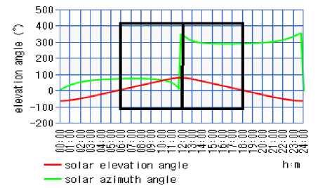
Fig. 1. Graph of Solar Elevation and Azimuth angles.
Fig.1 shows how the Sun’s position tracks throughout a particular day at a location in Sri Lanka obtained from Casio’s Keisan Online Solar Elevation Calculator, the black box indicates the period of tracking from 0600 to 1800 [13].
Table 2. Accuracy of the calculated Azimuth and Altitude values vs. the actual values on a particular day.
|
Time |
Actual Value |
Calculated Value |
Accuracy |
|||
|
Azimuth/° |
Altitude/° |
Azimuth/° |
Altitude/° |
Azimuth/% |
Altitude/% |
|
|
7AM |
77.01 |
12.61 |
77.58 |
16.13 |
99.26 |
72.08 |
|
9AM |
77.19 |
41.64 |
77.27 |
45.28 |
99.89 |
91.25 |
|
11AM |
66.99 |
70.24 |
63.5 |
73.69 |
94.79 |
95.08 |
|
1PM |
303.97 |
76.77 |
296.5 |
73.69 |
97.54 |
95.98 |
|
3PM |
283.51 |
48.83 |
282.73 |
45.25 |
99.72 |
92.67 |
|
5PM |
282.45 |
19.77 |
282.42 |
16.13 |
99.98 |
81.58 |
3.2 Internet of Things for Data Transmission
4. System Design
Today's cellular networks enable us to send and receive massive amounts of data quickly and reliably over long distances. The drawback of these cellular devices is still their high-power consumption and high price. To run IoT devices over carrier networks, either within an existing GSM Carrier wave in unused guard bands between LTE channels or independently, NB-IoT is a communication standard that is a part of the licensed LPWAN radio technology. It is built to function with limited devices, which are devices that have restrictions on things like processing power, network connectivity, and battery life. It can support a sizable number of endpoint devices over just 200MHz of the spectrum. Due to its design for low data rates where minor delays are acceptable, NB-IoT is effective in tackling this issue in IoT implementations that don't have a high requirement for bandwidth or low latency. (Ex: Fixed-location smart parking meters giving sporadic updates). The NB-IoT architecture does not require gateways and the sensors can directly communicate with primary servers [14].
In comparison to unlicensed LPWA networks like LoRa/Sigfox, it offers improved scalability, quality of service, and security because it employs a mobile wireless network and also provides extended coverage to GSM/GPRS systems [15]. Better penetration in the signals can be observed compared to the standard unlicensed bands such as LoRaWAN and Sigfox. It coexists with other older cellular technologies including GSM, GPRS, and LTE. Any old LTE network may accommodate the deployment and scheduling of NB-IoT-certified devices.
Furthermore, it has its downsides as well since compared to LTE cat-M1, it provides a lesser data rate (about 250Kbps download and 20Kbps upload). About 200 KHz makes up the bandwidth. NB-IoT is therefore best suited for use with stationary devices only. Additionally, it does not support VoLTE (Voice Over LTE) for speech transmission. Hence voice transmission is not supported and in contrast to LTE-M and Sigfox, roaming is not supported as well [15].
The proposed system design is illustrated in Fig.2. Where the connected RTC Module will begin running from the programmed Date/Time and update accordingly. These parameters of current Date and Time are needed to calculate the relevant Solar Azimuth and Elevation angles for the Sun’s position.
With the aid of the MPU6050 gyroscope module attached to the panel, it’s possible to set to which specific X, Y, or Z angle to rotate the panel as a 12V DC motor is involved for panel rotation due to the difficulty in stopping at certain angles unlike Servos and stepper motors. The 2-channel relay module will then be used to rotate the panel clockwise and anticlockwise appropriately.
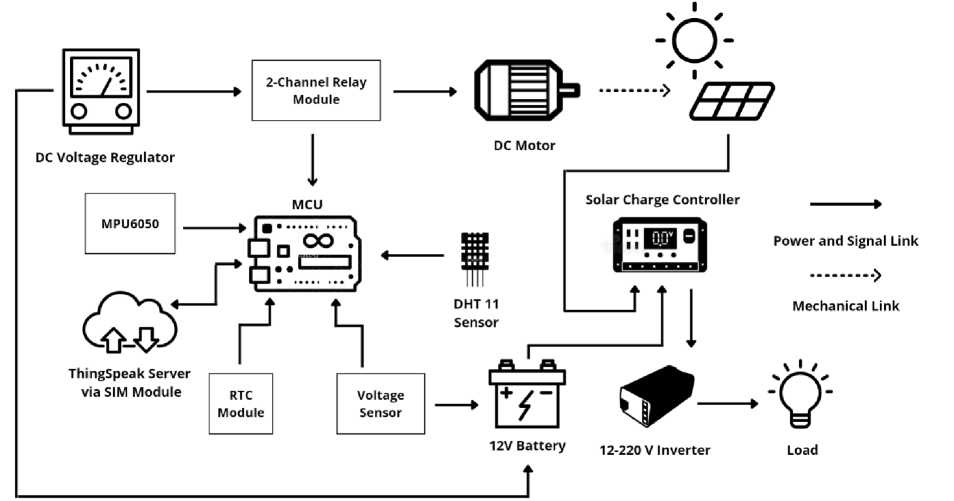
Fig. 2. Proposed System Design
Every two hours starting from the 7 AM position, the MCU will calculate the relative Azimuth and elevation angle of the Sun at that time. If the values are within the range, then the relay will trigger and rotate the motor in the relevant direction. Once the panel has adjusted to the angle, the relay will turn off and the MCU will send the gathered data to the ThingSpeak server via the connected GSM network. The purpose of the custom-designed DC Voltage Regulator circuit is to reduce the voltage and current supplied to the motor from the 12V battery connected (this is for controlling the speed of panel rotation).
The DHT11 temperature and humidity sensors are placed, and the measured values will be sent to a configured ThingSpeak Server via the SIM Module linked with the MCU along with the present voltage of the battery at the time. The user can then visualize this data as graphs on the Server. Finally, a load such as a 40W bulb or water pump can then be driven via the 12V-220V PCB design inverter circuit. It is based on CD4047 multivibrator IC and a DC auxiliary circuit 10v Zener to control if battery voltage drops less than 9V the inverter should stop. To increase power and amplify the voltage level of the waveform, complementary symmetry amplifiers consisting of transistors BC 337 and TIP 3055 are used.
5. Experiments and Results
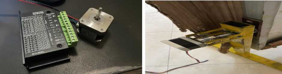
The solar panel is approximate of weight 5kg with a length of 74cm, a width of 3cm, and a height of 64cm. Initially, a test was carried out using NEMA 17 Stepper motor with a Microstep Driver as shown in Fig.3(a). below, but unfortunately even after mounting it with bracket and bearing it was unable to produce enough torque to turn the panel. Also, the locking mechanism (brake) wasn’t sufficient to stop the panel from rotating if a small force was applied to it which may alter the position of the panel and defeat the purpose of Solar tracking. In the case where the system loses power, the stepper motor brake releases and is freely able to turn.
(a)
(b)
(c) (d)
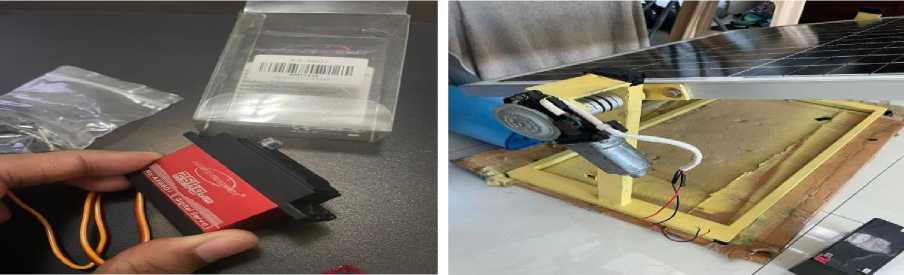
Fig. 3. (a): NEMA 17 Stepper Motor + Microstep Driver, (b): NEMA 17 Stepper Motor, (c): Austarhobby AX8601 Servo Motor, (d): DC Car Window Motor
A similar scenario to the above was seen when using an Austarhobby AX8601 Servo Motor Fig.3(c). as its braking feature goes away once power is lost. It would have been possible to rotate the panel but the shaft on it was too small and required adding a lathing process to properly mount the motor to the panel with the bracket which is a costly process. To overcome the locking/ braking problem, a 12V DC car window motor Fig.3(d). was used to rotate the panel.
When force is applied, it successfully locks on its current position and can withstand it without drastically altering the position of the panel. Since it’s a DC motor the only issue regarding it was to program to which position, we want the panel to be rotated. But it can still be possible by adding another module such as MPU6050 gyroscope to measure the angles (as the panel rotates about its position, only the Y and Z -Axis change but not the X-Axis) at which we want the panel to be at these specific times corresponding with the relevant angles of the Sun. Furthermore, supplying 12V directly to the motor wasn’t going to be helpful as it will produce even more torque in which the panel will begin rotating at a high speed. A custom-designed DC Voltage Regulator Circuit was made to alter the voltage to a lower value and adjust the rotation speed in which the supplied current to the motor could be controlled as well.
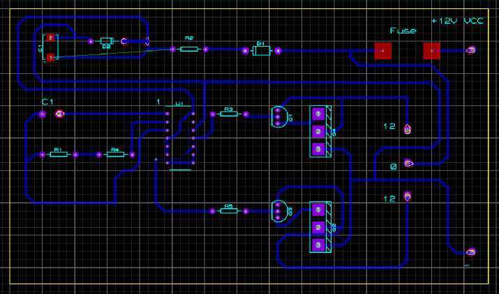
Fig. 4. PCB Schematic for 12-220V Inverter Circuit
When powering electronics and electrical equipment qualified for the ac mains voltage, an inverter converts dc power sources into an ac voltage. They are also commonly employed in the inverting stages of switched-mode power supply. The waveform, frequency, and output waveform of the circuits are categorized together with the switching technology and switch type. In the DC auxiliary circuit Fig.4., a 10v Zener is used to control if the battery voltage ever falls below 9V at which then the inverter stops functioning. Once the inverter starts, the battery voltage will gradually begin to drop. A 150-ohm resistor is used if there’s a drop in voltage from 12V to 10V and when the IC circuit receives less than 9V, the inverter will stop which is why a 10V Zener was used.
The IN4001 diode is used to block any reverse voltage once the inverter functions as it can get some negative voltage also it will be protected if there was a change in polarity. The IC has two output pins 10 and 11 which are used for negative square wave and positive square wave to complete one cycle where a half cycle is 10ms and a full cycle is 20ms in 50Hz. Resistor and capacitor pin 1,2 and 3 calls an RC network to set the frequency to 50Hz. All the IC input pins which are not used will be bridged to the ground otherwise a floating IC will not work to provide a proper output. BC 337 is a driver transistor that is used as the TIP 3055 cannot switch on from an IC output due to the need for a high gain, so a driver transistor is used in place to switch the TIP3055. BC337 is the high gain transistor that can switch on with 1mV. The TIP3055 transistor needs 5mV to switch on. As the IC cannot provide that output, a driver transistor is used to switch the big transistor. Once the driver switches on, it will be grounded by the emitter which then the TIP3055 will switch on.
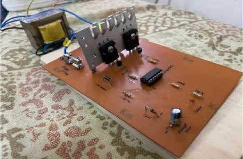
Fig. 5. Manufactured PCB
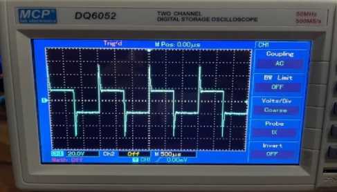
Fig. 6. Oscilloscope output from manufactured PCB
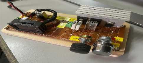
Fig. 7. DC Voltage Regulator
Since it was utilizing a 12V DC motor, supplying 12V directly from the battery would make the motor rotate at a very high speed which isn’t required. To overcome this, I have made a modification of the 12V DC Voltage Regulator circuit in which the current can be adjusted as well to control the speed at which the motor rotates as shown in Fig.7. The ideal voltage was set to be at 5V for which the panel begins to rotate at a reasonable speed.
An I-V curve can be used to describe how a solar cell behaves when it is lit. The I-V curve remains unchanged even when many solar cells are connected in series or parallel to create solar panels, increasing the overall voltage and/or current. The temperature and irradiance of the module affect the I-V curve. Increased current and slightly elevated voltage result from an increase in irradiance. The voltage is negatively impacted by rising temperatures since the voltage tends to drop.
The specific voltage and current at which a PV module runs at any given time are referred to as the module's operating point. The operating point relates to a certain (I, V) pair that lies on the I-V curve for a given irradiance and temperature. The power-voltage (P-V) curve's operational point (I, V) corresponds to that point. The operational point, also known as the maximum power point (MPP), should be chosen to match the maximum of the (P-V) curve to produce the most power output at a given irradiance and temperature. The MPP, however, is reliant on the surrounding circumstances. The I-V and P-V properties will alter with a change in temperature or irradiance, which will also cause a change in the MPP's position. To adjust the operating point to the MPP after changes in the ambient circumstances, changes in the I-V curve must be continuously monitored [16].
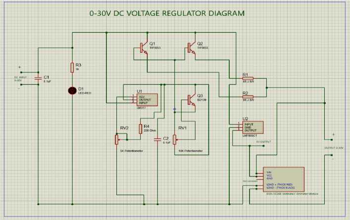
Fig. 8. Custom DC Voltage Regulator Circuit
Voltage and current in solar panels are affected by temperature. The quantity of energy a panel produces decreases as the temperature rises. High temperatures cause an increase in resistance, which reduces the electrical current's speed. Similar to how resistance lowers as temperature rises, energy production increases [17].
The experimental process consisted of placing the system in an outside environment and allowing the custom made MCU circuit Fig.9. to run the system accordingly by retrieving the current date/time from the RTC module and calculating the respective Sun Altitude and Azimuth angle to determing the position in that particular day. Once its 5PM the sunlight isn’t very sufficient to produce solar energy therefore the system will be reset back to its original position. With the calculated angles the system will begin to adjust the position of the panel accordingly.
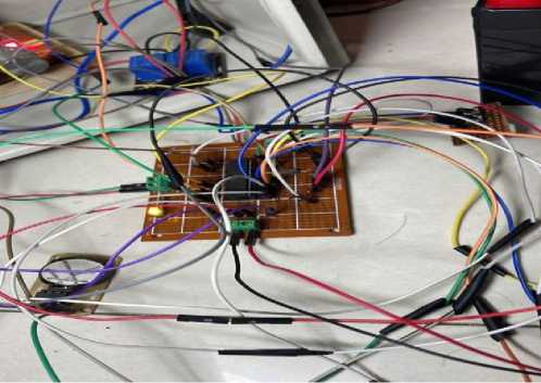
Fig. 9. Microcontroller Unit on Perfboard
The expectation of this process would be that the generated Solar Power should be improved compared with the fixed standalone system and via the custom made Inverter PCB to power up utilities efficiently by using the battery connected.
Tests were carried out on two consecutive days to find the efficiency of the Solar PV Voltage and Current using this solar tracking method and the fixed standalone method. The weather conditions on the first day were fairly sunny and on the second day was partially cloudy in the morning. Results have been plotted using MATLAB software and can be seen below:
A graph of the observed solar voltage for the fixed position Fig.10. can be visualized as the trend in voltage gradually begins to increase from 7 AM where it meets its peak values around 10 AM and begins to slowly decrease further on as the sun begins to set past midnight and the ambient temperatures increase. With the fixed position, a certain amount of sun rays will be missed due to the Sun movement throughout the day. The maximum Open-Circuit
Voltage (Voc) that the panel can produce is 22.3V at optimal environmental conditions therefore, explains the trend in measured Solar PV voltage values.
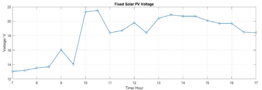
Fig. 10. Graph for Solar PV Voltage for Fixed Method
A graph of the observed solar current for the fixed position Fig.11. can be visualized as the trend in current gradually begins to increase from 7 AM where it meets its peak values around 1 PM and 2 PM and begins to slowly decrease further on. According to the panel specifications where the Operating Current (Imp) is at 2.73A at optimal environmental conditions, the resulting current was measured with the peak value of close to 0.5A.
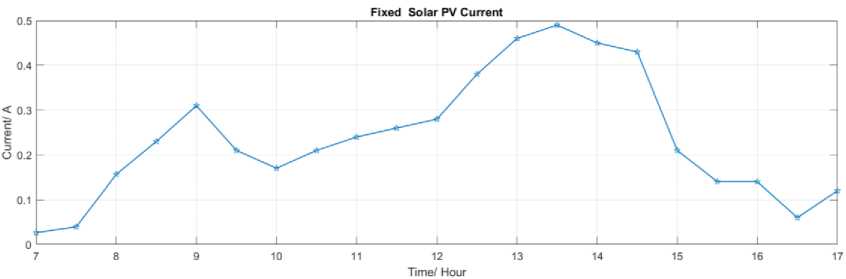
Fig. 11. Solar PV Current for Fixed Method
A graph of the solar output power for the fixed position Fig.12. can be visualized by multiplying the values of voltage and current obtained above, the trend in power gradually begins to increase from 7 AM where it meets its peak values around 1 PM and 2 PM and begins to slowly decrease further on. If a higher wattage panel was used, more electricity it can produce.
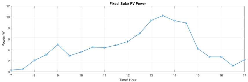
Fig. 12. Solar PV Power for Fixed Method
The graph of the observed Solar voltage via tracking method Fig.13. meets much higher peek values compared with the Fixed method from 7 AM onwards till 5 PM. As per panel specifications, the Open-Circuit Voltage (Voc) is at 22.3V in which via the tracking method the measured values come closer to that value at the peak point compared to the fixed method.
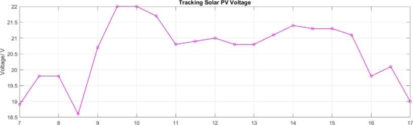
Time/ Hour
Fig. 13. Solar PV Voltage for Tracking Method
Higher current values are too observed via the Tracking method Fig.14. values compared with the Fixed method from 7 AM onwards till 5 PM. With the panel specification Operating Current (Imp) at 2.73A, the results appear much closer to the optimal value at the peak point compared with the Fixed method.
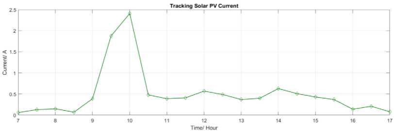
Fig. 14. Solar PV Current for Tracking Method
The results of peak values for Solar power output Fig.15. are much more values compared with the Fixed method from 7 AM onwards till 5 PM. The Max Power (Pmax) which can be generated by the panel at optimal environmental conditions is 50W, therefore it can be observed that the values correspond at peak point.
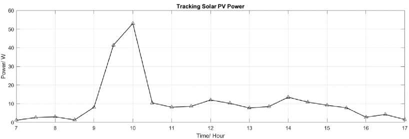
Fig. 15. Solar PV Power for Tracking Method
It can be distinguished by comparing results from Figures 10,11 and 12 with Figures 13,14 and 15 that the overall solar power output from the panels is greater with the Tracking method. There are trends in voltage and current scales in which points may seem like outliers but that is due to the clouds at the time.
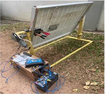
The Solar Panel setup is shown in Fig.16 tested in an outside environment.
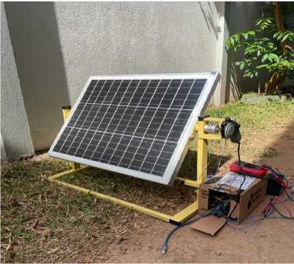
Fig. 16. Outside testing
6. Conclusions and Future Suggestions
This paper proposed a cost-effective and automated solar power system for farms in rural areas.Electricity is a crucial part of our daily lives. It consumes many of Earth's natural sources to produce this, which are currently depleting at a crucial rate and adding up to the global warming issue. Therefore, solar power would be one of the best alternatives to cope with the crisis, but this comes at a cost when maintaining the panels. When the panel is in fixed mounted position dust can be deposited but rotating the position of the panel can be avoided the collection of dust. Also, it is proven that automating the Solar PV System reduces labor costs and works much more efficiently in harvesting sun rays into the panel rather than traditional stand-alone systems. To address this problem, it has been proposed to implement an IoT-based Wireless sensing Solar Power System Fig.2. which would include capabilities like automatically calculating the position of the sun according to the time of day and adjusting the panel accordingly. It advances the field from the current state of knowledge where solar tracking takes place either hourly or with the use of LDRs which has limitations such as low temperature stability and slow response. This project follows an alternate path by obtaining the current date and time from the RTC module, and determining the orientation of the panel by computing the Sun's altitude and azimuth angle, respectively.
References Design of an IoT-Enabled Solar Tracking System For Smart Farms
- “Types and Advantages of Solar Tracking System | Mibet Energy.” https://www.mbt-energy.com/news/industry/2203041.html (accessed Sep. 21, 2022).
- S. Chakrabarti, “Types of Solar Trackers and their Advantages & Disadvantages,” SolarFeeds Magazine, Oct. 07, 2021. https://www.solarfeeds.com/mag/solar-trackers-types-and-its-advantages-and-disadvantages/ (accessed Sep. 21, 2022).
- S. Kyi and A. Taparugssanagorn, “Wireless sensing for a solar power system,” Digit. Commun. Netw., vol. 6, no. 1, pp. 51–57, Feb. 2020, doi: 10.1016/j.dcan.2018.11.002.
- Al-Farabi Kazakh National University, B. E. Yeszhanov, A. B. Salmen, and Al-Farabi Kazakh National University, “DEVELOPMENT OF AN AUTOMATED PHOTOVOLTAIC SYSTEM WITH WIRELESS MONITORING,” Kazakhstan Zool. Bull., vol. 2, no. 2, pp. 75–84, 2021, doi: 10.54944/kzbpn861rx98.
- M. E. Andreoni Lopez, F. J. Galdeano Mantinan, and M. G. Molina, “Implementation of wireless remote monitoring and control of solar photovoltaic (PV) system,” in 2012 Sixth IEEE/PES Transmission and Distribution: Latin America Conference and Exposition (T&D-LA), Montevideo, Sep. 2012, pp. 1–6. doi: 10.1109/TDC-LA.2012.6319050.
- A. Waleed et al., “Solar (PV) Water Irrigation System with Wireless Control,” in 2019 International Symposium on Recent Advances in Electrical Engineering (RAEE), Islamabad, Pakistan, Aug. 2019, pp. 1–4. doi: 10.1109/RAEE.2019.8886970.
- F. Al-Naima and A. Hamad, “A Low-cost Solar Farm Monitoring System Based on Cloud Database,” p. 5, 2018.
- R. Murugesh, A. Hanumanthaiah, U. Ramanadhan, and N. Vasudevan, “Designing a Wireless Solar Power Monitor for Wireless Sensor Network Applications,” in 2018 IEEE 8th International Advance Computing Conference (IACC), Greater Noida, India, Dec. 2018, pp. 79–84. doi: 10.1109/IADCC.2018.8692105.
- A. A. Rizvi, K. Addoweesh, A. El-Leathy, and H. Al-Ansary, “Sun position algorithm for sun tracking applications,” in IECON 2014 - 40th Annual Conference of the IEEE Industrial Electronics Society, Dallas, TX, USA, Oct. 2014, pp. 5595–5598. doi: 10.1109/IECON.2014.7049356.
- S. Akhlaghi, M. Sarailoo, M. Rezaeiahari, and H. Sangrody, “Study of sufficient number of optimal tilt angle adjustment to maximize residential solar panels yield,” in 2017 IEEE Power and Energy Conference at Illinois (PECI), Champaign, IL, USA, Feb. 2017, pp. 1–5. doi: 10.1109/PECI.2017.7935747.
- “The Sun’s Position | PVEducation.” https://www.pveducation.org/pvcdrom/properties-of-sunlight/the-suns-position (accessed Sep. 21, 2022).
- “How to design a Solar PV system (Estimation of net monthly insolation) – Sri Lankan Dream.” https://lankantrailblazer.wordpress.com/2019/10/04/how-to-design-a-solar-pv-system-estimation-of-net-monthly-insolation/ (accessed Sep. 21, 2022).
- “Solar elevation angle (for a day) Calculator,” High accuracy calculation for life or science. https://keisan.casio.com/exec/system/1224682277 (accessed Sep. 21, 2022).
- “GSMA | Narrowband – Internet of Things (NB-IoT) | Internet of Things.” https://www.gsma.com/iot/narrow-band-internet-of-things-nb-iot/ (accessed Sep. 21, 2022).
- “Advantages of NB-IoT | disadvantages of NB-IoT.” https://www.rfwireless-world.com/Terminology/Advantages-and-Disadvantages-of-NB-IoT.html (accessed Sep. 21, 2022).
- “Understanding the Voltage – Current (I-V) Curve of a Solar Cell.” https://www.electricalengineeringtoolbox.com/2021/12/the-behavior-of-illuminated-solar-cell.html (accessed Sep. 21, 2022).
- Premium, “How Does Temperature Affect Solar Panel Energy Production?,” Ilum Solar, Mar. 05, 2021. https://ilumsolar.com/how-does-temperature-affect-solar-panel-energy-production/ (accessed Sep. 21, 2022).
