Design of Decentralized Fuzzy Logic Load Frequency Controller

Author: K. A. Ellithy, K.A. El-Metwally
Journal: International Journal of Intelligent Systems and Applications(IJISA) @ijisa
Article in issue: 2 vol.4, 2012.
Free access
This paper presents a novel approach for designing a decentralized controller for load frequency control of interconnected power areas. The proposed fuzzy logic load frequency controller (FLFC) has been designed to improve the dynamic performance of the frequency and tie line power under a sudden load change in the power areas. The effect of generation rate constraint (GRC) for both areas has been considered in the controller design. The proposed FLFC consists of two internal fuzzy logic controllers namely, the PD-like fuzzy logic controller and the PI-like fuzzy logic controller. The FLFC has been co-coordinated with the conventional integral controller. Time-domain simulations using MATALB/SIMULINK program has been performed to demonstrate the effectiveness of the proposed FLFC. The simulation results show that the proposed FLFC can provide good damping and reduce the overshoot even in the presence of the GRC.
Load Frequency Control, Generation Rate Constraints, Conventional Integral Control, Fuzzy Logic Control.
Short address: https://sciup.org/15010104
IDR: 15010104
Text of the scientific article Design of Decentralized Fuzzy Logic Load Frequency Controller
Published Online March 2012 in MECS
Large-scale power systems are normally composed of control areas or regions representing coherent groups of generators. The various areas are interconnected through tie lines. The tie lines are utilized for energy exchange between areas and provide inter-area support in case of abnormal condition [1-5]. Area load-changes and abnormal conditions, such as outages of generation, leads to mismatch in scheduled power interchanges between areas. These mismatches have to be corrected via supplementary control. In recent years, large tie-line power fluctuations have been observed as a result of increased system capacity and very close interconnection among power systems [1]. This observation suggests a strong need of establishing a more advanced load frequency control (LFC) scheme. LFC is one of the major requirements in providing reliable and quality operation in interconnected power systems. The primary objectives of the LFC in an interconnected power system are to regulate the frequency to the nominal value and to maintain the interchange power between control areas at scheduled values by adjusting the MW output power of the selected generators so as to accommodate changing in load demands [4].
Many investigations in the area of LFC problem have been reported and a number of control strategies have been employed in the design of load frequency (LF) controller in order to achieve better dynamic performance [6-8, 9-15]. In recent years, fuzzy system applications have received increasing attention in power system operation and control [16, 17, 19, 24]. Fuzzy logic based controllers have been suggested as an appropriate choice to control non-linear system [17,18, 20] and are being investigated as an alternative to conventional control. The basic feature of fuzzy logic controllers (FLCs) is that the control strategy can be simply expressed by a set of rules which describe the behavior of the controller using linguistic terms. Proper control action is then inferred from this rule base. In additional, FLCs are relatively easy to develop and simple to implement. In the design of load frequency controller, it should be recognized that there is a limit to the rate at which generating unit outputs can be changed. This is particularly true of steam generating units where mechanical and thermal stress are limiting factor. The controller designed for unconstrained situation may not be suitable. The analysis performed in [11, 21] indicate that with constraints imposed by generation rate constraints (GRC), the dynamic responses of the power area experience larger overshoots and longer settling times, compared to the case without considering the GRC.
This paper presents a design for LF controller to improve the dynamic performance of power areas under disturbances such as a sudden load changes. The generation rate constraint (GRC) has considered in the controller design. The paper is organized as follows: Section 2 provides the model of the power two-area. Section 3 shows the designed fuzzy controllers. The effectiveness of the proposed controller on the dynamic performance is also contained in Section 4. The conclusions are given in Section 5.
-
II. MODEL OF TWO POWER AREA
Fig. 1 shows the block diagram representing the two area power system. This model includes the conventional integral controller gains (K 1 , K 2 ) and the two auxiliary (stabilizing) signals (Δu 1, Δu 2 ). The stabilizing signals will be generated by the proposed fuzzy logic load frequency controller (FLFC). Each power area has a number of generators which are closely coupled together so as to form a coherent group, i.e. all the generators respond in unison to changes in the load. Such a coherent area is called a control area in which the frequency is assumed to be the same throughout in static as well as dynamic situation [1, 4]. It is conveniently assumed that each control can be represented by an equivalent generator, governor and turbine system. The conventional LF controller shown in Fig. 1 is based upon tie-line bias control, where each control area tends to reduce the Area Control Error (ACE) to zero. The ACE given in (1) for each area consists of a linear combination of frequency and tie-line power deviation [2].
ACE i = £ ( A P > + r , A f ) (1)
j = 1
An overall satisfactory performance is achieved when у i is selected to be equal to the frequency bias factor of that
ACE 1 = A P 12 + B 1 A f 1
ACE, A P. + B, A f,
2 21 2 2
The ΔP 12 ( ΔP tie ) is the tie-line power deviation. The nomenclature used and the parameters values of the two power area are given in the Appendix.
There exists a maximum on the rate of change of power that can be generated by steam plants. The constraints of the nonlinear characteristics of the turbine control should be considered in the load frequency controller design. If these constraints are not considered in the controller design, the power area is likely to chase large monetary disturbance. The controller designed for the unconstrained situation may not be suitable. The analysis performed in [21] indicate that with constraints imposed by generation rate constraints (GRC), the dynamic responses of the power area experience larger overshoots and longer settling times, compared to the case without considering the GRC. Moreover, if the parameters of the controller are not chosen properly, the power area may have unacceptable dynamic response (large overshoot and long settling time) or become unstable. In the time-domain simulations presented in this paper, the linear model of turbine shown in Fig. 2 is placed by a nonlinear model shown in Fig. 6. This replacement is done to take into account the effect of GRC that emulates the practical limit on the response of
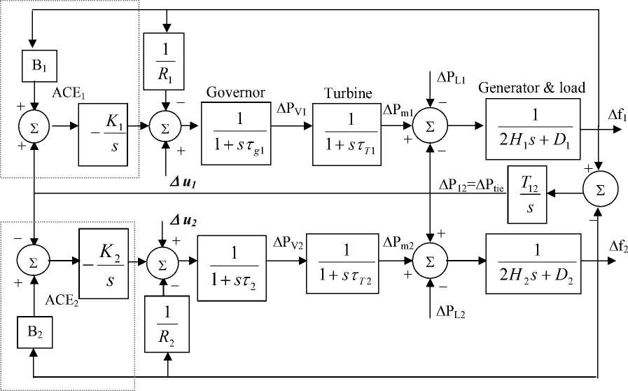
Fig. 1 Block diagram of Load frequency control (LFC) of two-area
area. So Y = B = — + D ii i
Ri
Thus, the ACEs for a two-area are the turbine [11, 21].
The system response having the integral controller gains (K1, K2) usually satisfies the desired objectives of the LFC (ensures zero frequency error in the steady state). The only problem of conventional integral controller is that the system response is less damped and the overshot is large. To solve this problem, another control signals (Δu1, Δu2) are added to the system in presence of integral controller. These signals are derived from the proposed fuzzy logic controller.
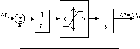
Fig. 2 Nonlinear Turbine model with GRC
-
III. Design of fuzzy logic load frequency
CONTROLLER
-
A. Introduction to Fuzzy Logic Control
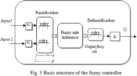
Fuzzy logic-based control (FLC) has been become an important methodology in control engineering and has been rapidly gaining popularity among engineers during the past few years [16-18, 20-25]. This increased popularity can be attributed to the fact that fuzzy logic provides a powerful vehicle that allows engineers to incorporate human reasoning in control algorithm. The fuzzy logic is used in system control design because it shortens the time for engineering development and sometimes in the case of highly complex systems is the only way to solve the problem. The basic configuration of a fuzzy-logic control is composed of four principle components: a fuzzification, a knowledge base, a inference engine, and defuzzification [20]. Figure 3 shows the basic configuration of a FLC.
formalized
Membership
The fuzzifier maps the input crisp values into fuzzy variables using normalized membership functions and input gains. The fuzzy logic inference engine then infers the proper control action based on the available rule-base. The fuzzy control action is translated to the proper crisp value through the defuzzifier using normalized membership functions and output gains.
-
B. Fuzzy logic load frequency controller design
To achieve these two goals the FLFC is designed to have two fuzzy logic controllers working in parallel. The first is a PD-like fuzzy logic controller which uses the frequency deviation, Δf, and the rate of the frequency deviation Δ 2 f, in order to enhance the transients of the frequency deviation of each area. The second is a PI-Like fuzzy logic controller which uses the frequency deviation, Δf, and the tie power deviation, ΔP tie , to reset the tie power to zero. The use of the ∆f and ∆f2 for a PD like is chosen basically to add a D component to the convention I-controller and thus improving the ∆f transient behavior. However, this component alone is not enough to provide good ∆Ptie behavior especially at the steady state value. This created the need to use a PI-like fuzzy controller using the ∆f and ∆P tie signals to ensure zero power in the tie line after disturbance.
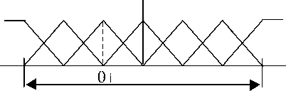
The output control signal from the FLFC, U f , is injected to the summing point of the designated area as shown in Fig. 5. Introducing fuzzy logic control means introducing a non-linear controller. In this case integral control alone will not provide a complete reset to the error. This is the reason for providing a rest term using the fuzzy PI-Like controller. The PD-fuzzy controllers have been applied alone but they didn’t give a good response for the tie-line power. Each input or output of both the PD and the PI like fuzzy controllers, (fuzzy variable, X = {Δf, Δ 2 f, ΔP tie , U pd , U PI }), is assigned seven linguistic fuzzy subsets varying from, Negative Big (NB) to Positive Big (PB). Each fuzzy subset is associated with a triangular membership function to form a set of seven normalized and symmetrical triangular membership functions for each fuzzy variable, see Fig. 4.
NB NM NS Z PS PM PB
X min X range X max
Fig. 4 Fuzzy variable, Xi, Seven membership functions
The X max and X min represent maximum and the minimum variation of the input and output signals. These values are selected based on simulation information. The selected value of X max and X min was based on the performed dynamic simulations under different system operating conditions including different load changes to obtain a robust modulated signal (output signal of the designed FLFC controller) which improve the dynamic performance (reducing the overshoot and improving the damping) of the system under diffent operating conditions and system parameters change. The range of each fuzzy variable is normalized between –1 to 1 by introducing a scaling factor to represent the actual signal so that:
achieved by integrating the output of a PD-Like controller [18]. Thus the final configuration of the proposed FLFC is shown in Fig. 5. A symmetrical fuzzy rule set is used to describe both the PD and the PI like fuzzy controller behaviors as shown in Table 1 and 2. The fuzzy rules have been selected based on experience gained form different simulations.
The PD-Like fuzzy controller initial gains are given by [17, 18]:
K Δ f =
Δ f max
; K Δ 2 f
max
; K upd
= U
pd max
Similar definition applies in the case of the PI-like fuzzy controller
K Δ f =
Δ f max
; KP tie
Δ P tie max
; K upi
= U
pi max
Where K Δ f , KP tie , K upi are the gains of frequency deviation, tie power deviation, and the output control signal respectively. While , Δ f max , Δ P tiemax , U pimax are the maximum deviation in frequency, tie-line derivative and max control limit respectively. These gains are actually scaling factors to adapt input signal to the normalized fuzzy membership functions. The reason of using the inverse of the signal expected maximum value is to provide full coverage of the membership functions range and thus utilizing the complete rule base. The values of maximum variation of the input and output signals (∆f max , ∆f max , ∆P tiemax ) can be easily found from the system simulations under disturbances [7]. These initial gains can be further tuned slightly to achieve better performance. The PI-like fuzzy control action can be
Table 1: PD-Fuzzy Logic Rules
|
Δf |
Δ2f |
||||||
|
NB |
NM |
NS |
Z |
PS |
PM |
PB |
|
|
NB |
NB |
NB |
NB |
NB |
NM |
NS |
Z |
|
NM |
NB |
NB |
NM |
NM |
NS |
Z |
PS |
|
NS |
NB |
NM |
NM |
NS |
Z |
PS |
PM |
|
Z |
NM |
NM |
NS |
Z |
PS |
PM |
PM |
|
PS |
NM |
NS |
Z |
PS |
PM |
PM |
PB |
|
PM |
NS |
Z |
PS |
PM |
PM |
PB |
PB |
|
PB |
Z |
PS |
PM |
PB |
PB |
PB |
PB |
Table 2: PD-Fuzzy Logic Rules
|
Δf |
ΔP tie |
||||||
|
NB |
NM |
NS |
Z |
PS |
PM |
PB |
|
|
NB |
NB |
NB |
NB |
NB |
NM |
NS |
Z |
|
NM |
NB |
NB |
NM |
NM |
NS |
Z |
PS |
|
NS |
NB |
NM |
NM |
NS |
Z |
PS |
PM |
|
Z |
NM |
NM |
NS |
Z |
PS |
PM |
PM |
|
PS |
NM |
NS |
Z |
PS |
PM |
PM |
PB |
|
PM |
NS |
Z |
PS |
PM |
PM |
PB |
PB |
|
PB |
Z |
PS |
PM |
PB |
PB |
PB |
PB |
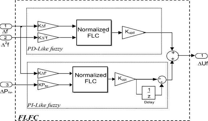
Fig. 5 The structure of the proposed FLFC
Each entity in the table represents a fuzzy rule of the from "if antecedent then consequence", e.g. the shaded rule in Table 1 is if Af is NB and A2 f is PB then Upd is Z (5)
Defuzzification is achieved using the center of gravity method [20]. In general, if the control output membership functions centroids are represented by θ1,…,θM. Thus, for M rules, the crisp output of the controller is:
M
У wA u=-^M— =A z_
У w i=i
Where
_ = [ _ i„.. _ , .„. _ m ]
w i
_ i M
Ъ wk k = 1
.
The strength of the ith is w i and it is calculated based on interpreting the ‘and’ conjunction as a product of the membership values corresponding to the measured values of A f and A 2 f For example, the rule strength of the
W = M nb (a f ) x M ps ( A f ) (7)
where ^(x) is the membership value of the fuzzy variable, x.
The net control action ( U f ) of the FLFC is the sum of the individual PD and PI-like fuzzy controller outputs ( U pd , U pi ) thus:
U f = U pd + U p, (8)
-
IV. Computer Simulation Results
The block diagram of the simulated model of the two area system is given in Fig. 6. The system is controlled by using: a) conventional integral controller; b) propose FLFC. The effects GRC for both areas have been included in the simulations. The GRC is taken into account by adding a limiter to turbine as shown in Fig. 6. The values ± 0.2 are considered for the limits. In addition, to prevent the excessive control action, a limiter is also added to the integral control part. The simulations have been performed for the following two cases:
shaded rule in table 1 is given by (7)
B1
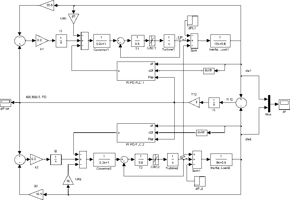
Fig. 6 Simulink Block diagram of LFC of two-area including GRC
Case 1: Simulations result with conventional integral controller
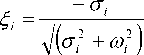
In this paper, the integral controller gains ( K 1 , K 2 ) have been determined using eigenvalue analysis. Satisfactory system transient response can be achieved by improving the relative damping (damping factor) of the dominant eigenvalue modes associated with the frequency deviations. The common index for system damping is the relative damping of the dominant modes. The relative damping of a complex eigenvalues λ i = σ i ± jω i is given by (9).
|
Δf 1 |
ΔP c1 |
ΔP m1 |
ΔP v1 |
ΔP 12 |
Δf 2 |
ΔP c2 |
ΔP m2 |
ΔP v2 |
|
|
X |
0.1075 |
0.1624 |
0.7266 |
0.0028 |
0.0006 |
0.0000 |
0.0000 |
0.0000 |
0.0000 |
|
X |
0.0000 |
0.0000 |
0.0000 |
0.0000 |
0.0018 |
0.1414 |
0.2281 |
0.6235 |
0.0052 |
|
^ 3 |
0.4198 |
0.3091 |
0.1483 |
0.0336 |
0.0259 |
0.0283 |
0.0199 |
0.0126 |
0.0025 |
|
^ 4 |
0.4198 |
0.3091 |
0.1483 |
0.0336 |
0.0259 |
0.0283 |
0.0199 |
0.0126 |
0.0025 |
|
r , |
0.0449 |
0.0319 |
0.0151 |
0.0034 |
0.0383 |
0.3918 |
0.2719 |
0.1681 |
0.0345 |
|
^ 6 |
0.0449 |
0.0319 |
0.0151 |
0.0034 |
0.0383 |
0.3918 |
0.2719 |
0.1681 |
0.0345 |
|
r , |
0.0488 |
0.0660 |
0.0250 |
0.1214 |
0.2880 |
0.0510 |
0.0921 |
0.0436 |
0.2641 |
|
X , |
0.0488 |
0.0660 |
0.0250 |
0.1214 |
0.2880 |
0.0510 |
0.0921 |
0.0436 |
0.2641 |
|
Г 9 |
0.0480 |
0.0026 |
0.0010 |
0.6371 |
0.0000 |
0.0206 |
0.0007 |
0.0003 |
00 .2987 |
where ω i characterizes the frequency and σ i the damping behavior of oscillations.
Participation factors technique [4, 26], can be used to associate state-variables (frequency deviation Δf i = 0, i=1,2 ) with the specific modes (dominant eigenvalues modes X 3 ,4 & X 5, 6). The participation factors P ki is defined as :
Pk. = n v ik H W ki I (10)
E ЫЫ
= 1
where vik and wik are the kth entries of the right and left eigenvector associated with λ i . The P ki provide a measure of the contribution of kth state variable to the ith eigenvalue and so can be used to correlate the contribution of each state variable to each eigenvalue mode The system eigenvalues are listed in Table 3. The table clearly show that the system is stable at 0.3 gains setting (all eigenvalues having negative real part) while the system is unstable at 0.8 gains setting.
Table 3: System Eigenvalues with integral controller
|
Eigenvalues X i |
Stable ( K 1 =K 2 =0.3) |
Unstable (K 1 =K 2 =0.8) |
|
X 1 |
-5.8468 |
-5.788 |
|
X 2 |
-4.2717 |
-4.1894 |
|
X 3,4 |
-0.3768 ± 1.7234i * |
-0.0912 ± 1.7122i |
|
X 5,6 |
-0.2231+ 1.5992i ** |
0.0287 ± 1.5766i |
|
X 7,8 |
-0.2537 + 0.0484i |
-0.2216, -0.8494 |
|
X 9 |
-0.3468 |
-0.9992 |
*c34 of stable mode X 3 ,4 =21.3592%
**^ 5,6 of stable mode X 5 , 6= 13.8169%
The Participation factors have been calculated and the eigenvalues modes associated with the frequency deviations have been identified. The calculated participation factors are given as :
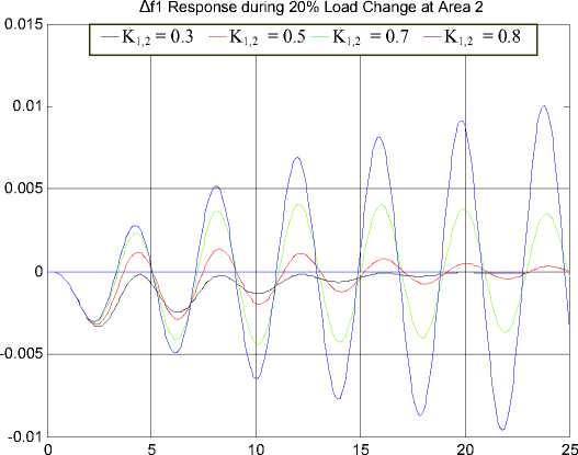
From the participation factors, it can be observed that the largest participation factor 0.4198 is associated with the eigenvalue modes X 3,4 while the largest participation factor 0.3918 is associated with the modes X 5,6. Figures 7 and 8 show the system frequency response with different values of integral controller gains K1 = K2 = K1,,2 under 20% and 1% changes in the load demand at area 2. From Fig. 7 and 8, it can be seen that the gains K1 = K2 = K1,,2=0.3 gives the best damping response. From Table 3 and the time response shown in Figs. 7 and 8, it can be seen that the higher gains of integral controller can lead the system to instability. The results have shown that the system becomes unstable at K1,,2≥ 0.74. Optimization technique presented in [12] can also be applied to determine the optimal integral controller gains.
-
Case2: Simulations Result with the proposed fuzzy logic frequency controller
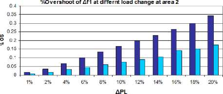
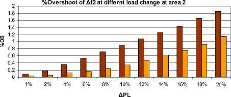
From the system dynamic response shown in Figs.7 and 8, it can be seen that the conventional integral controller provide zero frequency deviations (Δfi=0, i=1,2) in the steady-state but it exhibits poor dynamic performance; i.e. it exhibits large overshoot and less damping [1, 9]. In order to improve frequency damping (i.e. ensures zero frequency deviations in shortest time possible) and to reduce the frequency overshoot whenever there is any disturbance. the fuzzy logic frequency controller (FLFC) is proposed. To demonstrate the effectiveness of the proposed FLFC compare to the conventional integral controller, timedomain simulations of the two area power system have been performed under disturbances (1% and 5% load changes). Similar responses were obtained for load disturbance applied to area 2 as shown in Figs. 9-12. Figures 9-12 show the system dynamic response for both 1% and 5% load change. From Figs. 9-12, it can be seen that the dynamic response of the frequency and tieline deviations is less damped (large settling time) and large overshoot with only the integral controller for both disturbances. On the other hand the dynamic response of the frequency and tie-line deviations is well damped and the overshoot (%OS) is reduced with the proposed FLFC controller for all disturbances considered. The improvements in %OS are shown in Figs. 14 and 15. This proves that the designed decentralized FLFC controller is more effective controller in reducing system overshoot and decreasing the settling time. The proposed controller still yields good dynamic performance for both areas when the GRC is included.
The disturbance matrix Г equals to
r- 2H 1 = 0
T
-
Case3: Simulations results with the optimal load frequency controller
The proposed FLFC has also been compared with the optimal controller determined by the LQR technique [9,10] and it is found that the FLFC the proposed FLFC can achieve better dynamic performance than the optimal controller as shown in Fig. 13. The state space model of the two-area under study and the designed optimal statefeedback gains determined by LQR are given as follows:
-
A. State-variable model
The state-space equations of the linear time-invariant of the two power areas:
A x = A A x + B A u ■ IV’ (11)
A y = C A x
Where:
-
B. Optimal load frequency controller
The optimal controller is design to minimize the quadratic performance index of the following form :
J = J (A x T Q A x + A u T R A u ) dt (12)
Subject to the dynamic system equation in (11), Q is a positive semi-definite matrix and R is a positive definite matrix. The optimal gain vector is given by :
K = R - 1 B T P (13)
Where P is determined by solving the following Riccati equation :
PA + ATP - PBR - 1 BTP + Q = 0 (14)
The calculated optimal state-feedback gains are given as :
Ax=[Af AP AP AP1 AP Af AP2 AP, APT is the state variables vector.
86.8631
- 32.1644
K =
2.5342 0.7289 - 20.0053 1.6851 - 41.3502 - 1.2733 - 0.2936 12.1153
- 0.7891 - 0.1957 7.7316 - 0.6917 71.1184 3.0647 0.9946 - 17.8207
Δu = [Δu 1 Δu 2 ]T is the input vector .
|
A P l |
= И 1 |
A P L 2 ] is the disturbance to the system. |
||||||||
|
- D 1 2 H 1 |
1 2 H 1 |
0 |
0 |
- 1 2 H 1 |
0 |
0 |
0 |
0 |
||
|
0 |
- 1 T T 1 |
1 T T 1 |
0 |
0 |
0 |
0 |
0 |
0 |
||
|
R T g 1 |
0 |
T g 1 |
1 T g 1 |
0 |
0 |
0 |
0 |
0 |
||
|
- K . B . |
0 |
0 |
0 |
- K 1 |
0 |
0 |
0 |
0 |
||
|
A = |
T 12 |
0 |
0 |
0 |
0 |
- T 12 |
0 |
0 |
0 |
|
|
0 |
0 |
0 |
0 |
1 2 H 2 |
- D 2 2 H 2 |
1 2 H 2 |
0 |
0 |
||
|
0 |
0 |
0 |
0 |
0 |
0 |
- 1 T T 2 |
1 T T 2 |
0 |
||
|
0 |
0 |
0 |
0 |
0 |
0 |
1 |
||||
|
R 2 T g 2 |
T g 2 |
T g 2 |
||||||||
|
0 |
0 |
0 |
0 |
K 2 |
- K 2 B 2 |
0 |
0 |
0 |
||
|
B = |
0 0 |
1 T G 1 |
0 |
0 |
0 |
00 01 T G 2 |
0 |
T |
||
|
00 . |
0 |
0 |
0 |
0 |
0 |
|||||
Time [sec]
Fig. 7 Response of area 1 frequency deviation ∆f1due to 20% load disturbance at area 2 at different integral controller gains.
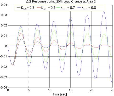
Fig. 8 Response of area 2 frequency deviation ∆f2 due to 20% load disturbance at area 2 at different integral controller gains
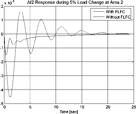
Fig. 11 Response of area 2 frequency deviation ∆f 2 due to 5% load dsiturbance at area 2 with GRC
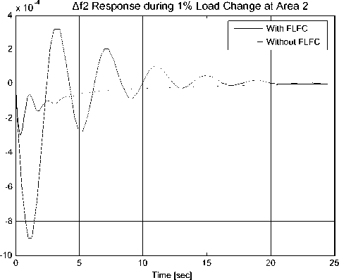
Fig. 9 Response of area 2 frequency deviation ∆f 2 due to1% load dsiturbance at area 2 with GRC
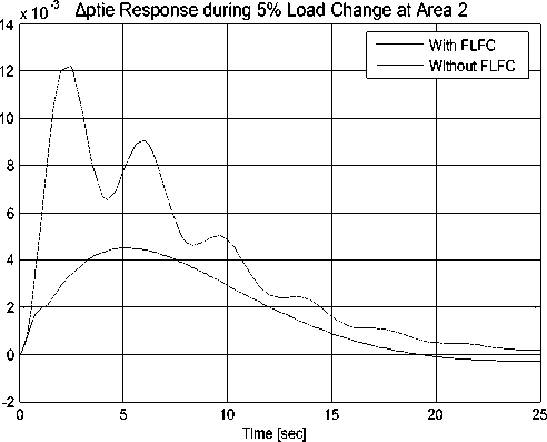
Fig. 12 Response tie‐line power deviation ∆P tie due to 5% load disturbance at area 2 with GRC
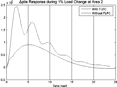
Fig. 10 Response tie-line power deviation ∆P tie due to 1% load disturbance at area 2 with GRC
Δf2 Response during 20% load change in Area 2
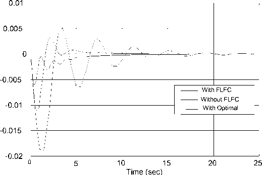
Fig. 13 Response of area 2 frequency deviation ∆f 2 due to 20% load disturbance at area 2
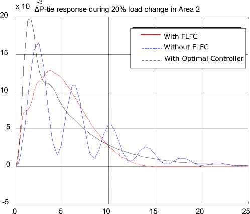
Fig. 14 Response of area 2 frequency deviation ∆P tie due to 20% load dsiturbance at area 2
■ Wthout FLFC eWth FLFC
Fig. 15 Percent overshoot of area 2 frequency deviation Δf1 under load disturbance at area 2
■ Wthout FLFC □ With FLFC
Fig. 16 Percent overshoot of area 1 frequency deviation Δf2 under load disturbance at area 2
-
V. Conclusions
A decentralized fuzzy logic frequency controller (FLFC) coordinated with conventional integral controller has been proposed to damp out the deviations of the frequency and tie-line power for the interconnected power areas and also to keep the interchanged power at the scheduled value. The proposed FLFC incorporate two fuzzy logic controllers a PD-fuzzy logic controller and the PI-fuzzy logic controller. The PD-fuzzy controller uses the frequency deviation and the rate of the frequency deviation in order to enhance the transients of the frequency deviation of each area while the PI-fuzzy logic controller uses deviations of the frequency deviation and the tie line power to enhance the transient of the tie line power deviation and keep power in the tie line to the scheduled value. The computer simulations results show that the proposed FLFC is more effective means for improving the dynamic performance of the two power area compared to the conventional integral controller. The proposed FLFC controller still achieves good dynamic performance when the GRC is considered and ensures the stability of power areas for all load demand changes. Moreover, the proposed controller type is relatively simple and suitable for practical on-line implementation.
References Design of Decentralized Fuzzy Logic Load Frequency Controller
- Fosha, C.E. and Elgerd, O.I., The megawatt-frequency control problem: a New Approach via Optimal Control Theory, IEEE Trans. Power Apparatus and Systems, 1970, 89(4): 563-577.
- Kothari, D.P. and Nagrath, I.J. Modern Power System Analysis, 1st Edition, McGraw-Hill, New York, 2008.
- Kundur P. Power System Stability & Control, McGraw-Hill, New York, 1994.
- Wood, A. Power Generation, Operation and Control, 2nd Edition, Prentice-Hall. New York, 1996.
- Shayeghi H, Shayanfar HA, Jalili A. Load frequency control strategies: a state of-the-art survey for the researcher. Energy Conversion and Management, 2009, 50(2): 344–353
- Tan W. Decentralized load frequency controller analysis and tuning for multi-area power systems, Energy Conversion and Management , 2011,52(5): 2015–2023.
- Al-Badi, M., Awlad Thani, A. Al-Omeiri, B. and Ellithy, K.A. Comparative Study of Load Frequency Controller Design for Interconnected Power Systems, The Journal for Scientific Research-Science and Technology, Sultan Qaboos University,m 2002 , 7: 81-90.
- Chan, W.C. and Hsu, Y.Y., Automatic Generation Control of Interconnected Power Systems Using Variable Structure Controller. IEE Proc. on Generation, Transmission and Distribution Pt. C, 1981: 269-279.
- Feliach, A. , Optimal Decentralized Load Frequency Control, IEEE Trans. on Power Systems, 1987, 2: 379-386.
- Hiyama, T., Design of Decentralized Load Frequency Regulators for Interconnected Power Systems, IEE Proc., Pt C, 1982, 129 (1): 17-23.
- Hiyama, T. Optimization of Discrete-Type Load Frequency Regulator Considering Generation Rate Constraints, Proc. IEE, Pt. C, Generation, Transmission and Distribution, 1982, 129 (6): 285-289.
- Kothari, M.L., Nanda, J., Kothari, D.P. and Das, D., Discrete-Mode Automatic Generation Control of Two-Area Reheat Thermal System with New Area Control Error, IEEE Transactions on Power Systems, 1989, 4(2): 730-738.
- Oysal, Y. A Comparative Study of Adaptive Load Frequency Controller Designs in a Power System with Dynamic Neural Network Models, Energy Conversion and Management 2005, 46 (15-16): 2656-2668.
- Yang, T.C., Ding. and Yu, H. Decentralized power system load frequency control beyond the limit of diagonal dominance, Electric Power Energy System, 2002, 24(3): 173–184.
- Yang, T., Cimen, H. and Zhu, O. Decentralized Load-Frequency Controller Design Based on Structured Singular Values,” IEE Proc. on Generation, Transmission and Distribution, 1998, 145(1):.7-13.
- Ellithy, K.A. and Al-Naamany, A. A Hybrid Neuro-Fuzzy SVC Stabilizers for Power System Damping Improvement in the Presence of Load Parameters Uncertainty, International Journal of Electric Power Systems Research, 2000, 56(3): 211-223.
- El-Metwally, K.A. and Malik, O. Fuzzy logic power system stabilizer, IEE Proc. Generation, Transmission, and Distribution, 1995, 142(3): 277-281.
- El-Metwally, K.A., A Fuzzy Logic Based PID for Power System Stabilization, Journal of Electric machines and Power Systems , 2001, 29(7): 659-668.
- Momoh, J. Ma, X Tomsovic, K. Overview and literature survey of fuzzy set theory in power systems, IEEE Trans. on Power Systems, 1995, 10(3): 1676 – 1690.
- Passino, K. and Yurkovickh, S., H. Fuzzy Control, Addison Wesley Longman, Inc., 1998.
- Moon, Y.H., Lee, H.S., Sung, J.G., and Shin, K.B. Extended Integral Control for Load Frequency Control with the Consideration of Generation-rate Constraints, Electrical Power and Energy Systems , 2002, 24(4): 263-269.
- İlhan K. and Ertuğrul. C. Fuzzy logic controller in interconnected electrical power systems for load-frequency control, International Journal of Electrical Power & Energy Systems, 2005, 27(8): 542-549
- Tang, K.S, Man K.F., Chen G. and kwong S., An Optimal Fuzzy PID Controller, IEEE Trans. on Industrial Electronics , 2001, 48(4) 757-765.
- Pothiya, S., Ngamroo, I., Runggeratigul, S. and Tantaswadi, P. Design of Optimal Fuzzy Logic Based PI Controller using Multiple Tabu Search Algorithm for Load Frequency Control, Journal of Control, Automation, and Systems, 2006, 4(2): 155-164.
- Talaq, J. and Albasri F. Adaptive Fuzzy Gain Scheduling for Load Frequency Control, IEEE Trans. on Power Systems, 1999, 14(1): 145-151.
- Perez-Arriaga, I.J., Verghese, G.C. Schweppe, F.C. Selective Modal Analysis with Applications to Electric Power Systems. Part I: Heuristic Introduction. Part II: The Dynamic Stability Problem, IEEE Trans. On Power Apparatus and Systems, 1982, 101: 3117-3134.
