Design of Dual Band Microstrip Patch Antenna for 5G Communication Operating at 28 GHz and 46 GHz

Author: Anurag Nayak, Shreya Dutta, Sudip Mandal
Journal: International Journal of Wireless and Microwave Technologies @ijwmt
Article in issue: 2 Vol.13, 2023.
Free access
The design of suitable compact antenna for 5G applications with superior return loss and bandwidth is still a fascinating task to the researchers. In this paper, the authors have designed a dual band microstrip patch antenna for 5G communications at 28 GHz and 46 GHz using CST studio. Rectangular patch antenna with double slots is considered to serve the purpose. The performance of the proposed patch antenna is very satisfactory in terms of return loss, VSWR, bandwidth and directivity. The values of S11 are well below -39dB and values of VSWR are very close to 1 for both resonance frequencies. The bandwidths for both cases are greater than 1.8 GHz which is an essential characteristic of 5G patch antennas for high speed connectivity and efficiency. Directivities are above 6 dB which are very suitable for the present problem. The simulation results are also compared with existing dual band 5G patch antennas and it has been observed that proposed antenna has outperformed the existing patch antennas that worked in 28GHz and 46GHz frequency range. The main advantage of this patch antenna is that it’s simple structure and good return loss, bandwidth and gain.
5G Antenna, Microstrip patch antenna, Dual band, Rectangular
Short address: https://sciup.org/15019210
IDR: 15019210 | DOI: 10.5815/ijwmt.2023.02.05
Text of the scientific article Design of Dual Band Microstrip Patch Antenna for 5G Communication Operating at 28 GHz and 46 GHz
There have been a lot of advancements [1] in wireless communication in the recent past, the latest of all is the 5G wireless communication. In 5G wireless communication, higher operating frequencies are normally preferred as compared to 4G which is above 24GHz. In 2015, the international telecommunications union discharged the potential millimeter-wave frequency band between 24 GHz to 84 GHz frequency at a global radio communication conference [2]. In the new era of exponential growth in internet users as well as incorporation of internet of things (IOT) into the daily lives of people, it is inevitable that 5G technology must be adopted in all modern devices. 4G technology could not fulfill these requirements due to bandwidth shortages. Furthermore, 5G communication systems feature higher bandwidth, higher bit rates, less energy consumption per unit of data (watt/bit), and better coverage, which is a necessity in this age of big data [3].
The researchers are working to design an antenna at 5G frequencies which has small size, greater bandwidth, lower return loss and higher directivity to provide better connectivity and efficiency in terms of the internet speed. Microstrip patch antenna can serve these purposes [4] which are compact and light weight in nature and can employed in real life systems for communication. Dual band microstrip patch antennas are drawing lots of attention as these antennas are compatible in two different frequencies which is definitely an advantage of using two separate antennas. The best way to design a dual-band antenna is by integrating two different frequency bands in single microstrip patch structure itself instead of using an antenna array of two, as it will be more cost and space effective [5].
In this paper, the researchers have come up with a simple rectangular slotted patch antenna (dual band) operating at frequency 28 GHz and 46 GHz (characterized with wider bandwidth of 1.84 GHz and 9 GHz respectively). The presented work is a rectangular microstrip patch antenna designed with two rectangular slots (semicircular at both the end) on it; loss free polycarbonate substrate is in use. The authors have also achieved satisfactory return loss, gain and VSWR. Now, the rest of the paper is structured as follows: Section 2 and Section 3 describe the literature survey and preliminary concepts on rectangular patch antenna respectively. Section 4 describes the different dimensions and structure of the proposed antenna. Next, output results (i.e. return loss, VSWR, bandwidth, directivity, current distribution etc.) corresponding to the simulation (using CST studio) of the proposed antenna are discussed. At the end conclusion is given followed by the reference section.
2. Literature Review
Different previous related works are discussed below. Researchers have introspected through the research gaps in it. In the paper [9], authors have presented a DGS stub-slot antenna operating at 28 GHz and 38 GHz frequency band with 8.31db, 6.38db gain and nearly 5GHz and 11GHz of bandwidth. Thus both of the frequencies are operating at wide bandwidth leading to an unavailability of narrow bandwidth operating frequency. In the paper [10], author has presented a dual band circular microstrip patch antenna with an elliptical slot operating at 28GHz and 45GHz with a return loss of -40db and -14db respectively. Not only this antenna fails to show a better return loss at 45GHz but also has both of its bandwidths in range of 1GHz which is not enough for the present need. In the paper [11], a dual-band PIFA antenna of 28 GHz and 38 GHz has been proposed by the authors which has a bandwidth of 3.34 GHz and 1.395 GHz and gain of 3.75dBi and 5.06dBi respectively which is indeed low. In the paper [12], an AiP structure antenna is proposed, resonant at 28 and 38 GHz frequencies where gain and bandwidth are 4dBi and 1.02 GHz, 6dB and 3.49 GHz respectively. In the paper [13], a triangular-shaped MPA has been designed, operational at 28 GHz and 38 GHz with a gain of 5.75dBi and 7.23dBi and bandwidth of 4.86 GHz and 3.60 GHz respectively. The major drawback behind this structure is its big size. There is a SIW antenna described in paper [14] with a bandwidth and gain of 0.45 GHz and 5.2dbi at 28 GHz and 2.2 GHz and 5.9dbi at 38 GHz. However, designing a simple structured 5G dual band antenna with suitable bandwidth and return loss is still emerging research area in the field of antenna design and modelling.
3. Theoretical Background
Microstrip patch antenna is sandwiched between two conducting layers separated by means of skinny dielectric substrate. The lower conductor is referred to as ground plane and the top conductor is referred to as patch. The patch is commonly manufactured from copper or gold [15]. Schematic of a conventional MPA is shown in Fig. 1.
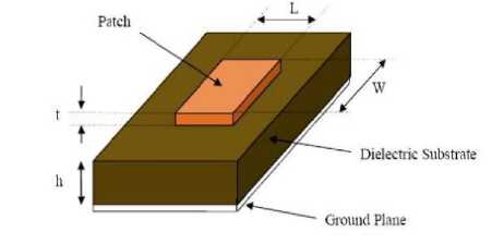
Fig. 1. Schematic Diagram of a rectangular patch antenna
As a rule of thumb, in patch designing the ht ≪ λ0 and the range should be 0.03λ0 ≤ h ≤ 0.05λ0 followed by the relative permittivity of the substrate (єr) to be within 2.2 ≤ єr ≤ 12. Most crucial role in the designing of microstrip patch antenna is the selection of resonant frequency and the substrate. The dielectric of the substrate controls the bandwidth and gain values of the antenna. Loss Tangent [7], this term refers to how much of the electromagnetic wave passing through a dielectric is absorbed or misplaced within the dielectric. Therefore, substances with low loss tangent were considered in this work. The height for the substrate materials (h) for the rectangular microstrip patch antenna is 1mm. The methods for feeding the patch antennas are microstrip line feed, coaxial feed and aperture coupled feed. In this paper, inset microstrip feed line [8] is used for feeding the rectangular microstrip patch antenna which is very efficient in term of impedance matching. We have considered Zo = 50 Ohm.
The length and width of the antenna may be determined out through the usage of the subsequent equations:
W=
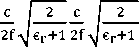
where c is speed of light, f is the frequency, єr is relative permittivity of substrate
L = Leff - L
where Leffis the effective length of the patch can be expressed as
Leff =
where єeffis the effective relative permittivity given as follows:
є = є r +1 + є r -1 (1+ 12h )- 1 2 eff W W W
and L is the length extension given as follows:
L = 0.412h
(єeff+0.3)(W+0.264)
W (єeff-0.258)( +0.8)
The corresponding length Lg and width Wg of the substrate and height of the substrate h roughly indicate the dimension (length × width × height) of the patch antenna. These values are found out from the following given equations.
Lg = L + 6h
W g = W + 6h
Based on these equations the tentative dimension of the rectangular patch antenna can be found out.
4. Proposed Rectangular Slotted Patch Antenna
As mentioned earlier, researchers have designed a rectangular slotted microstrip patch antenna that will work on dual band i.e. 28 GHz and 46 GHz using copper patch and ground plate. For better gain, the substrate is chosen as polycarbonate (loss free) with an epsilon value of 2.9 and loss tangent 0.000660 - 0.0100 [6]. The authors have used inset feed method for impedance matching where characteristic impedance is assumed to be 50Ω. Initially, the rough dimensions of the rectangular patch antenna have been calculated using the above mentioned conventional equations with 1mm thick substrate and 0.05 mm thick copper patch. Next, two rectangular slots with semicircular edges are used to achieve the dual band resonance. Manual tuning of different dimensions is done to achieve best performance of the antenna. The outline structure of the proposed antenna is given in Fig. 2.
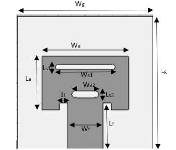
Fig. 2. Outline of the proposed slotted rectangular microstrip patch antenna
The size of the different variables i.e. dimensions and corresponding description of the proposed patch antenna are given in Table 1.
Table 1. Different dimension of the proposed patch antenna
|
Variables |
Description |
Value(mm) |
|
W g |
Width of ground |
10 |
|
L g |
Length of ground |
10 |
|
H g |
Height of ground plate |
0.05 |
|
W a |
Width of patch |
6.348 |
|
L a |
Length of patch |
4 |
|
H a |
Height of patch |
0.05 |
|
W f |
Width of feed line |
2.59 |
|
L f |
Length of feed line |
3.5 |
|
I 1 |
Width of Inset feed |
0.6 |
|
L s1 |
Length of upper rectangular slot |
0.4 |
|
W s1 |
Width of upper rectangular slot |
4 |
|
L s2 |
Length of lower rectangular slot |
0.5 |
|
W s2 |
Width of lower rectangular slot |
1.32 |
|
h |
Height of substrate |
1 |
|
R s1 |
Radius of semicircular slot at the end of the upper rectangular slot |
0.2 |
|
R s2 |
Radius of semicircular slot at the end of the lower rectangular slot |
0.25 |
5. Results and Discussion
By using the above mentioned dimensions, the patch antenna has been drawn and simulated using CST Studio. Corresponding outputs i.e. return loss, VSWR, bandwidth, current distribution, radiation pattern, directivity and impedance are also observed and discussed in details below.
-
5.1 Structure of Antenna
-
5.2 Return loss
Front and rear views of the proposed structure of dual band microstrip antenna (using CST Studio) are shown in Fig. 3 and Fig. 4 respectively.
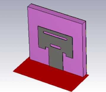
Fig. 3. Front view of proposed rectangular slotted patch antenna (using CST Studio)
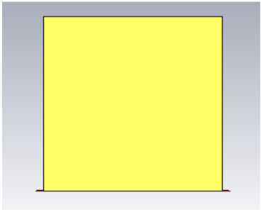
Fig. 4. Rear view of proposed rectangular slotted patch antenna (using CST Studio).
S11 measures the amount of power that is reflected from the antenna, which is also called the return loss. It should be very small at the resonance frequency. The return loss of the antenna design being proposed is shown in Fig. 5. It can be observed that the proposed patch antenna resonates at two frequencies at 28 GHz and 46GHz respectively. The return losses at these frequencies are given -45.21dB and -39.60dB respectively which are very satisfactory for the present problem of 5G antenna designs.
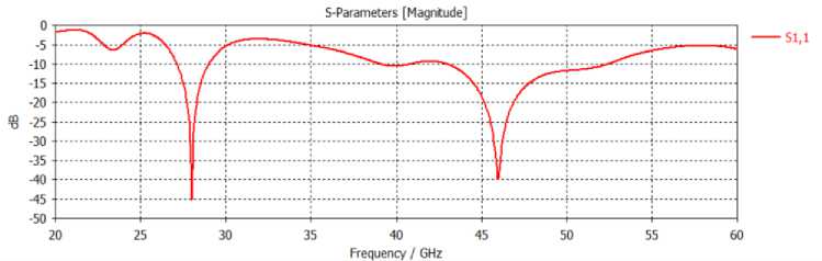
Fig. 5. S-parameter for the proposed dual band patch antenna
Table 2. Return loss for proposed dual band patch antenna at different operating frequency
|
Operating Frequency |
28 GHz |
46 GHz |
|
Return loss |
-45.21dB |
-39.60 dB |
5.3 Bandwidth
It is a very important parameter to measure the performance of an antenna. For 5G applications, the required bandwidth should be large to accommodate the high speed internet connectivity. For bandwidth calculation, we should consider the frequency range where the value of S 11 falls below -10dB. From the above figure, the upper frequency, lower frequency and operating bandwidth associated with different resonance frequencies are given in the following table.
Table 3. Different parameters for calculation of bandwidth for proposed dual band patch antenna
|
Operating Frequency |
28 GHz |
46 GHz |
|
fL (lower frequency) |
27.16 GHz |
43.00GHz |
|
fH (Higher frequency) |
29.00 GHz |
52.00 GHz |
|
Bandwidth (BW) |
1.84 GHz |
9.00 GHz |
It can be observed that bandwidth for the proposed patch antenna are 1.84 GHz and 9.00GHz at 28GHz and 46GHz respectively which are very much suitable for 5G applications.
-
5.4 VSWR
-
5.5 Z-parameters
VSWR stands for Voltage Standing Wave Ratio, which gives an idea about the power that is reflected from an antenna due to load mismatch. Ideally, the value of VSWR should be ‘1’ that indicates proper matching conditions at operating frequency. The VSWR graph at different frequencies for the proposed dual band patch antenna is shown in Fig. 6.
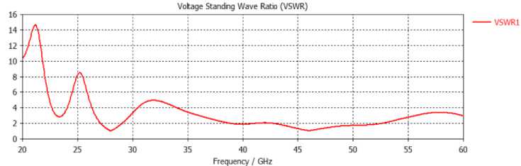
Fig. 6. VSWR graph for the proposed dual band patch antenna
The values of the VSWR at 28GHz and 46GHz resonance frequency are found as 1.011 and 1.021 respectively. From Table 4, it has been found that the value of VSWR for the proposed antenna is very satisfactory and indicates a very good matching.
Table 4. VSWR for proposed dual band patch antenna at different operating frequency
|
Operating Frequency |
28 GHz |
46 GHz |
|
VSWR |
1.011 |
1.021 |
The Z parameter or impedance is used to determine the quality factor of an antenna which can give you an insight about the attainable bandwidth. Here, we have used inset feed technique for proper matching and characteristic impedance is considered as 50Ω. Fig. 7 shows the Z parameters proposed microstrip antenna. It has been observed that the values of Z-parameter are 51.41Ω and 52.17Ω at 28GHz and 46GHz respectively (shown in Table 5) which are close to the characteristic impedance of the line.
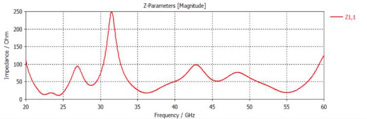
Fig. 7. Z-parameter for the proposed dual band patch antenna
Table 5. Z-parameter for proposed dual band patch antenna at different operating frequency
|
Operating Frequency |
28 GHz |
46 GHz |
|
Z-parameter |
51.41Ω |
52.17Ω |
-
5.6 Radiation Pattern
Radiation pattern of antenna gives us various information like gain or directivity, half power beam width (HPBW), major lobe, minor lobe etc. 3D-Radiation pattern for the proposed antenna at 28 GHz and 46 GHz respectively is shown in Fig.8.
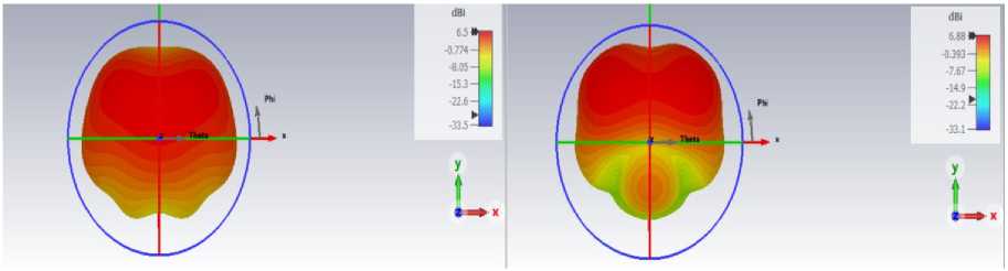
Fig. 8. 3D Radiation pattern for the proposed antenna at 28 GHz and 46 GHz respectively
The far-field 2D radiation patterns of the proposed antenna in polar graph are shown in Fig. 8 and Fig. 9 respectively. This antenna shows to be very efficient for 28 GHz operating frequency with 58.0 degree HPBW. It is very operational at 46 GHz operating frequency with 50.3 degree HPBW. Others parameters like major lobe magnitude, minor lobe magnitude, first null beam width (FNBW) are also mentioned in the following Fig. 9 and 10.
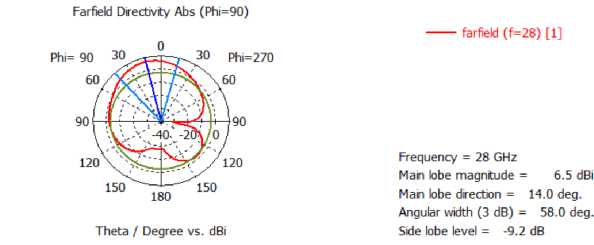
Fig. 9. Radiation pattern in 2D in polar coordinate at 28 GHz
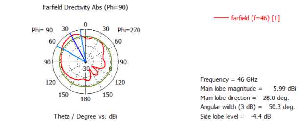
Fig. 10. Radiation pattern in 2D in polar coordinate at 46 GHz
Moreover, it has been also observed that the proposed rectangular slotted patch antenna has directivity of 6.499 dBi and 6.880 dBi at 28 GHz and 46 GHz respectively which are very satisfactory. Due to its efficiency at both frequencies, it can be implemented for dual-band applications. Following table summarizes different radiation characteristics of the proposed patch antenna.
Table 6. Radiation characteristics for proposed dual band patch antenna at different operating frequency
|
Operating Frequency |
28 GHz |
46 GHz |
|
Directivity |
6.499dBi |
6.880dBi |
|
Gain |
6.25dB |
5.84dB |
|
Mani lobe level |
6.5dBi |
5.99dBi |
|
Minor lobe level |
-9.2dBi |
-4.4dBi |
|
HPBW |
58o |
50.3o |
|
FNBW |
14o |
28o |
-
5.7 Surface Current Distribution
-
5.8 Comparative study
Fig. 11 and 12 show surface current distribution of the above proposed structure of the antenna at the operating frequency of 28 GHz and 46 GHz respectively. In this case, it is the motion of electrical phenomena on the patch floor that are creating the current densities, which are causing antenna dissipation.
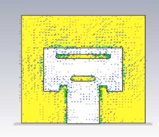
Fig. 11. Surface current distribution at operating frequency of 28 GHz
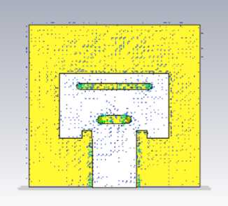
Fig. 12. Surface current distribution at operating frequency of 46 GHz
Based on the simulation results (i.e. different antenna performance parameters) using CST studio, the obtained results are also compared with six other existing works on dual band patch antenna for 5G applications. The comparison is shown in following table 7. It can be observed that the proposed antenna performed better than Hakim et al. [9] performs superior than the proposed structure as well as others. However, the proposed antenna performs better than Khattak et al. [10], Ahmad et al. [11], C.Chu et al. [12], Y. Rahayu et al. [13] and N. Ashraf et al. [14] in terms of return loss, bandwidth and VSWR also. The major drawback behind the work Y. Rahayu et al. [13] is its large size (20x20x1.57 mm3), compared to this, the work proposed in this paper is much compact and simple. It is worth to mention that all other works are on 28 GHz, 38 GHz and 28 GHz, 45 GHz respectively. The main advantage of proposed patch antenna is that it has less complicated structure which has a rectangular patch with two simple rectangular type slots.
Table 7. Comparison with similar works for 5G dual band antenna
|
Works |
Operating frequency (GHz) |
Return loss (dB) |
Bandwidth (GHz) |
Gain (dB) |
|
Hakim et al. [9] |
28 , 38 |
-54 , -51 |
5.13 , 11.6 |
8.3 , 6.38 |
|
Khattak et al. [10] |
28 , 45 |
-40 , -14 |
1.3 , 1.0 |
7.6 , 7.2 |
|
Ahmad et al. [11] |
28 , 38 |
-40 , -18 |
3.34 , 1.39 |
3.75 , 5 |
|
C. Chu et al. [12] |
28 , 38 |
-29 , -24 |
1.02 , 3.49 |
6 , 4 |
|
Y. Rahayu et al [13] |
28 , 38 |
-40.6 , -32.6 |
4.86 , 3.60 |
5.75 , 7.23 |
|
N. Ashraf et al. [14] |
28 , 38 |
-25 , -30 |
0.45 , 2.20 |
5.2 , 5.9 |
|
Proposed antenna |
28 , 46 |
-45.21 , -39.60 |
1.84 , 9 |
6.25 , 5.84 |
6. Conclusion
The design of dual band patch antenna for 5G communication is a current trend in this research area of communication. In this paper, the simple rectangular patch antenna with double slots is proposed to obtain dual operating frequency. The proposed antenna is designed and simulated using CST studio and it has been out that it operated in 28 GHz and 46 GHz which are very much suitable for 5G communications. The proposed antenna has bandwidth of 1.84 GHz and 9 GHz respectively at two above mentioned operating frequencies. The obtained return loss, VSWR, gain, HPBW etc. are found to be very satisfactory and also performed better compare to the some existing works in this area. Simple rectangular patch with two slots is the major advantage of this design. Although the antenna is not fabricated and tested physically, but we believed that it will work and become a potential candidate for efficient dual band antenna for 5G applications. Moreover, several machine learning can be employed in future for fine tuning of the performance of the proposed dual band 5G antenna.
Conflict of Interest
The authors declare that there is no conflict of interest associated with this research.
References Design of Dual Band Microstrip Patch Antenna for 5G Communication Operating at 28 GHz and 46 GHz
- R. Vickers and T. Vilmansen, "The evolution of telecommunications technology," in Proceedings of the IEEE, vol. 74, no. 9, pp. 1231-1245, Sept. 1986, doi: 10.1109/PROC.1986.13613.
- Final Acts WRC-15 World Radio communication Conference Geneva, http://handle.itu.int/11.1002/pub/80d4e1c0-en, . (Accessed on 25/10/2022).
- S. Sagiroglu and D. Sinanc, "Big data: A review," 2013 International Conference on Collaboration Technologies and Systems (CTS), 2013, pp. 42-47, doi: 10.1109/CTS.2013.6567202.
- K. -F. Lee and K. -F. Tong, "Microstrip Patch Antennas—Basic Characteristics and Some Recent Advances," in Proceedings of the IEEE, vol. 100, no. 7, pp. 2169-2180, July 2012, doi: 10.1109/JPROC.2012.2183829.
- Meena, M., and P. Kannan. "Analysis of microstrip patch antenna for four different shapes and substrates." ICTACT J. Microelectron 4.01 (2018), doi:10.21917/ijme.2018.0092.
- https://www.rfcafe.com/references/electrical/dielectric-constants-strengths.html (Accessed on 25/10/2022).
- P. H. Bolivar et al., "Measurement of the dielectric constant and loss tangent of high dielectric-constant materials at terahertz frequencies," in IEEE Transactions on Microwave Theory and Techniques, vol. 51, no. 4, pp. 1062-1066, April 2003, doi: 10.1109/TMTT.2003.809693.
- Upadhyay, Priya, and Richa Sharma. "Design and study of inset feed square microstrip patch antenna for s-band application." International Journal of Application or Innovation in Engineering & Management (IJAIEM) 2, no. 1 (2013): 256-262.
- M. L. Hakim, M. J. Uddin and M. J. Hoque, "28/38 GHz Dual-Band Microstrip Patch Antenna with DGS and Stub-Slot Configurations and Its 2×2 MIMO Antenna Design for 5G Wireless Communication," 2020 IEEE Region 10 Symposium (TENSYMP), 2020, pp. 56-59, doi: 10.1109/TENSYMP50017.2020.9230601.
- Khattak, Muhammad &Sohail, Amir & Khan, Ubaid & Ullah, Zaka&Witjaksono, Gunawan. (2019). Elliptical Slot Circular Patch Antenna Array with Dual Band Behaviour for Future 5G Mobile Communication Networks. Progress In Electromagnetics Research C. 89. 133-147. 10.2528/PIERC18101401.
- Ahmad, W. and W. T. Khan, “Small form factor dual band (28/38 GHz) PIFA antenna for 5G applications,” 2017 IEEE MTT-S International Conference on Microwaves for Intelligent Mobility (ICMIM), 21–24, IEEE, March 2017.
- C. Chu, J. Zhu, S. Liao, A. Zhu and Q. Xue, "28/38 GHz Dual-band Dual-polarized Highly Isolated Antenna for 5G Phased Array Applications," 2019 IEEE MTT-S International Wireless Symposium (IWS), Guangzhou, China, 2019, pp. 1-3.
- Y. Rahayu and M. I. Hidayat, "Design of 28/38 GHz Dual-Band Triangular-Shaped Slot Microstrip Antenna Array for 5G Applications," 2018 2nd International Conference on Telematics and Future Generation Networks (TAFGEN), Kuching, 2018, pp. 93-97.
- N. Ashraf, O. Haraz, M. A. Ashraf and S. Alshebeili, "28/38-GHz dual-band millimeter wave SIW array antenna with EBG structures for 5G applications," 2015 International Conference on Information and Communication Technology Research (ICTRC), Abu Dhabi, 2015, pp. 5-8.
- D. Saha, S. Mandal, K. Purkait, “Design of Rectangular Slotted Microstrip Patch Antenna for 5G Applications at 27GHz”, in the IEEE Proceedings of the International Conference on Intelligent Innovations in Engineering and Technology (ICIIET)-2022, [In Press].
