Design of Microwave Antenna for Hyperthermia System

Author: Minu Sethi, Geeta Nijhawan
Journal: International Journal of Wireless and Microwave Technologies(IJWMT) @ijwmt
Article in issue: 4 Vol.6, 2016.
Free access
Hyperthermia is a thermal therapy for cancer treatment in which body temperature is exposed to elevated temperature of 40-42oC. Microwave ablation has a potential to be sensitive to changes in the dielectric tissue parameters which results in damaging abnormal tissues. In order to produce heat in the focused area microwave signals are adjusted in time, frequency and strength. The commonly used frequencies in microwave imaging systems are 415MHZ and 2.45GHZ which are transmitted from the antennas enclosing the relevant body part. This paper presents a highly efficient E-Shape micro strip patch microwave antenna operated at 2.45 GHz which can be used in various applicators for hyperthermia treatment system. The simulation is done on IE3D simulator. The results are compared at two feeding points 1 and 2 for the frequency 2.45GHZ. It gives return loss of -19.3dB, bandwidth of 6.2dB and the antenna efficiency of 92% for feeding point 1 which proves to be highly effective in communication.
Hyperthermia, Microwave ablation, E-shape, Micro strip patch antenna, return loss, radiation pattern
Short address: https://sciup.org/15012944
IDR: 15012944
Text of the scientific article Design of Microwave Antenna for Hyperthermia System
Published Online July 2016 in MECS DOI: 10.5815/ijwmt.2016.04.04
-
I. Introduction
-
2. Design Equations
Hyperthermia is a cancer treatment thermal process in which tumor loaded tissues are exposed to heat up to 42-45oC. The biological response of hyperthermia is protein damage which involve both cellular and host related factors [1]. It results in direct killing of raised temperature cancerous cells, increased metabolic activity, increased cell oxygenation, stimulation of immune system and an improvement of cells to drug intake [2]. Microwave hyperthermia is one of the promising techniques that has been used in the treatment of patients suffering from cancer. Depending upon the size and location of tumor one or more microwave antennas are
* Corresponding author.
used [3]. Based on the power absorption microwave antenna applicators raise the temperature of tumor and has a potential to create longer and effective thermal lesion at a greater depth. One of the main advantage is application time which is shorter for microwave frequencies [4]. The federal communication commition (FCC) or International telecommunication union (ITU) permit several unrestricted frequency bands for industrial, scientific and medical uses in several regions including those most commonly used frequencies for microwave ablation are 915MHZ and 2.45GHZ [5]. For the treatment of cancer patients having superficial tumors waveguide and intracavity applicators have been used at frequency 2450MHZ. The penetration depth of EM energy approaches the tumorous part with low irradiation in the vicinity of hyperthermia apparatus and good impedance matching is achieved by microwave thermotherapy which can be effectively used in local external hyperthermia treatment of cancer [6][7].
An antenna suffer much in terms of efficiency and matching, so there is a need for highly efficient antenna which provide more directivity and less return loss. Low loss materials are used in designing many antennas so that more of the power that is not reflected is radiated [8]. Micro strip patch antenna is a narrowband wide beam antenna which is mostly used at microwave frequencies because the size of the antenna is directly tied to the wavelength at resonant frequency [9]. A thicker substrate will increase the radiation power, reduce conductor loss and improve bandwidth [10]. Micro strip line feeding has been used in which a conducting strip is connected directly to the edge of micro strip patch [11]. The position of the feeding also changes the results [12].
In this paper E shaped micro strip patch antenna is designed for microwave frequency 2.45GHZ by using various design equations. The results have been compared for two different feed positions. Simulations are done on IE3D software which uses a method of moment (MOM) numerical technique [13].The rest of the paper is organized as follows: Section II gives the design equations used for E-shape micro strip patch microwave antenna. Description of proposed microwave antenna is being dealt in detail in Section III. Section IV provide results and discussions and finally in Section V Conclusions of the proposed work are drawn.
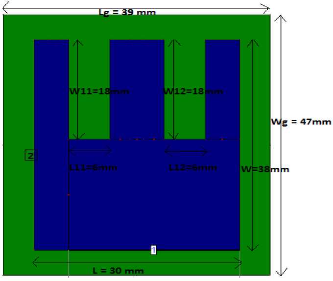
The design of micro strip patch antenna is E-shape. To simplify the analysis and performance prediction rectangular patch element is chosen. The main characteristics parameters of antenna are length (L), Width (W), Thickness (h) ,two cut slots of dimensions L11,W11 and L12,W12 are shown in fig1.Theorical analysis and calculations of dimensions can be calculated by using equations (1 to 7) of transmission line method [14-16] which are shown in Table1.
Calculation of Width : The first step of antenna design is calculate the width of micro strip patch antenna which is given by
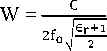
Calculation of Effective Dielectric Constant : To calculate the actual length of micro strip antenna first calculate the effective dielectric constant which is given by the formula
∈ = ∈ -^ + ∈ ■ ( √ )
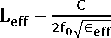
Calculation of Effective Length ( Leff ) : The effective length of the microwave antenna can be calculated by using the formula
Calculation of the length extension (AL) : To find the actual length first find the length extension by using the formula
∆ = 0.412 ( ∈ ․ ) ( . )
( ∈ . ) ( . )
Calculation of actual length (L) : The actual length of the microwave patch antenna is calculated by using equation
L = - 2∆
For practical consideration there is a need for finite ground plane which can be calculated if size of ground plane is six times greater than thickness of substrate.
L = L + 6h
W = W + 6h
3. Description of Proposed Microwave antenna
The design of proposed microwave antenna is rectangular E-Shape as shown in Fig.1 in which two slots are cut. L and W are the length and width of antenna in which two rectangular slots having length L11, L12 and Width W11, W12 are cut. As there is a need for finite ground plane, the ground parameters are also taken rectangular having length Lg and Width Wg. The proposed antenna dimensions are calculated by using design equations which are shown in Table 1. The antenna is designed for frequency 2.45GHZ. For the improvement of radiation power, bandwidth and to reduce the conductor losses thicker substrate is used. The material used for dielectric is FR4 having dielectric constant 4.3 and height of the substrate is 1.5 mm. Micro strip line feeding is used at two points 1, 2 and the results shows drastic change when the feeding position is change from position 1 to position 2.
Table 1. Proposed Antenna Dimensions
|
S.NO |
Patch Length L(mm) |
Patch Width W(mm) |
Ground Length (mm) |
Ground Width (mm) |
Slot Cut Length L11(mm) |
Slot Cut Length L12(mm) |
Slot Cut Width W11(mm) |
Slot Cut Width W12(mm) |
|
1. |
30 |
38 |
39 |
47 |
6 |
6 |
18 |
18 |
-
4. Results and Discussions
The return loss or reflection loss measured the effectiveness of power delivery from the transmission line to the antenna. Simulated data of IE3D is used to plot graphs which gives return loss of -19.3 dB for A1 at feeding position 1 which when compared for A2 at feeding position 2 gives return loss of -4 dB that shows drastic change as shown in fig 2. To provide more directivity antenna with high efficiency is needed. The proposed antenna gives efficiency of 92% as shown in fig.3. The range of usable frequency within which performance of antenna with respect to some characteristics conforms to a specified standards gives bandwidth of 6.2 dB as shown in fig 4 which proves to highly effective. The antenna has an acceptable performance with VSWR ≤ 2. Fig.5. shows the voltage standing wave ratio graph which value of 0 at 2.45GHZ.The azimuth pattern gain display and 3D radiation pattern shows that antenna radiates its energy equally in all directions. Fig. 6 and Fig. 7 shows that the impedance matching of proposed antenna exhibit good matching at 50Ω using line feeding. The results gives a design of highly effective E-shape micro strip patch antenna which can be used in various applications for hyperthermia system.
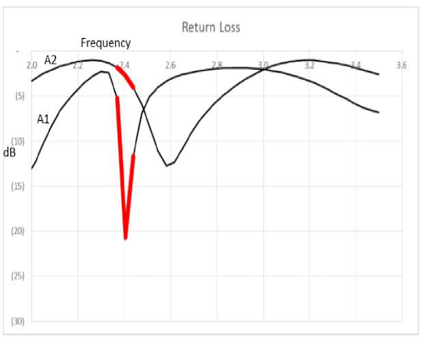
Fig.2.Comparison of return loss for microstrip line feeding position 1 and 2
Efficiency Vs. Frequency
Peicentege ГО
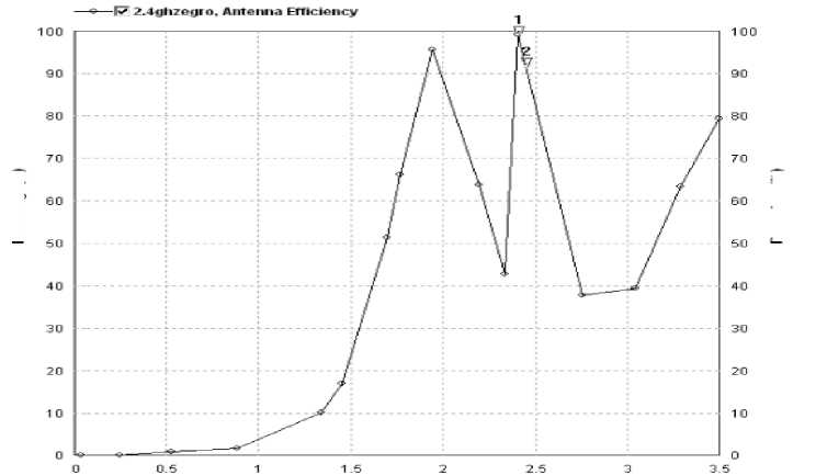
(tiiBeiiaii»d
Frequency (GHz*
Fig.3.Efficiency verses Frequency Graph
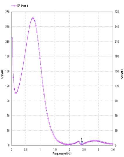
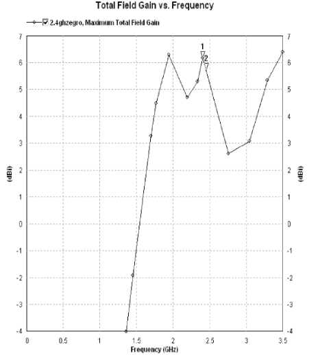
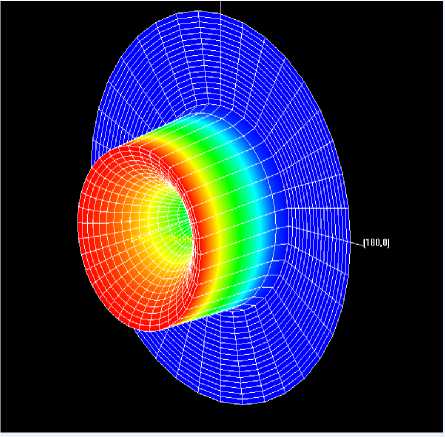
Fig.6.3D Radiation pattern for antenna
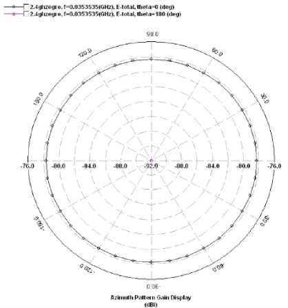
Fig.7.Azimuth pattern Gain display
-
5. Conclusions
In this work effort has been made to design highly efficient rectangular E-shape micro strip patch antenna for microwave frequency of 2.45GHZ used in hyperthermia system for cancer treatment. FR-4 substrate of thickness 1.5mm and dielectric constant of 4.3 is used in this application. To provide a planer structure, a technique of micro strip line feeding has been used in which a conducting strip is connected directly to the edge of micro strip patch. The arrangement also has the advantage that feed can be etched on the same substrate.
Better results have been observed by applying direct feeding to the lower edge of the patch. Simulations of Eshape microwave antenna for hyperthermia system are done on IE3D software which uses a method of moment (MOM) numerical technique which has been effectively applied to electromagnetic problems related to human body.
References Design of Microwave Antenna for Hyperthermia System
- Riadh W. Y. Habash, Rajeev Bansal et al. Thermal Therapy, Part 2: Hyperthermia Techniques. Critical Reviews TM in Biomedical Engineering. 34(6):491–542 (2006).
- Max J. Ammann, Sergio Curto. Compact Patch Antenna for Electromagnetic Interaction with Human Tissue at 434 MHz IEEE Transaction on Antennas and propagation. Vol. 57, No. 9, September 2009.
- Minu sethi and S.K.Chakarwarti. Hyperthermia Techniques for cancer treatment: A Review. International Journal of PharmTech Research, Int.J. PharmTech Res. 2015, 8(6), pp. 292-299.
- J. Trujillo, L. Leija and A. Vera. Design and Preliminary Evaluation of a Superficial Applicator for Hyperthermia with a New Coaxially Fed Antenna: Theoretical Models. Nano medicine Journal, Vol 3, pp. 2-9, 2011.
- A. Rosen, M. A. Stuchly, and A. Van Vorst. Applications of RF/microwaves in medicine. IEEE Trans. Microwave. Theory Tech., Vol. 50, pp. 963–974, Mar. 2002.
- Vrba, J. Franconi, C. Lapeš, M. Theoretical Limits for the Penetration Depth of Intracavitary Applicator. Int. J. of Hyperthermia, 1996, No.6.pp.737–742.
- Vrba, J. Lapeš, M. Oppl. Technical aspects of microwave thermotherapy. Bio electrochemistry and Bioenergetics. Vol. 48 (1999). pp. 305 – 309.
- http://www.antenna-theory.com/definitions/sparameters.php (2011-09-18)
- Micro strip Antennas. IEEE International Symposium on Antennas and Propagation, Williamsburg Virginia, 1972 pp. 177-180.
- Aqeel Ahmad Qureshi, Muhammad Usman Afzal, et al. Performance analysis of FR-4 substrate for high frequency micro strip antennas. IEEE Microwave Conference Proceedings (CJMW), 2011 China-Japan Joint IEEE Microwave Conference Proceedings (CJMW), 2011 China-Japan Joint.
- Daniel C. Nascimento, Ricardo Schildberg and J. C. da S. Lacava. Design of Low-cost Microstrip Antennas for Glonass Applications. Progress in Electromagnetics Research Symposium, Cambridge, USA, July 2–6, 2008
- Patil V. P. Enhancement 0f bandwidth of rectangular patch antenna using two square slots techniques. International Journal of Engineering Sciences & Emerging Technologies, Oct. 2012. ISSN: 2231 – 6604. Volume 3, Issue 2, pp.: 1-12 ©IJESET
- M. M. Ney, Method of Moments applied as Applied to Electromagnetic Problems, IEEE Trans. Microwave Theory Tech., Vol. 33, pp. 972-980, October 1-985.
- Balanis C. A. Antenna Theory, Analysis and Design. 3rd ed. Hoboken, NJ: Wiley, 2005.
- J. R. James and P. S. Hall. Handbook of micro strip antennas. Peter Peregrinus, London, UK, 1985.
- D. M. Pozar, and D. H. Schaubert. Microstrip Antennas, the Analysis and Design of Microstrip Antennas and Arrays. IEEE Press, New York, USA, 1995.
- Bird, Trevor S. Definition and Misuse of Return Loss. IEEE Antennas and Propagation Society (2009), Volume 51, Issue 2, page(s) 166-167.
- Shagun Maheshwaria, Priyanka Jaina, Archana Agarwal. CPW-fed Wideband Antenna with U-shaped Ground Plane. I.J. Wireless and Microwave Technologies, 2014, 5, 25-31.
- W. Xia, K. Saito, M. Takahashi, and K. Ito. Performances of an implanted cavity slot antenna embedded in the human arm. IEEE Trans.Antennas Propag. vol. 57, pp. 894–899, Apr. 2009.
- F. Jouvie, J.-C. Bolomey, and G. Gaboriaud. Discussion of Capabilities of Microwave Phased arrays for Hyperthermia Treatment of Neck Tumors. IEEE Transactions on Microwave Theory and Techniques, vol. 34, pp. 495-501, 1986.
- Cheung AY. Microwave hyperthermia for cancer therapy. IEE Proc. 1987. 134:493–522.
- Magin RL, Peterson AF. Noninvasive microwave phased arrays for local hyperthermia: a review. Int J Hyperthermia. 1989; 5: 429–50.
- Fessenden P, Hand JW. Hyperthermia therapy physics. In: Smith AR, Editor. Medical radiology: radiation therapy physics. Berlin: Springer-Verlag. pp. 315–63, 1995.
- Nguyen, P. T., A. M. Abbosh, and S. Crozier, "Realistic simulation environment to test microwave Hyperthermia treatment of breast cancer. IEEE International Symposium on Antennas and Propagation and USNC-URSI Radio Science Meeting, 1188–1189, 2014.
- Trefn´a, H. D., J. Vrba, and M. Persson, Time-reversal focusing in microwave hyperthermia for deep-seated tumors. Physics in Medicine and Biology, Vol. 55, No. 8, 2167–2185, 2010.
- Wang, G., Y. Gong, and H. J.Wang. Schemes of microwave hyperthermia by using flat left-handed material lenses. Microwave and Optical Technology Letters, Vol. 51, No. 7, 1738–1743, 2009.
