Design of Microwave Pyramidal Absorber for Semi Anechoic Chamber in 1 GHz~20 GHz range

Author: Zahid Ali, Badar Muneer, Bhawani Shankar Chowdhry, Shehroz Jehangir, Ghulam Hyder
Journal: International Journal of Wireless and Microwave Technologies @ijwmt
Article in issue: 2 Vol.10, 2020.
Free access
In this paper, the design and development of wideband microwave pyramidal absorbers for semi anechoic chambers has been presented. This work is carried out with the goal of simulating and fabricating the microwave absorber using conventional and newest material such as polyurethane to save the budget cost with security and reliability. The simulation of absorber is performed via Computer Simulation Technology (CST) for the microwave frequencies 1 GHz to 20 GHz. The outcomes of simulation proved good absorbing efficiency and better RCS reduction compared to traditional microwave absorber. The reflection level is less than -30 to -10 dB over the desired frequency range of 1 GHz ~ 20 GHz.
Microwave Absorbers, Electromagnetic (EM) waves, Dielectric permittivity, Polyurethane and Radar Cross Section (RCS)
Short address: https://sciup.org/15017630
IDR: 15017630 | DOI: 10.5815/ijwmt.2020.02.03
Text of the scientific article Design of Microwave Pyramidal Absorber for Semi Anechoic Chamber in 1 GHz~20 GHz range
The materials of microwave absorber used in the anechoic chamber must be capable to minimized microwave frequency reflections. Mostly the Semi anechoic chamber industrialists[3] recommend a standardized structure in the shape of pyramid. Although different other types can be used as wedge absorbers, ferrite tiles and Hybrid absorbers[4].
Traditionally, various materials are used to manufacture the microwave absorbers, few of them are ferrite tiles, polyethylene, polystyrene, polyurethane and numerous others contain from agriculture wastage[5]. The correct specifications of design for appropriate absorber can only be established on the basis of material dielectric constant (ε), loss tangent (δ) in the analysis of microwave absorber[6]. Absorber is primarily used to mitigate forward scattering, as well as backward scattering, creating an ideal environment inside all the positions of Semi Anechoic Chamber[7]. Absorber are found in various thicknesses range which allows the chamber designers to select the best for particular range of frequencies and incidence angles[8].
Microwave absorbers are normally black as created then colored with blue latex paint to enhance the reflection of lights. The paint will decrease the absorber’s reflectivity up to 5 dB at 95 GHz, so that the peaks are normally kept unpainted in anechoic chambers wherever millimeter (mm) calculations need to be done[9]. Moreover it is also perceived that if the peaks remain unpainted, it reduces the breakage of peaks due to wear and tear found in regular operations of Anechoic Chamber. Absorber Foams are not so durable needs high cost of maintenance.
The simulation of absorber can be performed in commercially available FEM simulation tools by specifying three significant parameters, permittivity, permeability and low reflection loss [10].
Material’s Permittivity is calculated as a result of product may generate electrical field within a medium is represented as.
-
"£ * = £' - jE" (1)
With electric loss tangent
tanSe =
B E
Constant value of permittivity in free space.
eq = 8.854 x10⁻¹² farads/meter
Material’s permeability is the measurement of product may generate magnetic field within a medium is represented as.
Ц * = ц'-;ц" (2)
With magnetic loss tangent
tan 5т = у m ^,
Constant value of permeability in free space ц0 = 4я x 10 7 henrys/meter
RL^lOlog^ [Pr/pi ]
Where,
Pr is plane wave reflected power density Pi is plane wave incident power density
-
2. Design of Microwave Absorber
3. Monostatic RCS Method
Microwave absorber was designed by Computer Simulation Tool (CST) and is developed on the standard of EMC PIONEER (SA-150). The absorber design is configured with three different materials: using Polyethylene, Polystyrene and Polyurethane. It has two different parts to merge into a single shape of pyramid. The upper triangular part of pyramid truncated at the peak with the height of 150mm and the rectangular part which is base of the pyramid having the height of 30mm.
The triangular side of the pyramidal absorber has a length (56mm) x width (56mm) x height (120 mm). The rectangular part of the pyramidal absorber which is the base has a length (56mm) x width (56mm) x height (30 mm). However the complete measurement of the pyramidal shape microwave absorber is 56mm x 56mm x 150mm as shown in Figure 1.
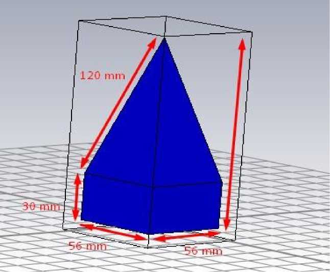
Fig. 1. Measurement of Microwave Absorber
Monostatic Radar Cross Section (RCS) is known as the field that can seamlessly detect the presence of object when transmit and receive the electromagnetic waves from its single radar source to destination. This approach is specifically used to describe the reflection loss of microwave pyramidal shape absorber.
The Equation of RCS is shown by the ratio of backscattered power density to the radar receiver and to the incident power density on target[12].
RCS (a) = 4ttR2 -
V 7 Pi
Where, т = Radar Cross Section [m2 or dBsm]
R = distance from target [m]
Pr = Backscattered Power density [Watt/ m2]
Pi = Incident Power density [Watt/ m2]
Wave equation drive from Maxwell’s equations:
V2E -це^=0
st2
Solution of plane wave equation
E (z, t) = E0 r:V-iv
Polarization of incident plane waves have angles 9 = 0, ф = 0 degrees and the direction of propagation is 90 degree towards the absorber.
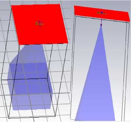
Fig. 2 Direction of Plane waves
-
4. Results and Discussion
-
4.1. Radar Cross Section of Polyethylene
The CST simulated outcomes in Fig. 3 signifies the reflection loss of microwave absorber design in Fig. 1 with dielectric permittivity (ε) = 2.25 Polyethylene. Form the graph the excellent reflection loss is -38.725dBsm at low frequency 1.0162GHz. It is also express a good absorbing rate -12.089dBsm at high frequencies from 17.999GHz. It can be seen from the figure below that the RSC reduction is better than 10 dBsm for the whole frequency range from 1GHz to 20 GHz.
-
4.2. Radar Cross Section of Polystyrene
The results in Fig. 4 presents the reflection loss Microwave pyramidal shape absorber with dielectric permittivity (ε) = 2.6 Polystyrene. Form the graph it is identified the good performance -37.06dBsm at frequency 1.0199GHz which is quite similar to that Polyethylene but bad absorption found -8.7964dBsm at high frequency 17 GHz less than -10dBsm which could not fulfill the criteria of best microwave absorber.
-
4.3. Radar Cross Section of Polyurethane
The results in Fig. 5 presents the reflection loss of microwave absorber design in Fig. 1 with dielectric permittivity (ε) = 3.5 of Polyurethane. From the graph, it is identified the excellent reflection loss -34.25 dBsm at low frequency 6.0081GHz as well as good reflection loss at high frequencies below -10dBsm.
The CST simulation is performed to identify the reflection of microwave pyramidal shape absorber by using Monostatic RCS technique as shown in Fig. 2. There were three different materials used to select the best microwave absorber for present application with high reflection loss for Semi Anechoic Chamber between the desired Frequency Range 1 GHz to 20 GHz.
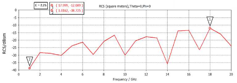
Fig. 3. RCS of Polyethylene Microwave Pyramidal Absorber
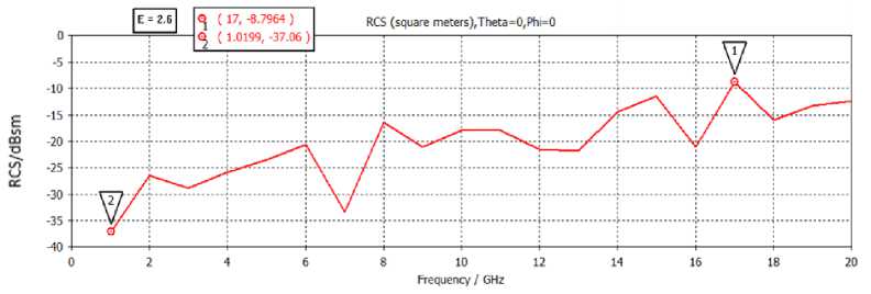
Fig. 4. RCS of Polystyrene Microwave Pyramidal Absorber
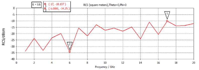
Fig. 5. RCS of Polyurethane Microwave Pyramidal Absorber
This means that Polyethylene and Polyurethane have better reflection loss as compared to polystyrene. The result shows good absorbing performance to the desired frequency range especially at high frequency using both materials. Since Polyurethane provides good insulation, absorption, durability and safety including fire retardant capabilities with similar absorption rate compare to conventional materials therefore Polyurethane is a best choice to develop microwave absorber for Semi-Anechoic-Chamber.
-
5. Conclusion
In this research paper, various designed are perceived to identify the Radar Cross Section of a microwave absorber. Some different absorbing materials considered with their dielectric constant values. The simulated outcome shows the reflection loss better than 10 dBsm over the desired frequency range (1GHz to 20GHz), specifically at high frequencies. The Polyurethane material is so reliable, safe and secure with fire retardant capability, provides good insulation and absorption rate comparing to any other substrate. Polyurethane foam is a best material choice of Microwave Absorber for Semi Anechoic Chamber in this frequency range.
Acknowledgements
This work was fully funded by HEC Pakistan under National Research Program for Universities (NRPU#6876) and would like to thanks the supervision of Dr. Badar Muneer and Dr. Bhawani Shankar Chowdhry for their valuable review and contribution to publish this paper.
References Design of Microwave Pyramidal Absorber for Semi Anechoic Chamber in 1 GHz~20 GHz range
- M. Pospisilik, M. Adamek, P. Neumann, and S. Kovar, “Observation of semi anechoic room influence on high frequency antenna measurements,” J. Phys. Conf. Ser., vol. 1065, no. 5, pp. 0–4, 2018.
- H. Mustapha, K. H. Ismail, T. J. Daim, and S. F. Jamil, “A Review of Shielding Performance for Anechoic Chamber,” Appl. Mech. Mater., vol. 793, pp. 600–604, 2015.
- Z. Xiong, “Insights into EMC Chamber Design : How to achieve an optimized chamber for accurate EMC Measurements EMC Compliance Testing,” 2017.
- TDK, “Radio Wave Absorbers For anechoic chambers,” TDK datasheet, no. September, 2013.
- F. Malek, H. Nornikman, and O. Nadiah, “Pyramidal Microwave Absorber Design from Waste Material using Rice Husk and Rubber Tire Dust,” J. Telecommun. Electron. Comput. Eng., vol. 4, no. 1, pp. 23–30, 2012.
- S. I. Orakwue and I. P. Onu, “Pyramidal Microwave Absorber Design for Anechoic Chamber in the Microwave Frequency Range of 1GHz to 10GHz,” Eur. J. Eng. Res. Sci., vol. 4, no. 10, pp. 1–3, 2019.
- V. S. Reddy and P. Kralicek, “Modeling of semi-anechoic chamber for use in automotive EMC simulations,” IEEE MTT-S Int. Microw. RF Conf. 2015, IMaRC 2015, pp. 77–80, 2016.
- H. Nornikman, P. Soh, and A. Azremi, “Performance of Different Polygonal Microwave Absorber Designs Using Novel Material,” Int. Symp. Antennas Propag., no. Isap, pp. 1151–1154, 2009.
- “Top 10 Anechoic Absorber Considerations for RF and Microwave Applications.”
- Arthur von Hippel, “Theory and Applications of RF/Microwave Absorbers,” Emerson Cuming Microw. Prod. Inc 28, pp. 1–19, 2012.
- N. Hassan et al., “Measurement of pyramidal microwave absorbers using RCS methods,” 2010 Int. Conf. Intell. Adv. Syst. ICIAS 2010, pp. 6–10, 2010.
- T. Maamria and H. Kimouche, “Investigation of monostatic RCS measurement for simple and complex shapes at 9.4 GHz,” 2015 4th Int. Conf. Electr. Eng. ICEE 2015, no. December, 2016.
