Design of the fastening assembly of the guys on the power spokes reflector

Author: Kolga V.V., Lykum A.I., Marchuk M.E., Filipson G.U.
Journal: Siberian Aerospace Journal @vestnik-sibsau-en
Section: Aviation and spacecraft engineering
Article in issue: 3 vol.23, 2022.
Free access
Currently, global communication systems are developing towards mastering high frequency bands for organizing high-speed information transmission channels, which requires large-sized antenna systems with reflectors up to 50 meters. Most of the technical solutions used for assembling large-sized reflectors are based on technological volumetric templates that geometrically completely imitate the necessary reflective surface of the reflector. The mass of such templates increases in cubic dependence on the increase in the diameter of the reflector, which is why it becomes more and more laborious to use them when assembling large-sized antennas due to the increase in the dimensions and weight of the templates. The purpose of the study is to design the attachment point for guy wires on the power spoke of the re-flector for a "templateless" assembly. The spoke is a composite isogrid structure on which arms are fixed for attaching power units. The fastening unit is an assembly unit consisting of a bracket and clips and al-lows you to precisely adjust the necessary pull tension force to fix the cord in the working position without the use of one-piece fastening methods. The analytical approach and finite element analysis were adopted as research methods. Using an ana-lytical calculation, the maximum tensile force of the guys in the designed unit was determined, thereby set-ting the maximum load for its operation. The coefficient of friction between the cord and the clamp in each individual case is determined experimentally. After simplifying the design and construction scheme of the bracket, the analytical calculation was carried out for a three-dimensional rod frame. To confirm the results of the calculation, a finite element model of the bracket was built and its static analysis was carried out. For the developed model of the bracket, the maximum stresses were determined and their comparative analysis was carried out with the results obtained analytically. With the help of solid modeling, the mass and overall characteristics of the braces fastening unit are determined. The limiting ranges of tension forces and the materials used in the knot, as well as its strength characteristics, were determined. This unit can be used in the "templateless" method of assembling a reflector for a wide range of large antennas, it has high manufacturability and versatility.
Attachment unit, antenna, guy ropes, cord, large-sized reflector
Short address: https://sciup.org/148329641
IDR: 148329641 | UDC: 629.7.062 | DOI: 10.31772/2712-8970-2022-23-3-451-460
Text of the scientific article Design of the fastening assembly of the guys on the power spokes reflector
ВведениеIntroduction
Currently, global communication systems are developing towards mastering high frequency bands for organizing high-speed information transmission channels. This requires antenna systems with reflector apertures of 10-50 m.
Large-size reflectors are a part of an antenna complex, responsible for reflection and amplification of a wide spectrum signal from a radiating installation [1-8]. Problems of assembly of large-sized reflectors remain relevant until now [9]. Most of the used technical solutions are based on technological volumetric templates, geometrically completely imitating the required reflecting surface of the reflector. The weight of such templates increases in cubic dependence on the increase in the diameter of the reflector, due to which their use in the assembly of large-sized antennas becomes more and more laborious because of the increase in their size and weight.
An example of such a technological solution is the method described in [10].
Analysis of existing methods of manufacturing a large-sized reflector
To manufacture a large-size reflector of a spacecraft, a metallized knitted mesh is stretched, cut into fragments, stitched along radial segments to obtain the required shape, after which the cut elements of the mesh are fixed on the power frame. Further, forming of reference marks on the working surface of the mesh is carried out taking into account the allowances in the form of tapes. Finished fragments are folded with overlapping allowances, sewed together and placed on a volumetric template of the desired shape by stretching the mesh with the required working force and smoothing out surface irregularities on the template. After obtaining the desired shape and size of the working surface the mesh is fixed with brackets, having previously placed it on the template and adjusted using tangent cords to the desired shape of the surface.
Based on the claims of the invention, the following disadvantages can be identified: labor-intensive assembly process; excessive mass component of the volumetric template, which increases in cubic dependence on the diameter of the reflector. This method of manufacturing involves the manufacture of individual cords (cut to length) and the initial assembly without taking into account the elastic properties of the cords. Because of this, it is necessary to create a system of specified tensioning forces at each stage of assembly, forming a static indeterminacy of forces in the units [10; 11].
To solve this problem in JSC «Reshetnev Information Satellite Systems» (JSC «ISS») a technical solution of «templateless» assembly of the reflector was developed, allowing to assemble the reflector with the help of weight-loss systems [12; 13]. The solution considered above lacks the necessary technical elements of detail that are necessary for its implementation, which is characteristic of patents. In particular, it requires the development of an attachment and fastening unit of a guy rope, which meets the following requirements: possibility of multiple fixation of a cord; convenient attachment to a power spoke; the ability to accurately adjust length of the cord along the OZ axis; minimization of mass-size characteristics.
Design of the guy ropes fastening unit
To implement this solution [12], we proposed the design of the attachment unit, which meets the above requirements. Let's consider a large-sized antenna reflector developed by JSC «ISS» as a basic unit [12].
During the design process, it was decided to use a clamping scheme similar to hinged clips (Fig. 1).
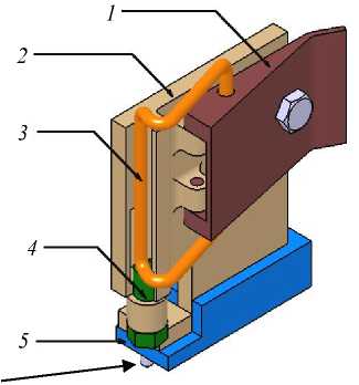
Рис. 1. Общий вид узла крепления:
1 – язычок; 2 – база; 3 – скоба; 4 – регулировочный болт;
5 – кронштейн для закрепления узла в общем виде; 6 – крепежный болт
-
Fig. 1. A general view of the fastening unit:
1 – tongue; 2 – base; 3 – bracket; 4 – adjusting bolt;
5 – arm for fixing the unit in general; 6 – mounting bolt
Such a scheme is simple to make and allows you to create sufficient force on the bracket, firmly fixing the cord, while not requiring a significant application of force due to the rule of the lever. An important point for securing the cord is the large contact area of the clamp with the cord, allowing you to eliminate the loss of strength of the cord during tensioning due to possible fracture (Fig. 1).
The tongue ( 1 ) can be secured with a bolt ( 4 ) to secure its position.
Fig. 2 shows the elements that ensure precise adjustment of the required cord length. These are the adjusting hollow bolt ( 4 ) and the notch for the cord adjustment loop in the base ( 2 ), which can be used to provide a spare length for adjustment.
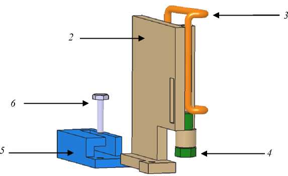
Рис. 2. Узел в снятом положении:
1 – язычок (не виден на этом рисунке); 2 – база; 3 – скоба; 4 – регулировочный болт;
5 – кронштейн для закрепления узла в общем виде; 6 – крепежный болт
-
Fig. 2. The unit in the removed position:
1 – tongue (not visible in this figure); 2 – base, 3 – bracket; 4 – adjusting bolt;
5 – arm for fixing the unit in general form; 6 – mounting bolt
The developed attachment unit provides the possibility of removing it from the support arm to install the tensioning cord on it (Fig. 2). The axis of the mounting bolt ( 6 ) is located as close as possible to the cord axis to minimize the torque from the tensioning forces and possible base rotation. At the same time, it is still possible to unscrew both mounting bolts ( 6 ) and the adjusting bolt ( 4 ) easily.
AMg6 was the material for the base (2), tongue (1), Steel 45 - for the bolts. For the bracket (3) the material selection will be made on the basis of strength calculations. Approximate calculation allowed to estimate the mass of the unit equal to 0.018 kg.
Analytical calculation of the cord tensioning force in the guy rope attachment unit
In order to ensure reliable fastening of the tensioning cord in the designed unit, it is necessary to determine the magnitude and direction of the forces in the unit. On the basis of the calculated friction force inside the working surface of the unit, it is necessary to estimate the clamping force. The required force on the force spokes guy ropes depends on the material and mechanical characteristics of the cord (friction coefficient, elastic modulus, yield strength, etc.) [14].
The force application diagram is shown in Fig. 3.
Based on this figure, the friction force is трения тяги ;
трения
= k • N ,
where N is the reaction force of the cord to the force exerted by the clamp; is the coefficient of fric- tion.
Assuming the deformations are elastic, the clamping force is
F = -N;
зажима ;
F зажима
F тяги
k
The coefficient of friction between the cord
and the base is unique in each individual case and is often determined experimentally. As you can see from the formula above, the clamp holds the guy rope due to a pulling force that is less than the clamping force. Reducing the difference between the two can be accomplished by machining the bracket and the groove where the thread will be held, thereby increasing the coefficient of friction.
In this case, we can determine the maximum force F , which can be applied to the bracket ( 3 ), by analytical calculation, thereby determining the maximum load for the operation of the designed unit.
Simplifying the design and constructive
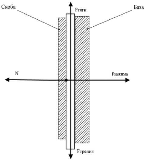
Рис. 3. Распределение сил в канавке зажима
Fig. 3. Distribution of forces in the clamping groove
scheme of the bracket, we get a spatial frame, shown in Fig. 4.
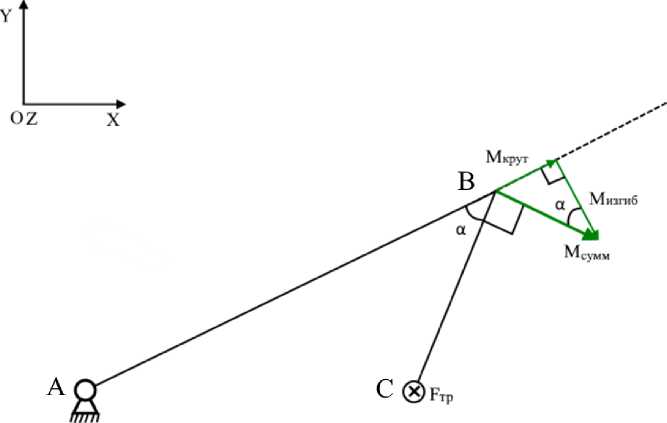
Рис. 4. Расчетно-конструктивная схема скобы
-
Fig. 4. The bracket in a simplified form
Now it is necessary to find the maximum value of force F тяги , based on the yield strength of the bracket material. According to the maximum-shear theory of failure, we write down the formula for equivalent stress and equate it to the yield strength of the material
^ экв = 4 Т А + ^ А^ ;
where о А is the normal stress at point A; т А is the tangential stress at the same point. We describe these quantities further
° A —
M A изгиб
w я
изгиб
;
M a изгиб = F яи • AB + F я. • CB • cos a
W я = изгиб
n- d3
32 ;
M л
A круч
Tj — ;
A круч
M A круч — М круч — F тяги • CB • sin « ;
= n d ■ круч 16 ;
where M is the maximum bending moment at point A; M is the bending moment at point
B; M is the maximum torsional moment at point A; W is the bending resistance moment;
W is the torsional resistance moment.
Исходя из выведенных величин, запишем выражение эквивалентного напряжения
Based on the derived values, the expression for the equivalent stress can be written as
° экв
4 ( ^ тяги • CB • sin a- 16 1 J ( ^ тяги • AB + ^ тяги • CB • cos a ) • 32
4 1 I + I
\ < П d J < П d
Hence, we can express the maximum pulling force at the unit F , since we know all the characteristics of the bracket
F тяги
Я^ d 3 • ° экв
32^2 • BC • AB • cos a + AB 2 + BC 2
By specifying the diameter of the bracket and the type of material, we calculate the dimensions of the bracket and determine the maximum allowable forces for the designed unit.
The analysis of calculation results for different diameters of the bracket d as applied to alloys AMg6, BT14 and BT16, which are quite often used in the rocket and space technology, is presented in the table.
Input data and analytical results
|
AMg6 |
VT 14 |
VT16 |
|||||||
|
d1, m |
d2, m |
d3, m |
d1, m |
d2, m |
d3, m |
d1, m |
d2, m |
d3, m |
|
|
0,0022 |
0,002 |
0,0018 |
0,0022 |
0,002 |
0,0018 |
0,0022 |
0,002 |
0,0018 |
|
|
σв, Pa |
305000000 |
850000000 |
1030000000 |
||||||
|
AB, m |
0,021 |
||||||||
|
CB, m |
0,007 |
||||||||
|
sin a |
0,78 |
||||||||
|
cos a |
0,62 |
||||||||
|
F N тяги , |
12,29 |
9,23 |
6,73 |
34,25 |
25,73 |
18,76 |
41,50 |
31,18 |
22,73 |
As can be seen from the calculations, the allowable force on the cord can vary from 6.73 to 41.50 N, depending on the diameter and material of the brace. Based on the experimental data, it is known that the required force on the ropes is 8-14 N, so the best options would be AMG 6 with a diameter of 2.2 mm, VT14 with a diameter of 1.8 mm.
Finite element modeling of the bearing capacity of the bracket in the attachment unit of the guy ropes
To confirm the results of the calculation, a finite-element model was created in CAD Catia to perform a static analysis [15]. Using the built model, we will calculate the maximum stresses in the bracket and compare them with those obtained in the analytical calculation. A bracket with a diameter of 0.0018 m made of VT16 material was selected for the calculation.
As can be seen in Fig. 5, the critical section in the bracket corresponds to the analytical calculation. The maximum stresses in the bracket according to the static analysis are 100 MPa.
The error between the analytical calculation and the model calculation is
∆ = σ экв - σ мод ⋅ 100
% =
10,3 - 10
10,3
⋅ 100 % = 3
%.
σ экв
The error of calculation does not exceed 3%.
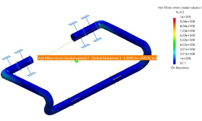
Рис. 5. Распределение напряжений в скобе
-
Fig. 5. Stress distribution in the bracket
При проектировании узла крепления необходимо учитывать, что сила зажима, приложенная к шнуру не должна вызывать в нем пластических деформаций, что ограничивает максимальное усилие зажима только упругими деформациями. Для определения силы упругости, определим напряжения в поперечном сечении
When designing the attachment unit, it is necessary to take into account that the clamping force applied to the cord should not cause plastic deformations in it, which limits the maximum clamping force to elastic deformations only. To determine the elastic force, let's determine the stresses in the cross section
F_ = k -Ad.
упругости жест ,
σ = E ⋅ ε .
where F упругости is the elastic force equal to the support reaction force N ; k жест is the stiffness factor; σ is the normal stress; E is the modulus of elasticity of the first kind; ε is the relative linear longitudinal deformation; Δ d is the linear deformation. However, the final results depend largely on the type and material of the cord, which may vary depending on the objectives.
Conclusion
In this work, we have developed a unit for attaching the brackets to the power spoke of the reflector. The knot can be used in a wide range of large-sized antennas, has a high manufacturability and versatility. The limiting ranges of tension forces and materials used in the unit were determined, as well as its strength and mass characteristics.
Further, the ergonomic characteristics can be improved to reduce the weight of the unit.
It is recommended to use the most universal version of a bracket made of titanium alloy VT16 with diameter of 22 mm, which can withstand up to 41,50 N of tension force, which gives considerable safety margin for the majority of design cases. But, based on technological and economic considerations, smaller diameter brackets made of AMg6, VT14 can also be used for lower tension forces.
References Design of the fastening assembly of the guys on the power spokes reflector
- Belonovskaya I. D. Kolga V. V., Yarkov I. S., Yarkova E. A. [Parametric analysis of an an-isogrid body of a spacecraft for cleaning the orbit from space debris]. Siberian Aerospace Journal. 2021, Vol. 22, No. 1, P. 94–105 (In Russ.).
- Zamyatin D. A., Kolga V. V. [Modeling the design of the reflector mast]. Reshetnevsky Read-ings: Proceedings of the XXIV Intern. scientific conf. (November 10–13, 2020, Krasnoyarsk). Krasnoyarsk, 2020, P. 21–22 (In Russ.).
- Kolga V. V., Yarkov I. S., Yarkova E. A. [Development of a thermal panel for a small space-craft for navigation support]. Siberian Journal of Science and Technology. 2020, Vol. 21, No. 3, P. 382–388 (In Russ.).
- Kolga V. V., Marchuk M. E., Lykum A. I., and Philipson G. Yu. [Optimization of the location of attachment points for the instrument panel of a spacecraft based on modal analysis]. Siberian Aerospace Journal. 2021, Vol. 22, No. 2, P. 328–338 (In Russ.).
- Kolga V. V., Marchuk M. E., Lykum A. I., Sommer S. A. [Optimization of the location of the interface points of the instrument panel of the spacecraft]. Innovations. The science. Education. 2021, No. 6, P. 1401–1405 (In Russ.).
- Kolga V. V., Marchuk M. E., Lykum A. I., Romanenko G. A. [On approaches to predicting the acoustic impact on the shell elements of the spacecraft]. Reshetnev readings: materials of the XXV In-tern. scientific conf. (November 10–12, 2021, Krasnoyarsk). Krasnoyarsk, 2021, P. 38–41 (In Russ.).
- Gryanik M. V., Loman V. I. Razvertyvaemye zerkal'nye antenny zontichnogo tipa [Deployable mirror antennas of umbrella type]. Moscow, Radio and Communications Publ., 1987, 9 p.
- Chebotarev V. E., Kosenko V. E. Osnovy proektirovaniya kosmicheskikh apparatov infor-matsionnogo obespecheniya [Fundamentals of designing information support spacecraft]. Krasnoyarsk, 2011, 348 p.
- Testoedov N. A., Kolga V. V., Semenova L. A. Proektirovanie i konstruirovanie ballistich-eskikh raket i raket nositeley [Design and construction of ballistic missiles and launch vehicles]. Krasnoyarsk, 2014, 308 p.
- Testoedov N. A., Khalimanovich V. I. et al. Sposob izgotovleniya razvertyvayemogo krupno-gabaritnogo reflektora kosmicheskogo apparata [Method for manufacturing a deployable large space-craft reflector]. Patent RF №2350518, 2009.
- Semenov Yu. P., Strekalov A. F. et al. Sposob sborki krupnogabaritnykh razvertyvayemykh kosmicheskikh reflektorov i tekhnologicheskoye prisposobleniye dlya formirovaniya otrazhayushchey poverkhnosti reflektora [A method for assembling large-sized deployable space reflectors and a technological device for forming a reflective surface of a reflector]. Patent RF № 2296396, 2007.
- Velichko A. I., Shendalev D. O. et al. Sposob izgotovleniya krupnogabaritnogo trans-formiruyemogo reflektora [A method of manufacturing a large-sized transformable reflector]. Patent RF № 2674386, 2018.
- Polukhin N. V., Bychkov V. I. et al. Sposob izgotovleniya krupnogabaritnykh razvertyvaye-mykh reflektorov i ustroystvo dlya formirovaniya krivolineynoy poverkhnosti reflektora [A method for manufacturing large-sized deployable reflectors and a device for forming a curved reflector surface]. Patent RF №2276823, 2006.
- Anuryev V. I. Spravochnik konstruktora mashinostroitelya. Tom 1 [Handbook of a machine builder's designer. Vol. 1]. Moscow, Mashinostroenie Publ., 2001, 53 p.
- Lopatin A. V., Rutkovskaya M. A. [Review of designs of modern transformable space anten-nas. Part 1]. Siberian Aerospace Journal. 2007. No. 2. P. 51–57 (In Russ.).
