Design truncated rectangular patch microstrip antenna for telecommunication base stations

Author: Wafaa Mohammed Hashim, Adheed Hasan Sallomi
Journal: International Journal of Wireless and Microwave Technologies @ijwmt
Article in issue: 4 Vol.9, 2019.
Free access
In this paper a truncated rectangular patch microstrip antenna with multiple slots has been proposed, to provide a wide impedance bandwidth, in addition to acceptable antenna performance parameters such as (gain and radiation pattern). FR-4 substrate is used to design the antenna structure, the substrate has thickness of 1.6 mm and relative permittivity of 4.3. By utilizing CST Microwave Studio Simulation softwer, the simulation procedure has been done. This antenna covers broadband from (0.94GHz to 3.4GHz), therefor it is suitable for operation in telecommunication base stations, and the antenna covers the GSM900, GSM1800, GSM1900, and IMT applications.
Microstrip Patch Antenna, Broadband Antenna, Telecommunication base stations, S-Parameter, Radiation Pattern
Short address: https://sciup.org/15016972
IDR: 15016972 | DOI: 10.5815/ijwmt.2019.04.01
Text of the scientific article Design truncated rectangular patch microstrip antenna for telecommunication base stations
Published Online July 2019 in MECS DOI: 10.5815/ijwmt.2019.04.01
The request for compact, broadband, low profile antennas has increased significantly in accordance with the proliferation of wireless communication technology, in recent years the microstrip patch antenna was proposed because of its light weight low profile, and low cost [1].
In general a traditional microstrip antenna consists of a conducting patch printed on substrate with a ground plane below the substrate, the materials have been used to fabricate metallic patch (usually Cu or Au), patch may be geometrical shapes such as rectangular, circular, triangular, elliptical, helical, ring etc [2]. However, main operational abuse of the microstrip antennas involve lower power gain, lower efficiency, higher quality
* Corresponding author. Tel.:
factor (occasionally in excess of 100), pauper polarization pureness, pauper scan performance, pseudo feeding radiation and frequency band so narrow [3]. A lot of investigations have been done to increase the bandwidth of these antennas in recent years, some of these techniques involve the employment of thick substrates with lower dielectric constants and insertion of slots in the patch [4]. There are a lot of ways for feeding the proposed antennas, the CPW, microstrip, slotline, coaxial probe are some feeding methods [5]. The major features of using microstrip transmission line feeding is that it is very simple to manufacture and easy for matching by controlling the inset position and comparatively easy to model [6, 7]. The patch length, the effective patch length, the effective relative dielectric constant and the characteristics can be expressed [8].
W= Co_( £ r +1 ) l/2
2f 2 7
L = L eff - 2 AL
L eff

AL = Ax 0.412 2=zz+0:»-"+^
(E reff —° ■ 258)(w/h+0.8)
£ r + 1 £ r -1 hX-1/,,
E reff = — + —(! + 12-) /2
Where
W: The patch width
ε r : The substrate dielectric constant
L: The patch length
-
h: The height of the substrate
-
2. Truncated Rectangular Patch Antenna Structure
L eff : The patch length effect f r : The resonance frequency ε reff : The effective dielectric constant
However, many researches where carried in the field of microstrip antenna at the present time. Most of these researches focus on improving the bandwidth of the antenna such as [9, 10, 11, 12]. The improvement achieved was at different levels according to the antenna shape and characteristics. However, in this paper the widest band and size reduction are achieved as compared with other researches. The ultimate goal is to reduce the antenna size and improve the antenna characteristics such as bandwidth and gain.
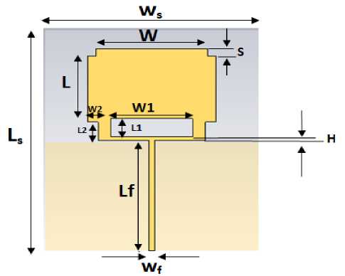
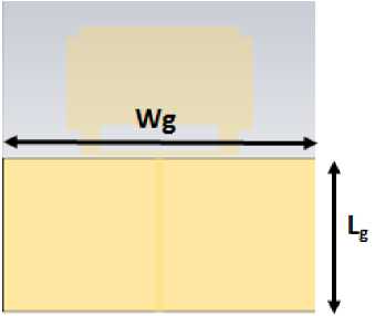
The proposed antenna consists of a truncated rectangular patch, rectangular shape with dimensions W 2 , L 2 is truncated at the corners of the bottom part of the patch, and the square shape with dimension S is cut at the corners of the top part of the patch. Rectangular slot with dimensions W 1 , L 1 is inserted at a distance H from the bottom side of the patch. FR-4 substrate with dielectric constant equal to 4.3 and partial ground structure has dimensions L g , W g are used to design this antenna. The proposed antenna is shown in the Fig. 1.
(a)
Fig.1. Proposed truncated rectangular patch antenna (a) Front view, (b) Back view.
(b)
-
3. Simulation Process
-
3.1 The Influence of Feeder Length (L f )
-
3.2 The Influence of Position of Rectangular Slot from the bottom edge of the Patch (H)
Because the initial parameters of the antenna don't give the best result, so trying to improve the performance is done by changing the parameters and chooses the best one by an optimization process.
The first parameter can be optimized is the feeder length, Fig. 2. shows the simulation of S-Parameter for different values of feeder length. The optimization process is done by considering L g =60mm, W g =85mm, H=1 mm, W 1 =38mm, W f =2mm, from the curve it can be noticed that when the feeder length is increased, further improving the impedance matching between the feed line and the patch can be obtained. The optimum value is L f =60mm, at which acceptable bandwidth can be achieved from 1GHz to 1.5 GHz and another band from 2GHz to 3.7 GHz.
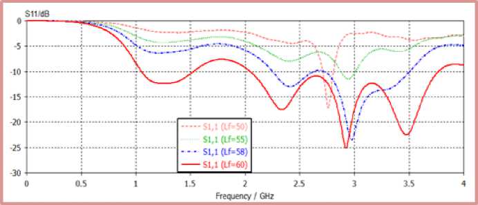
Fig.2. Simulation S-Parameter against frequency for a truncated rectangular patch at various values of L f
The second parameter can be optimized is (H), Fig.3 shows the simulation of S-Parameter versus frequency for different values of (H), using optimized value of feeder length that can be obtained from the previous simulation is Lf=60mm, and other parameters remains at the same values as L g =60mm, W g =85mm, W 1 =38mm, Wf=2mm. It is observed that the rectangular slot at a distance 2 mm from the lower edge of the patch will improve the impedance matching from 2.4 GHz to 2.8 GHz significantly.
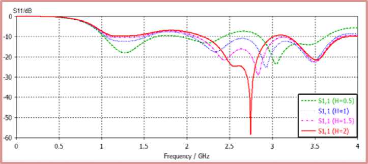
Fig.3. Simulation S-Parameter against frequency for a truncated rectangular patch at various values of H
-
3.3 The Influence of Rectangular Slot Width (W1)
-
3.4 The Influence of Feeder Width (W f )
-
3.5 The Influence of Ground Plane Length ( Lg)
The third parameter was optimized is the rectangular slot width (W1), the optimization process is done by using the optimized values that can be obtained previously as L f = 60mm, H=2mm, and fixing other parameters as W f = 2mm, W g = 85mm, L g =60 mm. Fig. 4 shows the simulation of the S-Parameter versus frequency for different values of rectangular slot width, it is noticed that the rectangular slot is important parameter that affects the impedance matching, it can be noticed bad impedance matching without the rectangular slot. The optimum value of the slot width is W 1 =38mm .
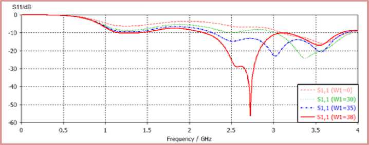
Fig.4. Simulation S-Parameter against frequency for a truncated rectangular patch at various values of W 1 .
The fourth parameter can be optimized is the feeder width using optimized values of H =2mm, Lf=60mm, W 1 =38mm with fixing other parameters on L g =60mm, W g =85mm. Fig. 5 shows simulation of S-Parameter versus frequency for different values of feeder width (W f ), it can be noticed that increasing the value of (W f ) will further improve the return loss of the proposed antenna, consequently wider bandwidth from 1GHz to 1.3GHz and from 1.8GHz to 3.7GHz, will be achieved at the optimum value of Wf=2.8mm.
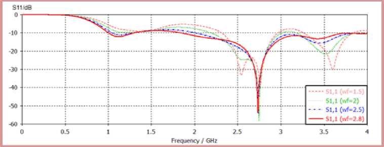
Fig.5. Simulation S-Parameter against frequency for a truncated rectangular patch at various values of W f
The fifth parameter can be optimized is ground plane length (Lg), it is an important parameter to determine the performance of the antenna, by using optimized values of H=2mm, L f =60mm, W f =2.8mm, W 1 =38mm, with fixing W g =85mm. Fig. 6 shows the simulation of S-Parameter versus frequency for different values of ground plane length, it is observed that decreasing the value of L g , leads to achieving good impedance matching. The optimum value of L g is 59mm.
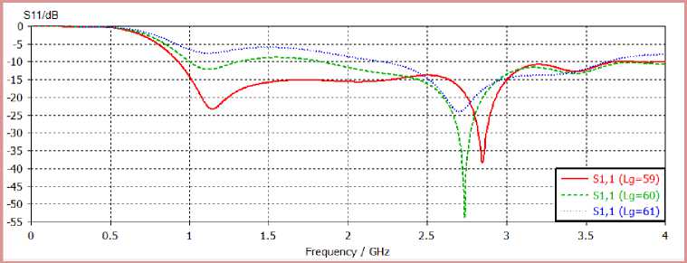
Fig.6. Simulation S- Parameter against frequency for a truncated rectangular patch at various values of Lg.
-
3.6 The influence of Ground Plane Width (W g )
-
4. Inserting T slot to the Patch of the Antenna
The last parameter can be optimized is the ground plane width, The optimization process is done by using the optimized values that were obtained from previous simulation process as H =2mm, L f =60mm, L g =60mm, W f =2.8, W 1 =38mm. Fig. 7 shows the simulation of the S-Parameter versus frequency for different values of ground plane width, from curve it is observed full-width ground plane along the substrate width gives optimum value better than others simulation values. The optimum value is Wg=100mm, at which a broadband from 0.93 GHz to 3.4 GHz with an acceptable return loss can be achieved.
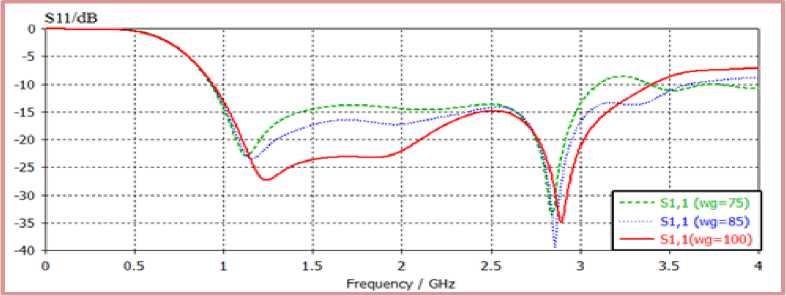
Fig.7. Simulations S-Parameter against frequency for a truncated rectangular patch at various values of W g
Optimum parameters values of the proposed a truncated rectangular patch is shown in Table.1
Table 1. The optimum values for a truncated rectangular patch
|
Parameter |
Value |
Description |
|
L s |
120mm |
Substrate length |
|
W s |
100mm |
Substrate width |
|
W |
56mm |
Patch width |
|
L |
36mm |
Patch length |
|
W 1 |
38mm |
The width of the rectangular slot |
|
L 1 |
10mm |
The length of the rectangular slot |
|
H |
2mm |
The height of the rectangular slot from the lower edge of the patch |
|
W 2 |
5mm |
The width of the rectangular that cut from corners of the lower edge of the patch |
|
L 2 |
10mm |
The length of the rectangular that cut from corners of the lower edge of the patch. |
|
S |
4mm |
Dimensions of square that cut from the corners of the upper edge of the patch |
|
W f |
2.8mm |
Feeder width |
|
L f |
60mm |
Feeder length |
|
L g |
59mm |
Ground plane length |
|
W g |
100mm |
Ground plane width |
Inserting slots to the patch of microstrip antenna improve its performance significantly because the slots change the current distribution along the patch and introduce longer current paths. The position of the slot is oriented with respect to surface current, in this structure the best position is the top of the patch. The dimensions of the T slot were chosen by an optimization process, Fig. 8 shows the structure of the antenna with the T slot and the dimension of the slot.
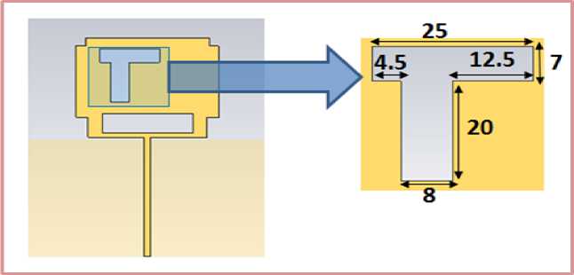
Fig.8. The structure of the truncated patch antenna with T slot and the dimensions of the slot
Fig. 9 shows the influence of inserted T slot in the patch of the antenna on its performance, it can be noticed the influence of the T slot on the gain, from the 0.93 GHz to 2.1 GHz the gain doesn’t change, but from 2.2 GHz to the end of the band, the gain will increase significantly.
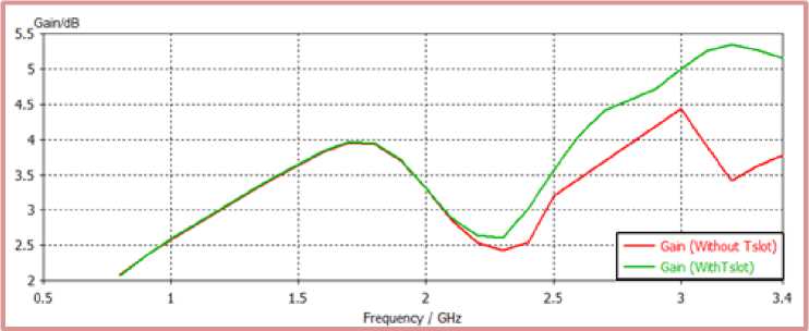
Fig.9. The gain of a truncated rectangular patch antenna with and without T slot
-
5. Characteristics of a Truncated Rectangular Patch with T slot
-
5.1. Current Distribution
-
-
5.2. E-plane and H-plane radiation patterns
-
6. Comparison among the proposed antennas and Other Article References
The current distribution for the proposed antenna at frequencies 0.94 GHz, 2.1 GHz, 2.4 GHz, and 3.4 GHz is shown in Fig.10. Fig.10a shows the current distribution at 0.94 GHz, it can be noticed the maximum current is 51.2A/m, and most concentration of the current at the feed line and lower edge of the patch with a minimum concentration of the current at the top of the patch. Fig.10b shows the current distribution at 2.1 GHz, it can be noticed maximum current is 39.7A/m, and most concentration of the current at the feed line, the lower edge of the patch and around the rectangular slot, minimum concentration of the current at the top of the patch and around T slot . Fig.10c shows the current concentration at 3.4GHz, it can be noticed maximum current is 37A/m, and maximum concentration of the current at some parts of the feed line and around the rectangular and T slots.
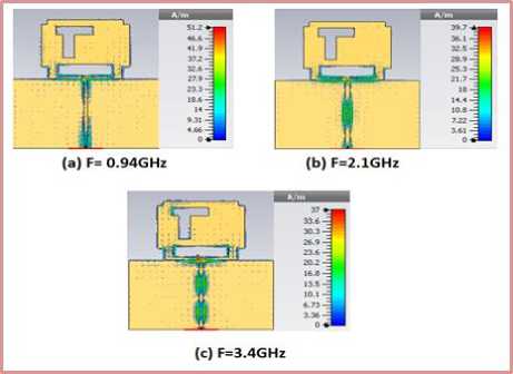
Fig.10. Current distribution of the truncated rectangular patch antenna with T slot for different frequencies
E-plane and H-plane for frequencies 0.94GHz, 2.1GHz, 3.4GHz are shown in Fig.11. Fig.11a shows E-plan and H-plane for 0.94GHz, the value of E-plane major lobe is 2.54dBi, the direction of major lobe is -177 degree, angular width (3dB) is 83 degree, the value of H-plan major lobe is 1.21dBi, the direction of major lobe
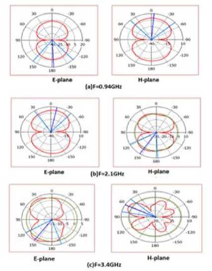
Fig.11. E-plan and H-plane for a truncated rectangular patch at different frequencies is -5 degree, and angular width (3dB) is 90.5 degree. Fig.11b shows E-plane and H-plane for 2.1GHz, the value of E-plan major lobe is 3.32dBi, the direction of major lobe is -12 degree, angular width (3dB) is 75.2 degree, the value of H-plane major lobe is 1.07dBi, the direction of major lobe is 146 degree, angular width (3dB) is 65.4, side lobe level is -2dB. Fig.11c shows the E-plane, H-plane for 3.4GHz, the value of E-plane major lobe is 3.81dBi, the direction of main lobe is 144 degree, angular width (3dB) is 77.6 degree, side lobe level -1.7dB, the value of H-plane major lobe is 6.09dBi, the direction of main lobe is 62 degree, angular width (3dB) is 32.3 degree, side lobe level is -2.6dB.
Table 2. shows a comparison among the proposed truncated rectangular patch antenna and Ref [9], Ref [10], Ref [11], Ref [12] in terms of size, bandwidth and gain. It can be seen that the proposed antenna has the best overall results as compared with the reference antennas.
Table 2. Comparison between truncated rectangular patch microstrip antenna and other article references
|
Works |
Size |
Band (GHz) |
Max Gain |
|
Reference[9] |
- (130×130) mm2 |
(1.750-1.870) (1.920-2.170) |
7.18dBi |
|
Reference [10] |
(1.850-1.990) |
- |
|
|
Reference [11] |
(300×300×73.175)mm3 |
(1.710-1.880) |
7.9dBi |
|
Reference [12] |
(136×70×0.8) mm3 |
(1.920-2.170) |
7.1dBi |
|
Truncated rectangular patch |
(100×120×1.5) mm3 |
(2.400-2.484) |
1.4dBi |
-
7. Conclusions
Broadband truncated rectangular patch microstrip antenna using multiple slots has been proposed. The performance of the antenna can be developed significantly, by optimize all relevant parameters of the antenna and utilizing an appropriate slots size on the patch's surface, It is found that using rectangular slot enhances the impedance matching and consequently increases the bandwidth and using T slot enhances the gain of the antenna. This antenna offers the gain ranging from (2.5 dB to 3.7 dB ), but by adding T slot to the upper of the patch the gain is improved, new gain after adding T slot is from (2.5 dB to 5.1dB).
References Design truncated rectangular patch microstrip antenna for telecommunication base stations
- Jone Wiley &sons. Constantine A. Balanis, third edition, "Antenna Theory Analysis and Design", 2005.
- Ankur Kaushal, Sachin Tyagi, "Microstrip patch antenna its type merits demerits and its applications", International Journal of Engineering Sciences & research technology, July 2015.
- Y. Entiefa Mansour, "Single Slot Dual Band Microstrip Antenna for WIMAX Application," Atilim University, thesis 2014.
- V. Lanka Subrahmanya, "The Rectangular Microstrip Patch Antenna, "Boras, Swedish, thesis 2009.
- Nasimuddin, Microstrip Antennas. India: Intech publisher, 2011.
- Prof. R. P. Labade S. M. Vanam, "Parametric Analysis and Design of Rectangular Microstrip Patch Antenna for Ultra-wideband Application," International Journal of Microwaves Applications, vol. 3, no. 3, pp. 17- 20, May-June 2014.
- T. A. Milligan, Modern Antenna Design, 2nd ed. Hoboken, New Jersey: John Wily & Sons, 2005.
- Constantine A. Balansis, antenna theory: analysis and design 3rd ed. Hoboken, New Jersey: John Wiley& Sons, 2005.
- Joo-Seong Jeon, Sang-Hoon Park, KTF R&D Group, Madu-Dong, Ilsan-Gu, and Koyang-Shi "Wideband Antenna for PCS and IMT-2000 Service Band", IEEE, 2004.
- Amer Bzeih, Soubhi Abou Chahine, Karim Y. Kabalan, Ali El-Hajj, and Ali Chehab, " An Improved Broadband E patch Microstrip Antenna for Wireless Communications", American Geophysical Union, Radio Science ,vol. 42, RS6001, 2007.
- Mohamed S. El-Gendy, Haythem H. Abdullah, and Esmat A.Abdallah," Microstrip Slot Antenna for Mobile Base Station", Progress In Electromagnetics Research Symposium Proceedings, Taipei, March, 2013.
- Sultan Shoaib, Imran Shoaib, Xiaodong Chen and Clive G. Parini, "Compact and Printed Multiband Antennas for 2G/3G/4G Smartphones", IEEE, 2015.
