Development and implementation of the technical accident prevention subsystem for the smart home system

Author: Vasyl Teslyuk, Vasyl Beregovskyi, Pavlo Denysyuk, Taras Teslyuk, Andrii Lozynskyi
Journal: International Journal of Intelligent Systems and Applications @ijisa
Article in issue: 1 vol.10, 2018.
Free access
The structure of the technical accident prevention subsystem for the smart home system has been developed in the article. The subsystem model based on Petri network, model based on neural network and physical model using the Arduino microcontroller have been realized in the development process. The subsystem research results with the use of the developed models, soft- and hardware tools are also presented.
Arduino microcontroller, neural network, models, Petri net, smart home system, home automation
Short address: https://sciup.org/15016447
IDR: 15016447 | DOI: 10.5815/ijisa.2018.01.01
Text of the scientific article Development and implementation of the technical accident prevention subsystem for the smart home system
Published Online January 2018 in MECS
The technical development, energy conservation necessity to meet people’s requirements and demands for their own apartments have led to emergence of smart home technologies [1] – [4]. The modern smart home system includes the following subsystems: lighting, climate control, security, technical incidents prevention subsystem and others [5] – [7]. There are various options for the above-mentioned subsystems implementing depending on the consumers needs, characteristics, environmental features, existing destabilizing factors, etc.
On the one hand, such collecting, processing and environment effecting system includes technical microelectrical tools (computers, microcontrollers, transducers, actuators, cameras, etc.), on the other one, to ensure the intellectual properties it has the appropriate software. The level of such systems intellectualization increases with time. Therefore, for the smart home system implementation neurocontrollers [8 - 11] use is the an important and urgent task.
Accordingly, during the implementation of technical accident prevention subsystem for the smart house system there is necessity to solve the following problems:
-
• It is necessary to develop a structure of technical accident prevention subsystem, which will be
based on modular principle. This will help to improve the process of development;
-
• It is necessary to build an algorithm of the subsystem and structural model based on the theory of Petry nets, which will help to explore the dynamic of the subsystem in technical accident prevention subsystem;
-
• It is necessary to develop a model based on artificial neural networks for processing fuzzy data from the sensor subsystem;
-
• It is necessary to develop a software of technical accident prevention subsystem for smart house systems and technical support, which will ensure all functions and is cheap.
-
II. Development of the Technical Accident Prevention Subsystem Structure for Smart Home System
As it has already been mentioned the smart home is a complex system that controls various processes in a house, namely: climate, lighting, security and others. Its functions also include ensuring the home safety and security. The smart home should be able to detect dangerous situations, conflicts and hazardous situations, as well as to contribute building protection. The technical accident prevention subsystems for smart homes have been developed and researched with this aim.
Many publications are devoted to developing a system of protection of "smart" building from technical failures [12] - [15]. In particular, in the paper the authors propose a technical solution to protect data in distributed systems [12]. The paper is devoted to the issue of authorization and authentication in medical systems data [13]. The technical solutions how to protect data in the energy consumption system [14] and "smart" city [15] are described. However, the proposed technical solutions are expensive and do not include the problem when not truth data are received from the smart home sensors.
The smart home system should be able to detect the danger and act according to the situation. For this aim, e.g. in the kitchen, there are the following sensors:
-
• fire sensor;
-
• smoke and gas sensor;
-
• water leak detector, some other sensors could be added in the future subsystem improvement.
To solve the above mentioned problems the technological accidents prevention subsystem (TAP) can control the following appliances:
-
• the electric gas trap key;
-
• the water supply trap key;
-
• the fire prevention system;
-
• the air hole, etc.
In addition, in the case of one of the dangerous situations the subsystem should submit a signal to user. The sound and light signals can be used for this purpose. Let assume that the subsystem can manage the sound and two lighting alarms (one is for water leak and the other two for possible fire, smoke and gas leak). An example of the developed simplified TAP subsystem structure with the above components is shown in Fig. 1.
Here are the possible TAP subsystem scenarios.
-
1) If fire operations starts in the kitchen, fire and smoke sensor should react. Then the gas should be turned off, the fire protection system switched on and sound and light signals sent to the house owner.
-
2) If there is water leak, the corresponding sensor should react. Then water should be blocked, sound and light signals sent to the user.
-
3) If there is gas leak, then smoke/gas sensor should react. Then gas should be blocked and the air hole turned on to reduce the smoke and gas concentration and also sound and light alarms should be sent to the house owner.
-
4) If there is smoke leak, the smoke/gas sensor should react. Then gas should be blocked and the air hole turned on to reduce the smoke and gas concentration, and sound and light alarms should be sent to the house owner.
-
III. Development of the Technical Accident Prevention Subsystem Structure for Smart Home System Based on Petri Nets
With the aim to study TAP subsystem possibilities and ability to properly perform its tasks, its model at design system level based on colored Petri nets has been developed [16] – [18].
The model based on the colored Petry nets can be described using the following expression:
CPN = {PoS, TranS, ArcS ,BBPoSMark, TpS,PosTpS,ArcStpS,CnD}
where PoS = {p1,p2,...,pn} - a set of position (states);
ArcS – a set of curves, input and output arcs according to the transitions;
BBPoSMark – set, which sets the initial marking of Petry nets;
TpS – a set of types;
PoSTpS – a set that reflects the set of available positions in the network;
ArcSTpS – a set of the markers that stimulate the transition, or indicate what types of tokens need to be generated by the transition;
Cnd – a set of the markers that need to be stimulated by the transition, or indicate what types of tokens need to be generated;
m – conversions in colored Petri nets.
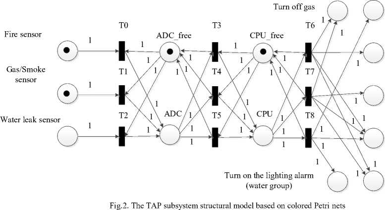
Colored Petri nets are used to distinguish signals from each of the sensors, namely (for the developed subsystem): red is the fire sensor signal, yellow is the smoke/gas sensor signal, blue is the water leak sensor signal.
The developed model based on Petri nets can be roughly divided into 4 parts, each with its own function: the sensor unit includes sensors and analog-to-digital converter transitions (ADC); the block of analog-to-digital converter that contains ADC and transition to the central processing unit (CPU).
There is consecutive processing of signals from each of sensors implemented in this block:
-
- CPU block, which contains CPU and transitions to actuators. The consecutive sensors data processing is implemented in this block;
-
- actuator block, which contains all actuators in accordance with the TAP structure.
The constructed model works according to the algorithm with the following main stages. Thus, when one of the sensors records a negative change in the smart house environment, it waits until the ADC is free and then transmits this data for ADC processing. Then the digital signal from a sensor is stored in the buffer until the CPU will be free, and then data will be sent to the CPU, which will decide in accordance with the algorithm what should be done or which control signal should be given to the actuators. The next stage is transferring of the processed data to the actuators, which are chosen for troubleshooting and direct sending control signals.
During TAP subsystem study with the use of the model based on colored PN, the state reachability graph [19], which allows to estimate the subsystem`s performance dynamics and other original settings (fig. 2) at the system level of smart house automated design, has been constructed.
Information model of reachability graph can be represented this way:
Gr =(5, L), where S – set of states (places);
L – set of links (transitions) between the states of the system (elements).
Assuming that the number of states of the system is finite and equal to number n , then
n
5 = U 5, i=1
where S – is i -th state of system.
Since that the reachability graph refers to directed graphs, we define links between current system. We now describe the number of transitions l which we is use for lower index and for definite states of system. Here upper cases should be used. Then we have, the first index which denotes the initial state of system and the second index – the final state of the system. Therefore, the set of relations between the states of the system includes the
l following elements: L = UL , where l i=1
transitions.
– a number of
The information about current state and the state which we will get as a result of triggering i-th flow is described
l like this: L = ULn~i,out" i=1
i , where in
i – a number of
initial system state of i -th transition; out_i – a number of final system state of i -th transition.
As it can be seen in the reachability graph [20] everything starts with S0 state. This state conforms to the initial Petri nets marking presented in Fig. 4. Depending on the random processes the system can have 4 directions, namely: reach S5 or S6 states or S7 or S8 once. Regardless of the path, all the states eventually reach the final state S13 which describes the system final time. In this case, it is necessary to overlap the gas, to turn on the fire protection system, the hood, and sound-lighting signalization system.
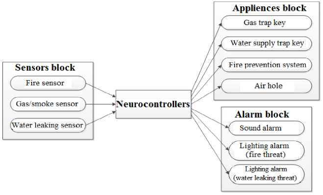
Fig.1. The smart house TAP subsystem structure
Turn off water
Turn on the fireprevention system
Turn on the air hole
Turn on the sound alarm
Turn on the lighting alarm (fire group)
-
IV. Development of the Neural Network Model for Implementation of the Functions of the Smart Home Accident Prevention Subsystem
For the TAP subsystem management the neural network [20], [21], trained to read data from the sensors and react according to the above mentioned operation, is used. The artificial neural network of Perceptron multilayer type is used [22]. An example of the developed model of the simplified neural network is shown in Fig.6.
In general, the structural model can be described as following SNM motorcade:
Str _ SNM =< ID,N _ Fun, Par, N > , (2)
“n” – due to none;
“o” – original edge;
“i” – input edge.
For example, the corresponding matrix is illustrated in fig. 3.
-----i i i --------
-----i i i --------
-----i i i --------
-----i i i -------- ---------i i i i i i i o o o o -----i i i i i ii
-
o o o o -----i i i i i ii
-
o o o o -----i i i i i ii
where ID = id(i) - a set identifiers SNM ( i = 1,N ); N Fun = n fun(i) - a set of the neurons functions; Par = par(i) - a set of the neurons parameters;
N – the numbers of neurons on the SNM.
To represent the matrix of the connections berween neurons, we use the matrix size (N + 1)*(N + 1) .
Each element of the matrix can take one of three possible values:
----o o o o --------
----o o o o --------
----o o o o --------
----o o o o --------
----o o o o --------
----o o o o --------
----o o o o --------
-
Fig.3. Settings matrix of connections between neurons based on artificial neural network
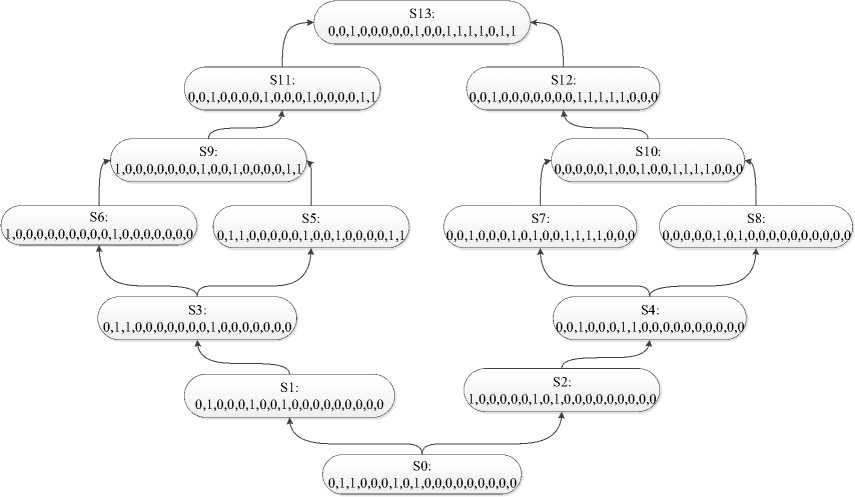
Fig.4. An example of the reachability graph of the subsystem work states
Therefore, as an outcome of the neural network education the weight coefficients for all the relations between neurons have been obtained, the structure of which is presented in Fig. 6. For instance, the values of weight coefficients between the first and fifth neuron ( w1,5 ) ties, sixth and seventh ones ( w1,6 ) are equal to w15 = 9.23 , w1^ = 7.48 , w17 = 1,37 , where indexes -the neuron number in the designed network. In addition, the outputs values of neural networks, e.g. for the second test from Table. 1, are the following: y[0 =0.0036 , y[1=0.9936 , y[2=0.0030, y[3]=0.0011, y[4"=09965, y[5=0.0036 , y[6"=09936.
After rounding the results the obtained from the neural network outputs, we will gain the following state {0, 1, 0, 0, 1, 0, 1}. With the obtained data we can see that the developed neural network is working properly and correctly.
-
V. Development of the Neurocontroller Software Model
The neurocontroller software (SW) structure (fig. 7) contains the network initialization block, where weights, connection and neurons parameters are initialized. The port initialization block operates only once, it establishes the ports status and initial values.
The second part of the software is divided into a number of separate subtasks, such as data reading, where the sensor data is processed; sensor testing, data for conversion into the required type, namely:
-
• data normalization which performs normalization according to the educational network sample;
-
• network start which performs data entry into the network and its passing through the network;
-
• result output, which retrieves the results from the network and displays them through the serial port;
-
• control command formation which manages the output ports depending on the obtained results;
-
• delay formation which creates the previously defined (2 seconds) delay, then the program is run again.
For the neurocontroller implementation the microcontroller, which performs the same program in a cycle for an unlimited number of iterations has been applied (Fig.5. gives the fragment of the short listening of neurocontroller program code). For the neurocontroller software realization C++ [23] is used that provides fast and flexible microcontroller SW development. The neural network software implementation enables the artificial neural network modification and neurocontroller functionality to increase.
-
V I. Development of the Physical Model for Research of the Created Smart House Accident Prevention Subsystem
The most applicable data has been obtained from the system physical models. Therefore, for the model realization the following sensors were selected:
-
• gas and smoke sensors MQ-2;
-
• fire sensor - Arduino Compatible Mini Flame Fire Wavelength Sensor;
-
• homemade water leak sensor based on the principle of circuit closure with salt solution water.
The selected sensors are compatible with the microcontroller Arduino Duemilanove 328 [24] – [27]. These sensors are cheap and simple in use and results processing. The light-emitting diodes are used to display the corresponding actuator activation.
An example of the physical model is shown in Fig. 9. Using the developed physical model, the presentation of input, internal and output signals of the neural network throughout serial port, it is possible to check practically the realization of neurocontroller functions and their corrspondence to technical requirements. For example, in the case of smoke and fire sensor activation the output values in digital format will be:
Sensor_Smoke=425 , Sensor_Water=85 , Sensor_Fire=0 .
Accordingly, the output signal values will be as ne[0=1.000, ne[1=0.000 , ne[2= 0 000 , ne[3==10)00, ne[4=1.000, ne[5=0.003 , ne\_6=0.677 , ne[7=0.988, ne[8 "=1.000 , ne [9=0.998 , ne[10 "=0.002 , ne[11=0.994 , ne[12==00)05 , ne[13 ==10)00 , ne[14 ]-0.997 , ne[15]=0.002 , that correspond to the developed tests in Table 1. The appropriate results are provided for all the tests that confirm the conformity of the designed theoretical and physical models in development process of the technical accident prevention subsystem for smart houses in the neuroconrtoller form.
#define FireSensor 12 // a port of initialization for fire sensor #define SmokeSensor A0 // a port of initialization for smoke and gas sensor
-
# define WaterSensor A1 // port initialization for water leak detector
#define Led1 11 // a port of initialization for the 1-th actuator #define Led2 10 // a port of initialization for the 2-th actuator #define Led3 9 // a port of initialization for the 3-th actuator
-
# define Led4 8 // a port of initialization for the 4-th actuator
-
# define Led5 7 // a port of initialization for the 1-th alarm box
-
# define Led6 6 // a port of initialization for the 2-th alarm box
-
# define Led7 5 // a port of initialization for the 3-th alarm box
-
#define Sum_Good 4 // a port of initialization for self-reviving status system
3.3988706207830064, -4.269634668533792, 0.0, 0.0, 0.0, 0.0, 0.0, 0.0, 0.0, 0.0},
#define Sum_Bad 3
int FireStatus; // a fire danger status int SmokeStatus; // a smoke and gas danger status int WaterStatus; // a water danger status int val = 0;
const int netSize = 16; // the number of neurons in the network const int cntIn = 3; // the number of input neurons const int cntOut = 7; // the number of output neurons //----- NET parameters ------------------- const float value[netSize][netSize] = // adjacency matrix
(Showing Weight of trransitions)
{
{0.0, 0.0, 0.0, 0.0, 0.0, -4.689294795590509, -
{0.0, 0.0, 0.0, 0.0, 0.0, 9.231720568364084, -
-
7 .477936003780324, -1.2911886237754364, 0.0, 0.0, 0.0, 0.0, 0.0, 0.0, 0.0, 0.0},
{0.0, 0.0, 0.0, 0.0, 0.0, 0.09770150867223379,
-
8 .451531384220349, -1.6114376928300227, 0.0, 0.0, 0.0, 0.0, 0.0, 0.0, 0.0, 0.0} }
-
Fig.5. The fragment of the short listening of neurocontroller program code
Water leaking sensor data
Balance neurons
Gas/Smoke sensor data
Fire sensor data
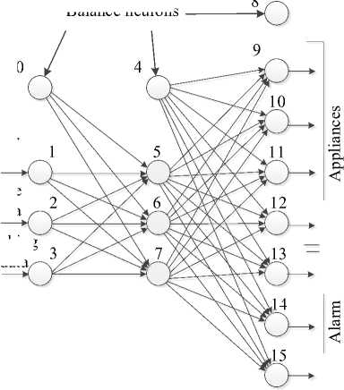
Fig.6. The neural network structure
Turn off gas
Turn off water
Fire-prevention system
Air hole
Sound alarm
Lighting alarm (fire group)
Lighting alarm (water group)
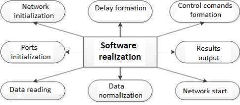
Fig.7. The neurocontroller software structure

Fig.8. Physical model sample
-
VII. Conclusions
-
1. A structure and an algorithm of the technical accidents prevention subsystem for a smart home have been developed, which uses the modular principle and allows to quickly and efficiently modify and improve the subsystem.
-
2. A model of the technical accidents prevention subsystem for a smart home has been developed, which is based on the Petri networks theory and enables to explore the subsystem’s performance dynamics at the system
-
3. A model of the technical accident prevention subsystem for a smart home has been designed, which uses an artificial neural network based on multilayer Perceptron which enables to process fuzzy and unstructured data from the sensor blocks.
-
4. A software structure and a physical model of the technical accident prevention subsystem for smart houses in the neuroconrtoller form has been developed, that uses the Arduino microcontroller and the programming model based on the artificial neural network and enables investigating the built models adequacy and performance, reliability and functionality of the developed subsystem.
level of automated design.
References Development and implementation of the technical accident prevention subsystem for the smart home system
- M. Chan, D. Esteve, C. Escriba, E. Campo, “A review of smart homes—Present state and future challenges.” Computer Methods and Programs in Biomediscine, Vol. 91, pp. 55-81, 2008.
- C. Wilson, T. Hargreaves, R. Hauxwell-Baldwin, “Benefits and risks of smart home technologies”, Energy Policy, Vol. 103, pp. 72–83, 2017.
- N. Noury, G. Virone, P. Barralon, J. Ye, V. Rialle, J. Demongeot, “New trends in health smart homes” in Proc. of the 5th International Workshop on Enterprise Networking and Computing in Healthcare Industry (Healthcom '03), June 2003, pp. 118–127.
- Y. Liu, B. Qiu, X. Fan, H. Zhu, B. Han, “Review of Smart Home Energy Management Systems.”, Energy Procedia, Vol. 104, pp. 504 – 508, 2016.
- B. Danny, Hurley, “Smart Homes For Dummies”, Third Edition, John Wiley & Sons, 432 p., 2011.
- A. Mahmoud,. “Al-Qutayri Smart Home Systems”, Publisher: InTech, 194 p., 2010.
- E. I. Batov, “The distinctive features of "smart" buildings.”, Procedia Engineering, Vol. 111, pp. 103 – 107, 2015.
- R. Aharonov, L. Seyev, I. Meilijson, E. Ruppin “Localization of function via lesion analysis”, Neural Computing, vol.15, pp.885-913, 2003.
- S. Doncieux, J.-A. Meyer, “Evolution of neurocontrollers for complex systems: alternatives to the incremental approach”, in Proceedings of The Intelligence and Applications (AIA 2004), 2004b, 18.
- M. Jalili-Kharaajoo, R. Mohammadi-Milasi “Design of Simple Neuro-controller for Global Transient Control and Voltage Regulation of Pawer Systems”, International Journal of Control, Automation, and Systems, vol.3, no2 (cpecial edition), pp.302-307, June 2005.
- D. Floreano, F. Mondada, “Evolutionary Neurocontrollers for Autonomous Mobile Robots”, Neural Networks, vol.11, num.7-8, pp.1461-1478, 1998.
- R. Roman, J. Zhou, J. Lopez, “On the features and challenges of security and privacy in distributed internet of things”, Computer Networks, vol.57, pp. 2266–2279, 2013.
- S. R. Moosavi, T. N. Gia, A.-M. Rahmani, E. Nigussie, S. Virtanen, J. Isoaho, H. Tenhunen, “SEA: A Secure and Efficient Authentication and Authorization Architecture for IoT-Based Healthcare Using Smart Gateways”, Procedia Computer Science, vol.52, pp. 452 – 459, 2015.
- K. Thananunsophon, B. Mangalabruks, Y. Fujii, P. P. Yupapin, “Community Monitoring and Security using an Intelligent Camera in EAT Smart Grids”, Procedia Engineering, vol. 8, pp. 332–336, 2011.
- A. S. Elmaghraby, M. M. Losavio, “Cyber security challenges in Smart Cities: Safety, security and privacy”, Journal of Advanced Research, vol. 5, pp. 491–497, 2014.
- V. M. Teslyuk, V. V. Beregovskyi, A. I. Pukach, “Development of smart house system model based on colored Petri nets”, in Proc. of International Seminar/Workshop on Direct and Inverse Problems of Electromagnetic and Acoustic Wave Theory, DIPED’2013, Lviv, Ukraine, September 2013, P. 205 – 208.
- M. Diaz, “Petri Nets: Fundamental Models, Verification and Applications”, John Wiley & Sons, 768 p., 2010.
- K. Jensen, L. M. Kristensen, “Coloured Petri Nets: modelling and validation of concurrent systems”, 1st edition, Springer, 395 p., 2009.
- V. Teslyuk, P. Denysyuk, Hamza Ali Yousef Al Shawabkeh, A. Kernytskyy, “Developing Information Model Of The Reachability Graph”, in. Proc. of the XVth International Seminar / Workshop Of Direct And Inverse Problems Of Electromagnetic And Acoustic Wave Theory, Tbilisi, Georgia, 2010, P. 210 – 214.
- H. Mohamad, “Hassoun Fundamentals of Artificial Neural Networks”, MIT Press, 511 p., 1995.
- A. Pukach, V. Teslyuk, R. Tkachenko, R.-A. Ivantsiv, “Implementation of neural networks for fuzzy and semistructured data”, in. Proc. of the XI Intern. Conf. on The Experience of Designing and Application of CAD Systems in Microelectronics, Lviv – Polyana, Ukraine, 2011, P. 350 – 352.
- F. Rosenblatt, “The Perceptron: A Probabilistic Model for Information Storage and Organization in the Brain”, Cornell Aeronautical Laboratory, Psychological Review, v.65, No. 6, pp. 386—408.
- W. Savitch, “Absolute C++”, 4th Edition, 736 p., 2009.
- J. A. Kornuta, M..E. Nipper, J. Brandon, “Dixon Low-cost microcontroller platform for studying lymphatic biomechanics in vitro”, Journal of Biomechanics, 46, pp.183–186, 2013.
- Tariq AL-Kadia, Ziyad AL-Tuwaijrib, Abdullah AL-Omran, “Arduino Wi-Fi network analyzer”, Procedia Computer Science, 21, pp. 522 – 529, 2013.
- A. Z. Jidin, N. M. Yusof, T. Sutikno, “Arduino based paperless queue management system”, TELKOMNIKA (Telecommunication Computing Electronics and Control), vol.14, no.3, pp. 839 – 845, 2016.
- M. Banzi, “Getting Started with Arduino”, O’Reilly Media, Inc, 1-st Edition, pp. 21 – 22, 2011.
