Diffraction Tomography: It's Application in Ultrasound

Автор: Omer M. Gaddoura, Mingyue Ding
Журнал: International Journal of Engineering and Manufacturing(IJEM) @ijem
Статья в выпуске: 4 vol.1, 2011 года.
Бесплатный доступ
Ultrasound Diffraction Tomography (UDT) is an important alternative to conventional B-mode imaging. Generally, in diffraction tomography, the most universal available computational strategies for reconstructing the object from its projections are interpolation in the frequency domain and interpolation in the space domain. They are analogous to the direct Fourier inversion and backprojection algorithms of straight ray tomography. In this paper two B-spline interpolation functions are introduced. Due to the computational expenses in the space domain interpolation, we apply the interpolation in the frequency domain to implement our new interpolation functions. We also compare our results with filtered backprojection algorithm result. The validity and feasibility of our method was tested using an agar phantom to mimic the human tissue, olive to mimic the cancer, and water to mimic the cyst. The experimental results show that this method has a promising impact in clinical applications.
Ultrasound, Diffraction Tomography, Interpolation, B-spline
Короткий адрес: https://sciup.org/15014141
IDR: 15014141
Текст научной статьи Diffraction Tomography: It's Application in Ultrasound
X-ray Tomography has a wide range of clinical applications. Because of their radiation hazards, more attention has been given to ultrasound and microwave imaging (MI). B-scan imaging has widespread clinical applications [1]. However, it lacks the quantitative aspects of computed tomography.
In straight ray tomography, Fourier slice theorem is applied [2], which states that Fourier transform of a projection is equal to a slice of two-dimensional Fourier transform of the object. On the other hand, when ultrasound is used, the diffraction effect can not be ignored; in this case the energy does not propagate along straight lines. This makes the tomography with diffracting sources more challenging.
The analogy of Fourier Slice Theorem is Fourier Diffraction Theorem [2]-[6], which states as follow: When an object is illuminated with a plane wave as shown in Fig. 1, Fourier transform of the forward scattered fields measured on line TT’ gives the values of 2-D Fourier transform of the object along a circular arc.
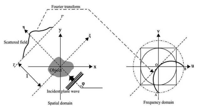
Fig. 1. Fourier diffraction theorem
Ultrasound computerized tomography (UCT) was introduced in [7]-[10]. However, relatively large wavelength associated with typical ultrasound sources result in diffraction of sound wave as it propagates through the object being scanned. Thus, the projections are not line integral. As a result, standard X-ray reconstruction algorithms can not be applied to ultrasound tomography, such as filtered backprojection [11], hence diffraction tomography plays an important roles in ultrasound [12]-[14]. There are two computational strategies for reconstructing the object from its projections. These are interpolation in the frequency domain and interpolation in the space domain [15]. The computational expense of the space domain interpolation of diffracted projections makes frequency domain interpolation more preferable for diffraction tomography reconstruction [16]. In this work, frequency domain interpolation algorithm using B-spline function is introduced.
-
2. Diffraction Tomography
When an object is illuminated with a monochromatic (single wavelength) plane wave, such as ultrasound or microwave, having angle φ with x-axis, and the total field is measured on line TT’, then Fourier transform of the forward scattered field gives values of the arc as shown in Fig. 1.
Suppose that the object is immersed in water medium, and the incident wave is at an angle φ, then the total field u φ is:
ф i , ф s , ф
Where u s,φ is the scattered field, and u i,φ is the incident wave defined as:
ut ( Г ) = Ue - jk 0 S 0° r
Where U 0 is the amplitude of the incident wave. k 0 is the wave number, which equal to 2π/λ, λ is the wavelength.
Our goal is to find a relationship between the scattered field and the object. In order to achieve the above goal, we must solve the inhomogeneous Helmholtz equation:
(v2 + k 2 ) u ( r ) = - k 2o ( r ) u ( r )
To solve the above equation, we take the Born approximation, which assumes that |u s |<<|u i |, [13], [17]. In this case, Fourier transform U s (κ) of the scattered field measured on the line η = l as shown in Fig. 1, is related to the Fourier transform of the object by the following equation, [2].
5 ’ Ф
k 0 U 0 ejj 4k 0 -K 2 ° ™ ( K )
Where O φ (κ) is the Fourier transform of the object evaluated along a semicircle of radius k 0 given by:
f - j k 02 -K 2 + k 0 ) ]
°v(K)= Jo(^’П)e L d^dn
-f
According to (5), it is clear that the rotation of the object from φ = 0 to 2π yields the 2-D Fourier transform of object on disk with radius 2 k . Due to the finite number of the scan angles, the values of O(u, v) can be obtained at some sample points on this disk. In order to reconstruct the object function from these samples, an algorithm based on B-spline interpolation has been proposed.
-
3. Image Reconstruction
In this work, interpolation in the frequency domain is used. It finds the object function from direct 2-D inversion of the frequency domain information. This requires the frequency domain samples to be available on a rectangular grid. However, equation (5) provides the samples over circular arcs. Thus, the data on the rectangular grid is found with interpolating the samples over the arcs. Scanning at angles from 0 to 2π, the arcs AO and OB in Fig. 1 span the same disk independently, i.e. there is double coverage of the frequency domain. The frequency samples for arcs (either AO or OB) are uniform in the parameters (k,φ), whereas their combination would not present a uniform distribution. For interpolation, a relationship between (u,v) and (k,φ) is needed. As arcs AO and OB covers the same points (double coverage), there would be two separate relationships. Let (k 1 ,φ 1 ) and (k 2 ,φ 2 ) denote the points generated by AO and OB, respectively, and convert (u,v) to polar coordinate (w,θ) as:
1 u l w = uu ^ + v ^ ; 0 = tan 11 I (6)
к v ;
From [2], (k 1 ,φ 1 ) is given by:
-
k] = sin(a) ; ^ = 0 +---+ —
And (k 1 ,φ 2 )
k 2 = - sin( a ) ;
a 3n
Ф = 0--+ —
Where a = 2 sin
V 2 k 0 >
The reconstruction algorithm introduced here uses 2-D B-spline interpolation techniques defined as:
MN
Q ( k , Ф ) = У^ Q ( km , Ф п ) B m , k ( k ) B n , k ( ф ) m = 1 n = 1
Where B i,k is the B-spline function of order k, with k = 2 for bilinear interpolation, and k = 4 for bicubic interpolation, as show in the following equations:
B 0,2 = P - 1
1°
for 0 < 1 < 1
for 1 < 1 < 2
And
t 3
B 0,2 =1
-313 +1212 -121 + 4
313 - 2412 + 601 - 44
(4 -1 )3
0 < 1 < 1
1 < 1 < 2
2 < 1 < 3
3 < 1 < 4
-
4. Results and Discussion
-
4.1. Synthetic Phantom
In order to check the feasibility and validity of the proposed algorithm, we apply our method to a synthetic phantom and agar phantom. All algorithms and calculations are implemented under MATLAB.
To evaluate the proposed algorithm, a Shepp-Logan phantom is used [18]. This phantom is a superposition of ellipses as shown in Fig. 2. For simplicity, we assume that we use a monochromatic wave.
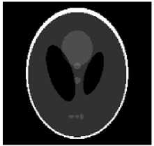
Fig. 2. Shepp-Logan phantom
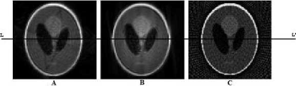
Fig. 3. The reconstructed images for a 128 X 128 Shepp-Logan phantom, with 64 projections: A) Bilinear interpolation, B) Bicubic interpolation, C) Backprojection
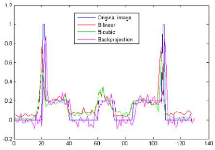
Fig. 4. A cross sectional plot for the images shown in Fig. 3 through the line LL’
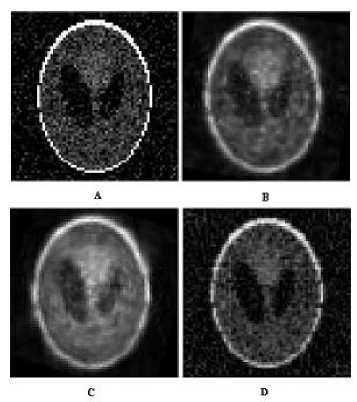
Fig. 5. The effect of the noise on the reconstructed images: A) the noisy image, B) Bilinear interpolation, C) Bicubic interpolation, D) Backprojection
Table 1. Signal to noise ration
|
Method |
SNR |
|
Backprojection |
3.8 |
|
Bilinear Interpolation |
4.9 |
|
Bicubic Interpolation |
5.3 |
Fig. 3 shows the reconstructed images using the proposed algorithm (B-spline bilinear and bicubic interpolations) and the backprojection algorithm too. From Fig. 3, it is clear that our method improves the quality of the reconstructed image. We also examine the effect of the number of projections. Although the backprojection method has better contrast Fig. 3 (C), with same number of projections we found that our method has better spatial resolution.
Fig. 4 shows that the bicubic interpolation gives a fine approximation. Also, we examine the effect of the noise to our method. We consider the object as a noise-contaminated image having a signal to noise ratio (SNR) equal to 2.8 as shown in Fig. 5 (A), and we estimate the SNR for each method as shown in Table 1.
From Table 1, we observe that the Bicubic interpolation have a highest signal to noise ratio.
Also we calculated the absolute error of each method, and we found that, as shown in Fig. 6, bicubic interpolation gives least absolute error.
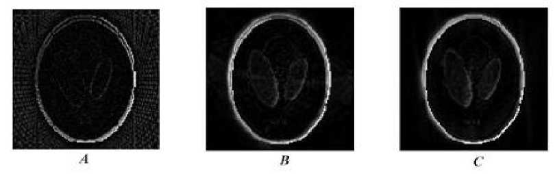
Fig. 6 Absolute Error of each method: A) Bilinear interpolation, B) Bicubic interpolation, C) Backprojection
-
4.2. Agar Phantom
-
5. Conclusion
A 3% agar phantom with 8% glycerol was used to mimic the human tissues. In this experiment we used two agar phantoms, one with olive inside to represent the cancerous tissues, and the other one for the cyst as shown in Fig. 7. Fig. 8 shows the reconstructed images for olive-agar phantom and water-agar phantom.
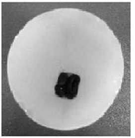
Fig. 7 3% agar phantom with 8% glycerol
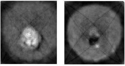
Fig. 8 The reconstructed images for: Left) Olive-agar phantom, Right) water-agar phantom
The interpolation is computed in frequency domain, and the proposed interpolation functions are examined. From the results, we conclude that the bilinear and bicubic interpolation improve the reconstructed image quality and relatively noise independent, as well as they have a better spatial resolution and relatively high SNR. The feasibility was tested using two agar phantoms (water-agar and olive-agar). From the experimental results we conclude that this method is promising in clinical applications. In the future work one can take more realistic situation by taking into consideration that the incident wave (ultrasound wave) is non-monochromatic wave (have more than one wavelength).
Список литературы Diffraction Tomography: It's Application in Ultrasound
- M. Fatemi and A. C. Kak, “Ultrasonic B-scan Imaging: Theory of Image Formation and a Technique for Restoration”. Ultrasonic Imaging. 2, 1– 48, 1980.
- A. Kak and M. Slaney, Principles of Computerized Tomographic Imaging. Philadelphia. PA: SIAM, 2001.
- X. Pan, Unified Reconstruction Theory for Diffraction Tomography, with Consideration of noise Control. J. Opt. Soc. Amer. 15, 2312–2326, 1998.
- X. Pan, Consistency Conditions and Linear Reconstruction Methods in Diffraction Tomography. IEEE Trans. Med. Imag. 19, 51–54, 2000.
- A. Devaney, A Filtered Backpropagation Algorithm for Diffraction Images. Ultrason. Imag. 4, 336–350, 1982.
- R. K. Mueller, M. Kaveh, and G. Wade, Reconstructive Tomography and Applications to Ultrasonics. Proc. IEEE. 67, 567–587, 1979.
- J. F. Greenleaf, S. A. Johnson, S. L. Lee, G. T. Herman, and E. H. Wood, Algebraic Reconstruction of Spatial Distributions of Acoustic Absorption with Tissues from Their Two-Dimensional Acoustic Projections. Acoustical Holography. 5, 591–603, 1974.
- J. F. Greenleaf, S. A. Johnson, W. F. Samayoa, and F. A. Duck, Algebraic Reconstruction of Spatial Distributions of Acoustic Velocities in Tissue from Their Time-of-Flight Profiles. Acoustical Holography. 6, 71–90, 1975.
- J. F. Greenleaf, S. A. Johnson, and A. H. Lent, Measurement of Spatial Distribution of Refractive Index in Tissues by Ultrasonic Computer Assisted Tomography. Ultrasound Med. Biol. 3, 327–339, 1978.
- J. F. Greenleaf and R. C. Bahn, Clinical Imaging with Transmissive Ultrasonic Computerized Tomography. IEEE Trans. Biomed. Eng. BME-28, 177–185, 1981.
- A. C. Kak, Computerized Tomography with X-ray Emission and Ultrasound Sources. Proc. IEEE. 67, 1245–1272, 1979.
- F. Stenger and S. A. Johnson, Ultrasonic Transmission Tomography Based on the Inversion of the Helmholtz Equation for Plane and Spherical Wave Insonification. Appl. Math. Notes. 4, 102–127, 1979.
- K. Iwata and R. Nagata, Calculation of Refractive Index Distribution from Interferograms using Born and Rytov’s approximation. Japan J. Appl. Phys. 14, 1975.
- R. K. Mueller, M. Kaveh, and R. D. Inverson, A New Approach to Acoustic Tomography Using Diffraction Techniques. Acoustical Imaging. 8, 615–628, 1980.
- M. Kaveh, R. K. Mueller, and J. F. Greenleaf, Fourier Domain Reconstruction Methods with Application to Diffraction Tomography. Acoustical Imaging. 13, 17–30, 1984.
- S. X. Pan and Avinash C. KAK, A Computational Study of Reconstruction Algorithms for Diffraction Tomography: Interpolation Versus Filtered Backpropagation. IEEE Transaction On Acoustic, Speech, and Signal Processing. Vol ASSP.31, No.5, 1983.
- A. Ishimaru.: Wave Propagation and Scattering in Random Media. New York: Academic. 2, (1978)
- L. A. Shepp and B. F. Logan.: The Fourier Reconstruction of a Head Section. IEEE Trans. Nucl. Sci. NS-21, 21{43 (1974)
