Distance Protection Settings Based Artificial Neural Network in Presence of TCSR on Electrical Transmission Line

Author: Mohamed Zellagui, Abdelaziz Chaghi
Journal: International Journal of Intelligent Systems and Applications(IJISA) @ijisa
Article in issue: 12 vol.4, 2012.
Free access
This research paper study the performance of distance relays setting based analytic (AM) and artificial neural network (ANN) method for a 400 kV high voltage transmission line in Eastern Algerian transmission networks at Sonelgaz Group compensated by series Flexible AC Transmission System (FACTS) i.e. Thyristor Controlled Series Reactor (TCSR) connected at midpoint of the electrical transmission line. The facts are used for controlling transmission voltage, power flow, reactive power, and damping of power system oscillations in high power transfer levels. This paper studies the effects of TCSR insertion on the total impedance of a transmission line protected by distance relay and the modified setting zone protection in capacitive and inductive boost mode for three zones. Two different techniques have been investigated in order to prevent circuit breaker nuisance tripping to improve the performances of the distance relay protection.
Distance Protection, TCSR, Injected Reactance, Artificial Neural Network
Short address: https://sciup.org/15010348
IDR: 15010348
Text of the scientific article Distance Protection Settings Based Artificial Neural Network in Presence of TCSR on Electrical Transmission Line
Published Online November 2012 in MECS
In recent years, power demand has increased substantially while the expansion of power generation and transmission has been severely limited due to limited resources and environmental restrictions. As a consequence, some transmission lines are heavily loaded and the system stability becomes a power transfer-limiting factor. Flexible AC transmission systems (FACTS) controllers have been mainly used for solving various power system steady state control problems [1].
There are two generations for realization of power electronics based FACTS controllers: the first generation employs conventional thyristor-switched capacitors and reactors, and quadrature tap-changing transformers while the second generation employs gate turn-off (GTO) thyristor-switched converters as voltage source converters (VSCs). The first generation has resulted in the Static Var Compensator (SVC), the Thyristor Controlled Series Capacitor (TCSC), and the Thyristor Controlled Phase Shifter (TCPS) [2-3]. The second generation has produced the Static Synchronous Compensator (STATCOM), the Static Synchronous Series Compensator (SSSC), the Unified Power Flow Controller (UPFC), and the Interline Power Flow Controller (IPFC) [4]. The two groups of FACTS controllers have distinctly different operating and performance characteristics. In the presence of series FACTS devices, the conventional distance relay characteristics such as MHO and Quadrilateral are greatly subjected to mal-operation in the form of overreaching or under-reaching the fault point [5,6]. Therefore, the conventional relay characteristics may not work properly in the presence of FACTS device.
Artificial neural network (ANN) based technology, which is inspired by biological neural networks, has developed rapidly in the previous decade and has been applied in power system protection applications. Specific applications include direction discrimination for protecting transmission lines [7-8], fault classification for faults on double circuit lines [9], ANN based distance relays [10], differential protection of three phase power transformers [11] and faults on generator windings [12], the ANN based designs of generic protection systems proposed so far work well only for ideal fault conditions but do not maintain the integrity of the boundaries of the relay characteristics. Some of the published results related to the application of ANNs in distance protective relaying improvements are stated in the survey given by [13-14]. Reference [15] demonstrates the use of neural networks as a pattern classifier for the distance relaying algorithm and shows that the proposed scheme improves protection system selectivity. In [16] the use of a multilayer feed forward network to reduce the influence of DC offset on fault distance computation is reported. Saturation of current transformers during a heavy fault could cause incorrect distance measurement by the relay.
Performance evaluation of distance protection scheme in presence of FACTS controllers, which affect the apparent impedance calculations at relay point, has been carried out in [17]. The apparent impedance calculations are generally carried out using power frequency components of voltage and current measured at relay point. Some of the published articles dealing with the impact on presence TCSC on distance relay and measured impedance have been reported in references [18-20].
In this paper, the three protection zones setting for a MHO distance relay using two different algorithms i.e. analytic and ANN method are investigated. The investigation concern a 400 kV single transmission line installed at eastern Algerian electrical network. The line is equipped with TCSR series FACTS devices, in capacitive and inductive modes. The performances of the distance relay protection are investigated for different values of firing angle ( α ) with series compensation located in midline electrical transmission.
-
II. Apparent Reactance Injected by Thyristor Controlled Series Reactor (TCSR)
The compensator TCSR mounted on figure 1 consists of variable inductance ( L 1 ) connected in series with the transmission line controlled by thyristors mounted in anti-parallel and controlled by an firing angle ( α ) which varies between 90° and 180°, and a fixed value inductance ( L 2 ) connected in shunt [1-2].
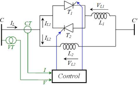
Fig. 1: Principal operation of TCSR
This compensator can be modeled as a variable reactance ( XTCSR ) as shows in figure 2.
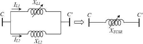
Fig. 2: Apparent reactance injected by TCSR
From figure 2, the total reactance of the TCSR is defined by the following formula [1-4]:
X tcsr ( a ) = X l , ( a )// X l 2 = X L, ' ( “ ). X L 2
X L ( a ) + XL 2
The reactance of the first inductance XL1 ( α ) controlled by thyristors is defined by formula:
П
L 1 - max \
л - 2a - sin(2a)
Where,
= L .ю
L 1 - max
And the second reactance of inductance (XL2) is defined by formula:
XL 2 = L2 .ю
From formula (2) and (4), the final formula (1) becomes:
L^L ^2
X I-CSR ( a )
v n - 2 a - sin(2 a )
ю l2 + l
л:
л - 2 a - sln(2 a )
-
III. Distance Protection in Electrical Transmission Line
Distance protection is so called because it is based on an electrical measure of distance along a transmission line to a fault. The distance along the transmission line is directly proportional to the series electrical impedance of the transmission line ( ZL ). Impedance is defined as the ratio of voltage to current [21-23]. The philosophy of setting relay at Sonelgaz Group [24] is three zones forward ( Z 1 , Z 2 and Z 3 ) for protection the transmission line HV between busbar A and B with total impedance Z AB as shown in figure 3.
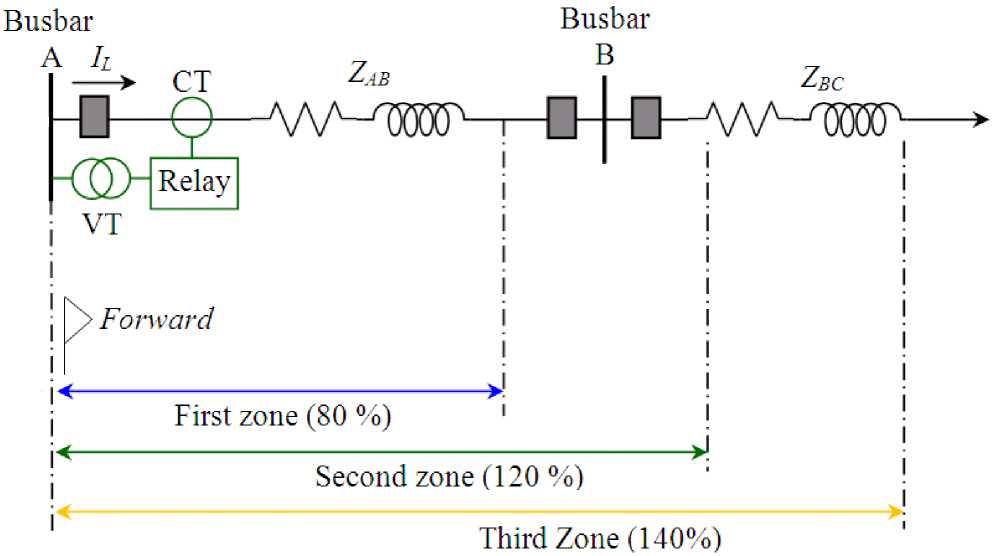
Fig. 3: Setting zones for distance protection
The setting zones for protected transmission line without TCSR system are expressed by [22-23]:
Z1 = Rx + jX1 = 80% Zab = 0,8.( Rab + jXAB)
Z2 = R 2 + jX2 = Rab + jXAB + 0,2.( Rbc + jXBc )
Zз = Rз + jXз = Rab + jXAB + 0,4.(Rbc + jXBC)
The total impedance of electrical transmission line AB measured by distance relay is:
Z. = = Kz . Z, AB Z L


Where,
K VT

jX
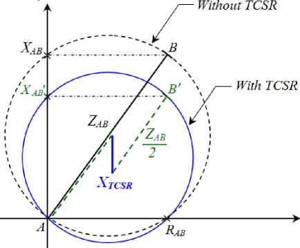
Fig. 4: Impact of presence TCSR on total impedance Z AB for distance protection
From figure 4, the setting zones for protected transmission line with TCSR connected at midline are:
And,
kct

The impedance Z AB is real total impedance of transmission line AB, and K VT and K CT is ratio of voltage to current respectively. The presence of TCSR compensator ( X TCSR ) has a direct influence on the total impedance of the protected line ( Z AB ). This effect especially on the reactance XAB and no influence on the resistance RAB , it is represented in figure 4.
Z2 Z ZABZ ^± Xtcsr (a) + ZAV, + 0,2. Zbc
Vх) (13)
Z з = f AZ1 ^± X tcsR ( a )+ AZ1 + 0,4. Z bc
V } (14)
-
IV. Application ANN on Power Systems
The multilayer perception neural network is built up of simple components. We will begin with a singleinput neuron, which we will then extend to multiple inputs. We will next stack these neurons together to produce layers.
Finally, we will cascade the layers together to form the network. A single-input neuron is shown in figure 5. The scalar input ( p ) is multiplied by the scalar weight ( w ) to form ( wp ), one of the term that is sent to the summer. The other input 1 is multiplied by a bias ( b ) and then passed to the summer. The summer output ( n ), often referred to as the net input goes into a transfer function ( f ), which produces the scalar neuron output ( a ) [25-26].
Fig. 5: Single input neuron
Note that and are both adjustable scalar parameters of the neuron. Typically the transfer function is chosen by the designer, and then the parameters w and b are adjusted by some learning rule so that the neuron input/output relationship meets some specific goal.
The transfer function may be a linear or a nonlinear function of n . One of the most commonly used functions is the log-sigmoid transfer function, which is shown in figure 6.
Fig. 6: Log-Sigmoid transfer function
This transfer function takes the input (which may have any value between plus and minus infinity) and squashes the output into the range 0 to 1, according to the formula:
a =
1 + e "n
The log-sigmoid transfer function is commonly used in multilayer networks that are trained using the back propagation algorithm, in part because this function is differentiable.
-
4.1. Multiple Inputs and Output
Typically, a neuron has more than one input. A neuron with R inputs is shown in figure 7. The individual inputs p 1 , p 2 … p R are each weighted by corresponding elements w 1 , w 2 … w R of the weight matrix ( W ).
Fig. 7: Multiple Input Neurons
The neuron has a bias b , which is summed with the weighted inputs to form the net input n :
n = wt p px + w ^ 2. p 2 + ... + w R. pR + b
Where the matrix W for the single neuron case has only one row. Now the neuron output can be written as:
a = f (W . p + b )
Figure 8 represents the neuron in matrix form.
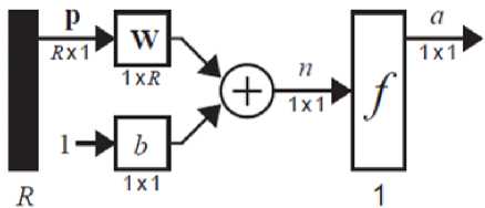
Fig. 8: ANN structure with R inputs
Commonly one neuron, even with many inputs S , is not sufficient. We might need five or ten, operating in parallel, in what is called a layer. A single-layer network of neurons is shown in figure 9. Note that each of the R inputs is connected to each of the neurons and that the weight matrix now has S rows.
The layer includes the weight matrix W , the summers, the bias vector a , the transfer function boxes and the output vector b . Some authors refer to the inputs as another layer, but we will not do that here. It is common for the number of inputs to a layer to be different from the number of neurons (i.e., R≠ S ) [26].
The S neuron, R input, one-layer network also can be drawn in matrix notation, as shown in figure 9.
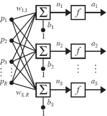
Fig. 9: ANN structure with Layer of S neurons
-
4.2. Multiple Layers of Neurons
Now consider a network with several layers. Each layer has its own weight matrix W , its own bias vector b , a net input vector n and an output vector a .
We need to introduce some additional notation to distinguish between these layers. We will use superscripts to identify the layers. Thus, the weight matrix for the first layer is written as W1 , and the weight matrix for the second layer is written as W2 . This notation is used in the three-layer network shown in figure 8. As shown, there are R inputs, S1 neurons in the first layer, S2 neurons in the second layer, etc. As noted, different layers can have different numbers of neurons.
The outputs of layers one and two are the inputs for layers two and three. Thus layer 2 can be viewed as a one-layer network with R = S1 inputs S2 = S1 neurons, and an S2 × S1 weight matrix W2 .
The input to layer 2 is a1, and the output is a2. A layer whose output is the network output is called an output layer . The other layers are called hidden layers . The network shown in figure 10 has an output layer (layer 3) and two hidden layers (layers 1 and 2).
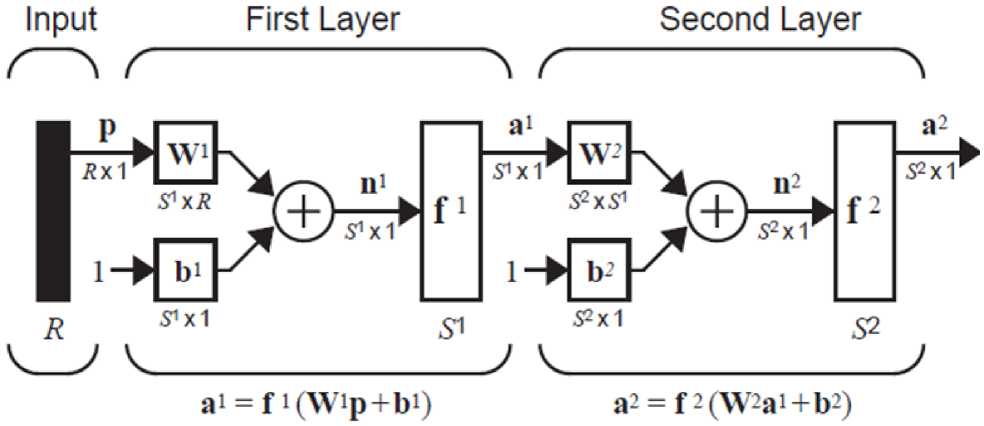
Fig. 10: ANN structure with two layer
-
4.3. Application on Power System
The electric power industry is currently undergoing an unprecedented reform. One of the most exciting and potentially profitable recent developments is increasing usage of ANN techniques. A major advantage of ANN approach is that the domain knowledge is distributed in the neurons and information processing is carried out in parallel-distributed manner [26].
Being adaptive units, they are able to learn these complex relationships even when no functional model exists. This provides the capability to do ‘Black Box Modeling’ with little or no prior knowledge of the function itself. ANNs have the ability to properly classify a highly non-linear relationship and once trained, they can classify new data much faster than it would be possible by solving the model analytically.
The rising interest in ANNs is largely due to the emergence of powerful new methods as well as to the availability of computational power suitable for simulation. The field is particularly exciting today because ANN algorithms and architectures can be implemented in VLSI technology for real-time applications. The application of ANNs in many areas under electrical power systems has lead to acceptable results.
-
V. Case Study and Simulation Results
The figure below represents the 400 kV, 50 Hz power system eastern Algerian electrical transmission networks at Sonelgaz group (Algerian Company of Electricity and Gas) studied in this paper [24]. The distance relay is located in the busbar A at Ain M’lila substation to protect transmission line between busbar A and busbar B at Batna substation, the bus bar C is located at Biskra substation.
The series FACTS study type TCSR is installed in the midpoint of the electrical line protected by a distance relay. The parameters of line and TCSR installed are summarized in the appendix.
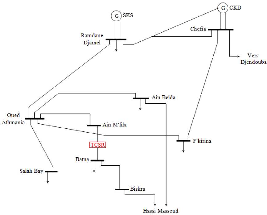
Fig. 11: Electrical networks 400 kV study in presence TCSR
The characteristic curve X TCSR ( α ) of the TCSR used in this case study is shown in figure 12.
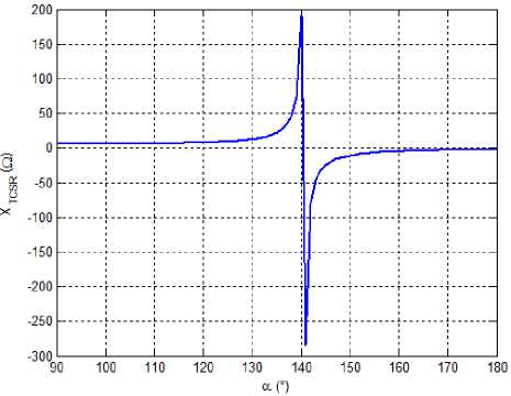
Fig. 12: Characteristic curve of TCSR installed
-
5.1. Setting relay without TCSR
The total impedance measured by the distance relay without series FACTS is: Z L = 2.4039 + j 23. 2432 Ω . The settings zones are summered in table 1.
Table 1: Setting distance protection without TCSR
|
Setting zones |
Values |
|
|
X 1 (О) |
R i (О) |
|
|
Z 1 |
1,1157 |
0,1154 |
|
Z 2 |
1,8493 |
0,1913 |
|
Z 3 |
2,3039 |
0,2383 |
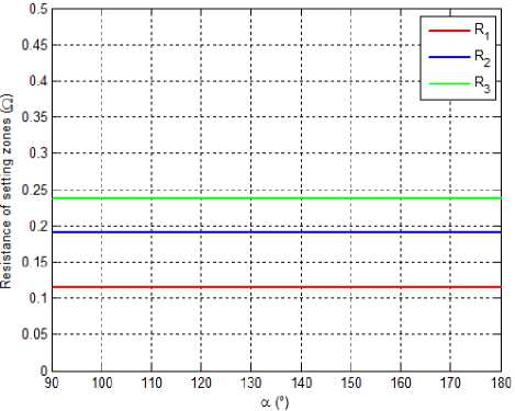
(b)
Fig. 13: Parameters of setting zones in variation angle α (a). Reactance, (b). Resistance.
Figures 13.a and 13.b represented the impact of the angle variation α on the settings zones reactance and resistance respectively for transmission line based analytical method.
5.2. Setting relay on presence TCSR based AM method
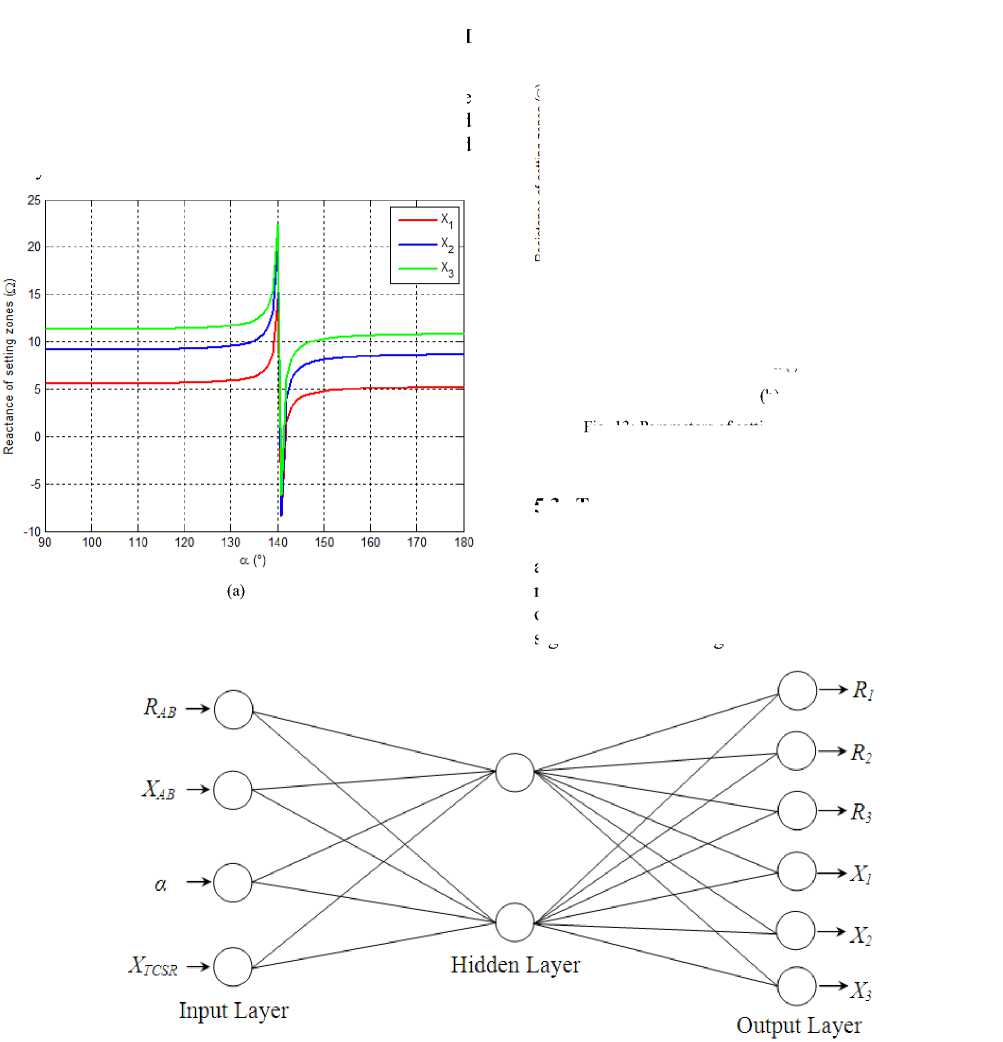
Fig. 14: Structure ANN proposed for setting zones
-
5.3. Topology of ANN Proposed
One of the keys to the success of any ANN application is the choice of input signals. In this case measured impedance (i.e.: R AB and X AB ) and change rate of reactance XTCSR and firing angle α are taken as input signals as shown in figure 14.
In block pre-processing is calculate the inputs parameters for ANN by this relations:
X
GCSC

Zab = Rab + j • Xab

We will use the networks of neurons with training supervised especially of the multi-layer networks, pulled by the algorithm of back propagation which remains more used.
The algorithm of Levenberg-Marquardt has a good robustness for the diagnosis by networks of neurons and seems to be most effective according to the researchers in this field. The architecture of the ANN is a significant factor deciding on the quality of the training more than the parameters of training.
The block diagram of the proposed ANN based setting protection for three zones ( R 1 , R 2 , R 3 , X 1 , X 2 and X 3 ) at outputs for MHO distance relay scheme as indicated in figure 15.
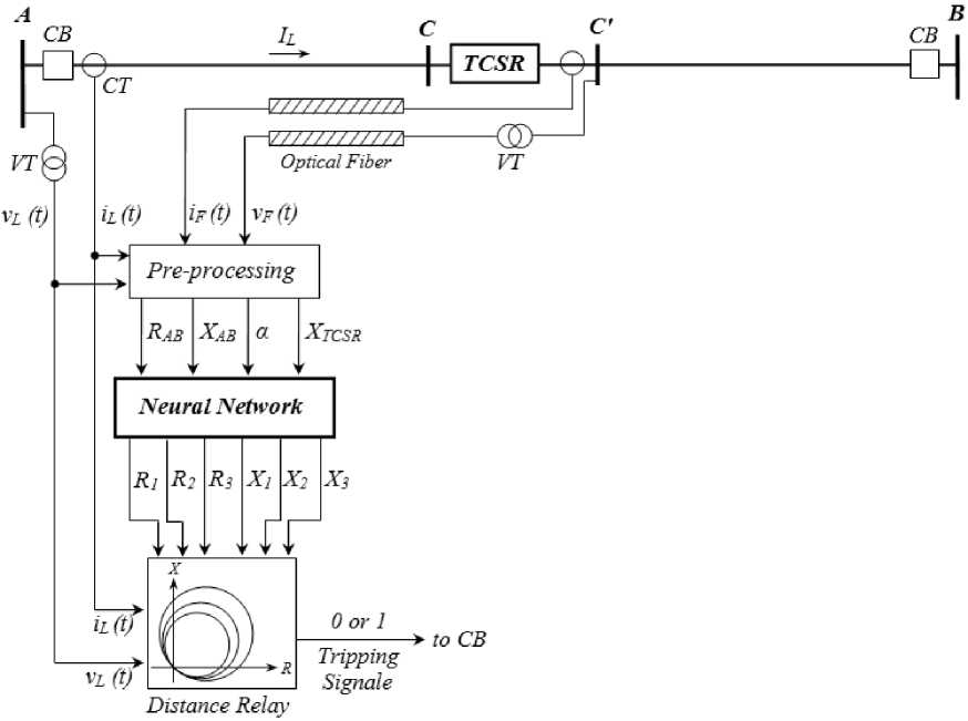
Fig. 15: Topology of MHO distance relay based ANN
The parameters for ANN are summered in table 2.
Table 2: Neural networks specifications
|
Parameters |
Values |
|
Number of input neurons |
4 |
|
Number of output neurons |
6 |
|
Number of hidden layers |
1 |
|
Number of neurons of hidden |
8 |
|
Stimulating of hidden neurons |
Hyperbolic Tangent |
|
Stimulating of output neurons |
Sigmoid |
|
Training algorithm |
Levenberg Marquardt |
-
5.4. Setting relay on presence TCSR based ANN
The resultants of testing data of ANN algorithm proposed for calculation setting distance relay on two boost modes, inductive in Table3 and capacitive in Table 4, with the percentage error ( ε ) between the accurate value based AM and the estimated based ANN one where:
Table 3: Relay setting in the inductive boost mode
|
Setting zones |
Firing angle (°) |
|||||
|
90 |
100 |
120 |
130 |
140 |
||
|
X TCSR (O) |
6,0500 |
6,1048 |
7,8640 |
12,706 9 |
191,00 8 |
|
|
R ab (O) |
2,4039 |
2,4039 |
2,4039 |
2,4039 |
2,4039 |
|
|
X ab (O) |
116,46 |
116,52 |
118,28 |
123,12 |
301,42 |
|
|
Z 1 |
X i (O) |
5,5141 |
5,4322 |
5,5441 |
5,8243 |
14,331 |
|
R 1 (O) |
0,1154 |
0,1154 |
0,1154 |
0,1154 |
0,1154 |
|
|
ε r (%) |
1,361 |
2,871 |
2,346 |
1,445 |
0,942 |
|
|
Z 2 |
X 2 (O) |
9,0822 |
9,112 |
9,1443 |
9,4355 |
20,100 |
|
R 2 (O) |
0,1913 |
0,1913 |
0,1913 |
0,1913 |
0,1913 |
|
|
ε r (%) |
0,715 |
0,425 |
1,211 |
1,167 |
0,716 |
|
|
Z 3 |
X 3 (O) |
11,115 |
11,146 |
11,290 |
11,623 |
22,130 |
|
R 3 (O) |
0,2383 |
0,2383 |
0,2383 |
0,2383 |
0,2383 |
|
|
ε r (%) |
1,701 |
1,456 |
1,106 |
0,716 |
1,227 |
|
Table 4: Relay setting in the capacitive boost mode
|
Setting zones |
Firing angle (°) |
|||||
|
145 |
155 |
165 |
175 |
180 |
||
|
X TCSR ( O ) |
-24,396 |
-6,6227 |
-3,5657 |
-2,3663 |
-2,0167 |
|
|
R ab (O) |
2,4039 |
2,4039 |
2,4039 |
2,4039 |
2,4039 |
|
|
X AB (O) |
86,0164 |
103,79 |
106,85 |
108,05 |
108,40 |
|
|
Z 1 |
X 1 (O) |
4,0525 |
4,7947 |
5,1132 |
5,1528 |
5,1121 |
|
R 1 (O) |
0,1154 |
0,1154 |
0,1154 |
0,1154 |
0,1154 |
|
|
ε r (%) |
1,847 |
3,757 |
0,300 |
0,644 |
1,747 |
|
|
Z 2 |
X 2 (O) |
7,2822 |
8,3575 |
8,5343 |
8,6102 |
8,6303 |
|
R 2 (O) |
0,1913 |
0,1913 |
0,1913 |
0,1913 |
0,1913 |
|
|
ε r (%) |
0,527 |
0,354 |
0,424 |
0,374 |
0,384 |
|
|
Z 3 |
X 3 (O) |
9,3211 |
10,1972 |
10,5611 |
10,7584 |
10,7701 |
|
R 3 (O) |
0,2383 |
0,2383 |
0,2383 |
0,2383 |
0,2383 |
|
|
ε r (%) |
1,683 |
3,317 |
1,578 |
0,408 |
0,492 |
|
-
VI. Conclusion
Neural networks could be used as a part of a new generation of high speed advanced protection relays. It results in a more reliable distance scheme for transmission line protection. ANN as control technique was used to be implemented in distance relay. New setting zones for distance relay relaying technique based on ANN technique have been developed. The relay has been tested for different value of firing angle for different boost modes. In all these test cases, the maximum error was found to be less than 4%. The proposed relaying technique has the ability to provide accurate and vigorous estimation for the variation of TCSR installed on 400 kV electrical transmission line.
The authors would like to thank the anonymous reviewers for their careful reading of this paper and for their helpful comments.
ZL = 0,03293 + j 0,3184 Ω/km, lAB = 73 km, lBC = 119 km.
Q L1-max = 20 MVar,
L 2 = 0,0193 H,
Q L2-max = 80 MVar.
I sec = 5 A,
K CT = 240.
-
4. Voltage Transformer
V pri = 400000 / √3 V,
V sec = 100 / √3 V,
K CT = 4000.
Mr. Mohamed ZELLAGUI was born on October 01, 1984 in Constantine, Algeria. He received the engineer and MS degree in Electrical Engineering (Electrical Networks) from department of Electrical Engineering at University of Constantine, Algeria in 2007 and 2010 respectively. Doctorate Student and member LSP-IE research laboratory from department of Electrical Engineering at Batna University, Algeria. He is Electrical Engineer in Group Sonelgaz (Algeria Company of Electrical and Gas), Member at International Association of Engineers (IAENG), and the Institution of Engineering and Technology (IET). He has authored over 15 international journal articles and book as well as over 10 international conference papers. His areas of interest include power system protection, distance relay, neural network, and FACTS devices.
Pr. Abdelaziz CHAGHI was born in Batna, Algeria, 1954. He received his BS degree from the University of Oran, Algeria in 1980, and Master from the Manchester University, England in 1984, and received his PhD on electrical engineering from University of Batna, Algeria in 2004. He is currently a Professor at the department of Electrical Engineering in the Faculty of Technology, and member in the LSP-IE research laboratory at University of Batna. He has authored over 20 international journal articles and book as well as over many international conference papers. His areas of interest include power systems, distance relay, power quality, neural network, power electronics and FACTS devices.
References Distance Protection Settings Based Artificial Neural Network in Presence of TCSR on Electrical Transmission Line
- K.K. Sen, M.L. Sen, Introduction to FACTS Controllers: Theory, Modeling and Applications, Published by John Wiley & Sons, Inc., and IEEE, New Jersey, USA, July 2009.
- X.P. Zhang, C. Rehtanz, B. Pal, Flexible AC Transmission Systems: Modelling and Control, Published by Springer Publishers, Heidelberg, Germany, June 2006.
- E. Acha, C.R. Fuerte-Esquivel, H. Ambriz-Pérez, C. Angeles-Camacho, FACTS Modelling and Simulation in Power Networks, Published by John Wiley & Sons Ltd Publication, London, England, April 2004.
- R.M. Mathur, R.K. Varma, Thyristor-Based FACTS Controllers for Electrical Transmission Systems, Published by John Wiley & Sons, Inc. Publication ant IEEE Press, New York, USA, June 2002.
- P.K. Dash, A.K. Pradhan, G. Panda, Apparent Impedance Calculations for Distance Protected Transmission Lines Employing Series-Connected FACTS Devices, Electric Power Components and Systems, Vol. 29, No. 7, July 2001, pp. 577-595.
- P.K. Dash, A.K. Pradhan, G. Panda, A.C. Liew, Digital Protection Of Power Transmission Lines in The Presence Of Series Connected FACTS Devices, Proceedings of IEEE/PES Summer Meeting, Washington, USA, 19 July, 2000, pp. 1967-1972.
- H. Singh, M.S. Sachdev, T.S. Sidhu, Design, Implementation and Testing of an Artificial Neural Network Based Fault Direction Discriminator for protecting Transmission Lines, IEEE Transactions on Power Delivery, Vol. 10, No. 2, April 1995, pp 697-706.
- A.L.O Fernandez, N.K.I Ghonaim, A Novel Approach using a FIRANN for Fault Detection and Direction Estimation for High Voltage Transmission Lines, IEEE Transactions on Power Delivery, Vol. 17, No. 4, October 2002, pp 894-900.
- A. Bennett, A.T. Johns, Q.Y. Xuann, R.K Aggarwal, R.W. Dunn, A Novel Classification Technique for Double-circuit lines Based on Combined Unsupervised/Supervised Neural Network, IEEE Transactions on Power Delivery, Vol. 14, No. 4, August 1999, pp 1250-1255.
- B. Balamurugan, R. Venkatesan, A Real-Time Hardware Fault Detector Using an Artificial Neural Network for Distance Protection, IEEE Transactions on Power Delivery, Vol.16, No. 1, January 2001, pp 75-82.
- A.L. Orille-Fernandez, J.A. Valencia, N.K.I. Ghonaim, A FIRANN as a Differential Relay for Three Phase Power Transformer Protection, IEEE Transactions on Power Delivery, Vol. 16, No. 2, April 2001, pp 215-218.
- A.M.I. Talaab, H.A. Darwish, T.A. Kawady, Development and Implementation of an ANN-Based Fault Diagnosis Scheme for Generator Winding Protection, IEEE Transactions on Power Delivery, Vol. 16, No. 2, April 2001, pp 208-214.
- P.S. Bhowmik, P. Purkait, K. Bhattacharyya, Proposal for a Distance Relaying Scheme based on Wavelet Assisted Neural Network, Proceedings of IEEE/PES Conversion and Delivery of Electrical Energy in the 21st Century, Pittsburgh, USA, 20-24 July 2008.
- H.K. Zadeh, Z. Li, An ANN Based Approach to Improve the Distance Relaying Algorithm, Turkish Journal of Electrical Engineering & Computer Sciences, Vol. 14, No. 2, February 2006, pp. 345-35.
- D.V. Coury, D.C. Jorge, Artificial Neural Network Approach to Distance Protection, IEEE Transaction on Power Delivery, Vol. 13, No. 1, January 1998, pp. 102-108.
- S.H. Kang, K.H. Kim, K.R. Cho, J.K. Park, High Speed offset Free Distance Relaying Algorithm using Multilayer Feed forward Neural Networks, Proceedings of International Conference on Intelligent Systems Applications to Power Systems (ISAP’ 1996), Orlando, USA, 8 Jan.-2 Feb., 1996.
- P.K. Dash, A.K. Pradhan, G. Panda, A.C. Liew, Adaptive Relay Setting for Flexible AC Transmission Systems (FACTS), IEEE Transaction on Power Delivery, Vol. 15, No. 1, 2000, pp. 38-43.
- P.S. Chaudhari, P.P. Kulkarni, R.M. Holmukhe, P.A. Kulkarni, TCSC for Protection of Transmission Line, Proceedings of 3rd International Conference on Emerging Trends in Engineering and Technology (ICETET’2010), Goa, India, 19-21 November 2010.
- A. Shojaei, S.M. Madani, Analysis of Measured Impedance by Distance Relay in Presence of SSSC, Proceedings of 5th IET International Conference on Power Electronics, Machines and Drives (PEMD’2010), Brighton, UK, 19-21 April 2010.
- S. Jamali, H. Shateri, Locus of Apparent Impedance of Distance Protection in the Presence of SSSC, European Transactions on Electrical Power, Vol. 21, No.1, January 2011, pp. 398-412.
- G. Zigler, Numerical Distance Protection: Principles and Applications, Third Edition, published by Publics Corporate Publishing, Germany, 2008.
- M. Zellagui, A. Chaghi, Distance Protection for Electrical Transmission Line: Equipments, Settings Zones and Tele-Protection, published by LAP Lambert Academic Publishing, Germany, June 2012.
- J.L. Blackburn, T.J. Domin, Protective Relaying: Principles and Applications, Third Edition, Published by CRC Press and Taylor & Francis Group, USA, February 2006.
- N. Manamani, Principles and Settings of Distance Relay, Group Sonelgaz, Training at GRTE Sétif, Group Sonelgaz, Algeria, 15 June 2009.
- L.R. Medsker, L.C. Jain, Recurrent Neural Networks Design and Applications, published by CRC press, Washington, USA, March 2001.
- G. Dreyfus, Neural Networks: Methodology and Applications published by Springer-Verlag, Berlin, Germany, 2005.
