Distributed reaction surface of carbon-graphite volume-porous cathodes as a parameter for optimizing of metallization process of composite and nanocomposite materials

Author: Koshev A.N., Kuzina V.V.
Journal: Nanotechnologies in Construction: A Scientific Internet-Journal @nanobuild-en
Section: Construction materials science
Article in issue: 2 Vol.17, 2025.
Free access
Introduction. The porous composite and nanocomposite materials discussed in this publication are metallized carbon-graphite materials, in particular carbon fiber materials (CFMs). At metallization of CFMs one of the actual problems is the task of applying uniform metal coating on the surface of CFMs fibers over the entire volume of the processed material. One of the most effective ways to coat CFMs with metals and their alloys is the galvanic method. This method allows, among other things, to optimize the process by optimizing both the design of the electrolyzer with flow-through three-dimensional electrodes (FTE) and the choice of electrodeposition modes, such as galvanic, concentration, and hydrodynamic. Materials and methods. Methods of mathematical modeling of porous medium metallization processes and previously published experimental data were used to solve problems on calculation of operating modes and elements of the electrolyzer design, in particular, the specific reaction surface of the UWM distributed over the thickness of the electrolyzer. Results and discussion. The development of mathematical models of the processes of electroplating metallization of CFMs is carried out. Boundary value problems of mathematical physics are formulated and calculation methods are proposed. Problems of optimization of distribution of specific reaction surface of CFMs by thickness of FTE on the basis of electrochemical theory of processes in porous medium are set, ways of their solution are presented. Specific technological problems are solved. The comparison of the most effective values of the distribution of specific reaction surface of CFMs over the thickness of FTE obtained as a result of modeling with the experimental data is given. The workability of models and methods for studying the process of copper electrodeposition from sulfuric acid electrolyte is shown. Conclusion. Calculation of regularities of electrochemical processes of metal extraction in FTE on the basis of the developed mathematical models allows to predict the results of electrolysis, determine the optimal modes of operation and elements of FTE design. The use of FTE for metallization of CFMs with properly distributed reaction surface contributes to obtaining composite materials with specified properties.
Carbon-graphite cathode, composite and nanocomposite materials, metallization process, distributed reaction surface, mathematical modeling, optimization
Short address: https://sciup.org/142243951
IDR: 142243951 | DOI: 10.15828/2075-8545-2025-17-2-119-131
Text of the scientific article Distributed reaction surface of carbon-graphite volume-porous cathodes as a parameter for optimizing of metallization process of composite and nanocomposite materials
Original article
Кошев А.Н., Кузина В.В. Распределенная реакционная поверхность углеграфитовых объемно пористых катодов как параметр оптимизации процесса металлизации композиционных и нанокомпозиционных материалов. Нанотехнологии в строительстве. 2025;17(2):119–131. – EDN: XWDYCA.
In various fields of industrial production of high-tech products [1–9], composite materials of carbon fiber materials (CFMs) with metallic coating of carbon graphite filaments with gold, silver, platinum, copper or other metals and their alloys selected to ensure the given technological requirements are used.
Metal coating on CFMs is possible by various methods, both chemical and mechanical, but the most effective method of metallization of a solid porous base appears to be metallization using electrolysis methods [10–14]. Galvanic metallization of CFMs is preferable for a number of reasons, the main of which, of course, is the possibility of selecting the mode of electrodeposition: the strength of the overall current, the speed and direction
CONSTRUCTION MATERIALS SCIENCE of the electrolyte flow, the concentration of electroactive substances, the design features of the electrolyzer and other technological conditions. The choice of modes of electrolysis, shape and material of the cathode, as well as the composition and concentration of the electrolyte is determined by the requirements to the technical parameters of the composite material and technological parameters of the electrodeposition process, which, first of all, include such as the uniformity of metal distribution over the thickness of the CFMs and the intensity of the deposition process.
Optimization of electrodeposition modes and design features of the electrolyzer in order to intensify metallization and obtain materials with specified properties is impossible without the use of methods of mathematical modeling and calculation of regularities of electrochemical processes and prediction of electrolysis results [13]. One of the main characteristics that provide a significant intensification of metal electrodeposition on the CFMs in a flowing three-dimensional electrode (FTE) is the value of the specific reaction surface of the electrode.
Electrolysis of metals in electrolyzers with FTE is carried out, as a rule, from dilute solutions. This allows to
use the advantages of CFMs cathodes, such as the ability to conduct processes with a high deposition rate and a sufficient degree of filling of the electrode with metal. The process of CFMs metallization is limited by the diffusion of ions to the surface of fibers. The thickness of the diffusion layer limiting the discharge rate of metal ions for 10 µm diameter fibers is assumed to be 10–4 cm [14].
Obviously, when determining the specific reaction surface of the CFMs, not only the total lateral surface of the carbon-graphite fibers, but also those surface roughnesses (protrusions, depressions, etc.), the size of which in their defining heights and depths is not less than the thickness of the diffusion layer, i.e., a value of the order of 10–4 cm, should be taken into account.
The papers [14, 15] present the results of studies conducted by Prof. V.K. Varentsov and co-workers to determine the value of S v – the reaction surface of CFMs during electrodeposition of metals in FTE limited by the diffusion stage of the galvanic process.
Table 1 contains values of some nonwoven and woven CFMs parameters: r – fiber radius, S v – specific surface determined by electrochemical method, κ – specific electrical conductivity of CFMs in free and compressed
Table 1. Parameters of carbon fiber materials
|
Materials |
r , μm |
Sv , cm–1 |
κ, Siemens/cm |
ε |
|
VNG-50 |
6.0 |
265 |
1.3/2.6 |
0.92 |
|
VNG-30 |
5.5 |
160 |
0.90/0.33 |
0.96 |
|
VINN-250 |
4.5 |
280 |
0.1/0.4 |
0.97 |
|
NTM-200 |
5.0 |
216 |
0.07/0.4 |
0.96 |
|
NTM-100 |
5.4 |
220 |
0.03/0.12 |
0.96 |
|
Mtilon |
5.1 |
270 |
0.13/0.5 |
0.94 |
|
VVP-66-95 |
4.7 |
255 |
0.006/0.05 |
0.96 |
|
FPN |
5.0 |
125 |
0.001/0.005 |
0.98 |
|
KNM |
6.1 |
160 |
0.009/0.03 |
0.98 |
|
VINN-150 |
5.0 |
220 |
0.05/0.16 |
0.92 |
|
KSS |
4.5 |
– |
0.1/0.2 |
0.89 |
|
Uglen |
5.1 |
240 |
0.05/0.13 |
0.95 |
|
Gralen |
4.9 |
260 |
0.1/0.4 |
0.96 |
|
NT-1 |
6.2 |
165 |
0.001/0.02 |
0.90 |
|
NT-2 |
6.2 |
165 |
0.003/0.014 |
0.90 |
|
AMN |
6.1 |
180 |
0.01/0.12 |
0.96 |
|
TVSh |
4.6 |
780 |
0.16/0.4 |
0.91 |
|
TGN-2M |
5.0 |
220 |
0.45/1.5 |
0.85 |
|
LVIK-95 |
6.0 |
270 |
0.26/0.87 |
0.83 |
|
LG-50 |
3.8 |
150 |
0.02/0.09 |
0.76 |
|
LG-30 |
3.7 |
180 |
0.64/2.1 |
0.78 |
|
LG-10 |
3.4 |
170 |
0.44/1.4 |
0.77 |
CONSTRUCTION MATERIALS SCIENCE twice (above the line and below the line, respectively), ε – porosity of CFMs [14].
The results of studies conducted by V.K. Varentsov and co-workers and presented in [14] allow us to state that nonwoven CFMs have a significantly larger surface area of carbon-graphite fibers, on which electrochemical reactions are possible, compared to woven CFMs.
Our statistical processing of the data from Table 1 shows that the most significant factors influencing the value of specific reaction surface S v are fiber radius r and material porosity ε:
S v = a 0 + a r r + a εε + a r ε r ε. (1)
Based on the calculations performed, the coefficients of the regression model a 0, a r , a ε , a r ε , were determined, and it was shown that the a r ε r ε summand in relation (1) is much less significant in comparison with the first and second summands. Consequently, the dependence of the reaction surface S v as a function of the parameters a 0, a r , a ε can be assumed linear:
S v = 3066,93 – 574,911 r + 24,567ε. (2)
The constructed model can be used to estimate the specific surface if the fiber radius and porosity of the CFMS are known; it should be noted that they are obtained for 4.5 ≤ r ≤ 6.1 (µm) and 92 ≤ ε ≤ 98%, so they cannot be extrapolated for r and ε, which strongly exceed the boundaries of these intervals. For the same reason, they may be of little use for determining the specific surface area of FTE during metal electrodeposition, inside a porous space, when r and ε change significantly.
In the case when the radius of the CFMs fiber, the porosity of the material and, as a consequence, its specific reaction surface change significantly in the process of metal deposition, it is necessary to take into account these changes in the mathematical modeling of the electrolysis process.
To find the dependence of the specific surface area of the CFMs S v on the weight of the metal precipitate M , in the first approximation, it was considered that the precipitate is distributed along the fibers uniformly. With the known porosity of the material, it is possible to find the volume of fibers that make up a “tablet” of CFMs with an area of 1 cm2 and a thickness of 1 cm, and determine n – the number of fibers in the tablet, assuming that each of the fibers represents a cylinder of known radius r : n = (1 – ε)/(π r 2).
When M grams of metal with density q, g/cm3 are deposited, the radius of the fibers and the porosity of the electrode become equal to respectively гm = J产+詣'…£М = £ —9, (3)
and specific surface
Sv = 2u = 『 /^^ . (4)
Let us show the magnitude of change of specific reaction surface from the amount of deposited metal for r = 5·10–4 cm, ε = 0.95. For these values we can take n ≈ 6·104. At the beginning of the process r M = r , and from formula (3) we find S v = 200 cm. Let us find S v max when the maximum amount of metal achieved in practice is deposited on the FTE. For gold, this is approximately M = 40 g per 1 g of CFMs. Considering the density of carbon graphite equal to 1.6 g/cm3 [16], it is easy to determine that 3.2 g of metal can be deposited on the considered volume of CFMS. For gold q = 19.6 g/cm3. Substituting these data into (3), we find S v max ≈ 413 cm3. Thus it is determined that in this case there can be a doubling of the specific surface of FTE for the whole cycle of metal deposition from the solution. It is obvious that when solving problems on determination of technological parameters of metal extraction process on FTE it is necessary to take into account possible changes of values of specific surface, porosity, linear velocity of electrolyte flow, etc. in the dynamics of electrolysis.
To calculate the specific reaction surface S v by equation (4), we use the following reasoning. The amount of deposited metal – ∆ M during the FTE operation time – ∆τ, at the electrode point – x , 0 ≤ x ≤ L , in the FTE cross-section, with an area equal to one, will be determined by the ratio: ∆ M = [ M ( x ,τ + ∆τ) – M ( x ,τ)]∆ x ; the concentration of the deposited metal ions during the flow of the electrolyte solution from point x to point x + ∆ x will decrease by the amount ∆ C = [ C ( x ,τ) – C ( x + ∆ x ,τ)]; the concentration of metal ions per unit time will change by the value – ∆ Cm v , and the amount of metal deposited in a unit section of FTE at point x with thickness ∆ x , therefore, will be equal to ∆ Cm v ∆τ.
From the obvious relation [ M ( x ,τ + ∆τ) – M ( x ,τ)] ∆ x = ∆ Cm v ∆τ, in the limit at ∆ x → 0 and ∆τ → 0, it is not difficult to obtain the formula
M ( x ,τ) = m v dx ∫0τ (∂ C ( x , t )/∂ x ) dt .
M ( x ,τ) – the amount of metal at point x during time τ – will be used in the calculation of specific surface S v ( x ,τ) by formula (4).
The presented information allows us to conclude that the specific reaction surface of FTE should be considered as one of the parameters to be optimized. Moreover, the possibility to select materials for FTE formation (see Table 1) allows us to consider cathodes with specific reaction surface distributed along the thickness of FTE. Note also that it is possible to change the value of S v by compressing or stretching the selected cathode material.
CONSTRUCTION MATERIALS SCIENCE
MATERIALS AND METHODS
Mathematical model
Based on the electrochemical theory [17], the flow of charged particles of the i -th Ni grade in a multicomponent electrolyte ( i = 1, ..., n ) is carried out under the action of the electric field potential gradient ▽ E and the flow of electrolyte with velocity v :
The system of equations (9), (11) is supplemented by kinetic equations linking JSi and Е [18, 20]:
,e aiztF^E~^Ri)^ RT —e(ai~1)ziF ( E-(?Ri ) /RT
JstQ) =Joi — 1+Joie^t^-^/RT/z.FKmCi . (12)
Here φ Ri is the equilibrium potential of the i -th reaction.
The boundary and initial conditions for the system (9), (11), (12) can be represented by the following relations:
N i = z i µ i FCi ▽ E + Ci v.
In this relation, zi is the charge of the electroactive component of the solution; Ci is its concentration; µ i is its mobility.
In a homogeneous medium, the material balance conditions are valid [17, 18] from which the equations follow:
∂ Ci /∂ t = –( Ni ),
∂ Ci /∂ t = –( zi µ i FCi V E + Ci v ). (7)
From (6) and (7) it is not difficult to obtain equation (8):
宀洋=厘-E* 黨£弘. (8)
∂ Ε /∂ n (τ,0) = Jg (τ) ρ s ; ∂ E /∂ n (τ, l ) = –J g (τ) ρ l ;
Ci (τ,0) = C 0 i . (13)
Here Jg (τ) is the overall current density supplied to the electrode at time τ, C 0 i is the concentration of the i-th electroactive component in the electrolyte supplied to the system. Note that differential equation (11), unlike the differential models we used earlier, contains the value of specific reaction surface S ( x ) distributed over the thickness of the electrode. This approach entails the necessity of a substantial adjustment of the algorithm and computer program of calculation by the model (9), (11)–(13) in the direction of complication.
Fig. 1 shows the scheme of FTE with a cathode made of three layers of CFMs of different types.
It should be noted that in the transformations of equation (5) to the system of differential equations (8), mathematical modeling has been carried out in accordance with the assumption that the deposition reaction proceeds at each point of the pseudohomogeneous electrode space. Consequently, the metal ion concentration changes as the electrolyte moves in the FTE volume, i.e. ∂ Ci /∂ x ≠ 0 at each point with x coordinate along the FTE thickness.
Modeling the change of metal ion concentration along the thickness of the FTE ∂ Ci /∂ x taking into account the dependence of the specific reaction surface on the x coordinate along the electrode thickness S = S v ( x ), similar to the one described in [18], we obtain a relation in the form of a differential equation, where in the right part there is an unknown function JSi – distributed polarizing current density:
Optimization problem formulation
дх
-Sy (%) 冋 z/
/si(x).
Taking into account relation (9), equation (8) is transformed to the form:
宀穿=胃2-S"x)2/sTf£zG. (10)
Considering, similarly to [18, 20], κ = 1/ρ = 1/(ρ s +ρ l ) and ρ s = 1/κ s , ρ l = 1/κ l , we transform equation (10):
F£zi* % “" + S“x)£/si + [F£z(i. (11)
The system of equations (9), (11)–(13) allows us to calculate the unknown electrochemical functions distributed over the thickness of FTE: potential, current density, concentration at the distributed, initially known function S v ( x ) – specific reaction surface of FTE at extraction of metals from multicomponent electrolyte. To elucidate the regularities and influence of Sv ( x ) on the resulting process parameters, it is quite acceptable to study the behavior of the system with FTE for an electrolyte with one electroactive component, i.e., when the number of components n = 1. As a further simplification, consider the situation in which C (τ, x ) is represented as a piecewise constant function of time τ, that is, when the entire process interval can be represented by a union of subintervals, in each of which the change in concentration from τ can be assumed to be averagely constant. Taking into account the simplifications adopted, the electrolysis problem under consideration in FTE will be written in the following stationary form:
常=二礬詫+ Sg ) g + 持 s 。) , (14)
AT/) (15)
with boundary conditions:
CONSTRUCTION MATERIALS SCIENCE
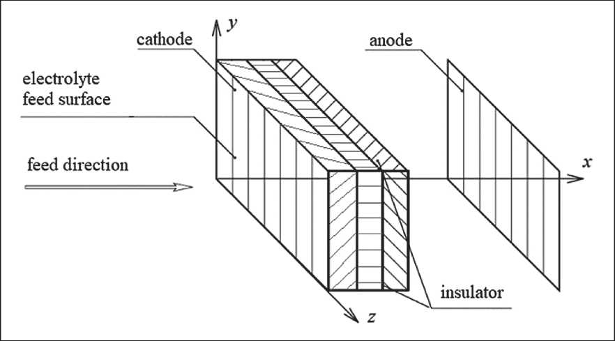
Fig. 1. Schematic of a flow-through three-dimensional electrode with a cathode made of three layers of CFMs
^ = iJ^=^cw = c^ , (16)
where J is total electrode current density.
In order to numerically implement the model (9), (11)–(13), a set of programs was developed and algorithmic programming languages Delphi and Object Pascal were used to write them.
Statement of the optimization problem
Let us consider the problem of calculating the optimal distribution of the specific reaction surface over the thickness of a flow volume porous electrode as a problem of optimal mathematical control of the electrochemical process by selecting the optimal control action u ( x ) = Sv ( x ). Let us denote:
1 /1 1\
;仁南 9 =『 3 ;
zF Jo a = RT:b = lFK^
Е = Уі ; 醬= У2 = /1 ( Уі , У2, Уз, a); d/
攀= ( ? )У2 + a(x) + 丄) Js(x)= ax ks {ks + k" \ks Ki J
= %(Уі , У2 , Уз, 瓦);
Уз(х) = C(%); — =--^/s(x) =/з(Уі , У2 , Уз , а) ・
Equations (14)–(16) will take the form:
dyi / dx = fi ( y 1, y 2, y 3, u ), i = 1, 2, 3 (17)
with boundary conditions:
y 2(0) = (1/κs) J ; y2( L ) = (1/κl) J ; y 3(0) = C 0. (18)
The problem of optimal mathematical control in the general case consists in determining by calculation the control vector-function u ( x ), which ensures the fulfillment of the criterion of the best under given conditions uniformity of distribution of the polarizing current density or potential over the thickness of FTE.
The criterion of uniformity of distribution of the function JS ( x ) can be formulated in different ways. The following form is proposed in this paper:
Thus, the problem is to determine the function u ( x ) such that the solution of equations (17)–(18) satisfies the criterion of the best uniformity of current density distribution over the thickness of FTE.
The following integral criterion is proposed to be used as the uniformity criterion:
Thus, the problem is to determine the function u ( x ) such that the solution of equations (17)–(18) satisfies the criterion of the best uniformity of current density distribution over the thickness of FTE.
The following integral criterion is proposed to be used as the uniformity criterion:
°Q ) = 《《-/§( У1 , Уз)) dx T min. (19)
Method of solving the problem
To solve the problem of optimal mathematical control (17)–(19), it is proposed to use the maximum principle of L. S. Pontryagin [21, 22]. In addition to the obvious advantages, consisting, for example, in an uncomplicated
CONSTRUCTION MATERIALS SCIENCE algorithmization of the maximum principle, it is necessary to note the following circumstance. In the works [13, 20] was presented a study of the stability of the system of differential equations (17), it was shown that the system is unstable, to the variation of initial data and functions in the right-hand side of the system. That is, when carrying out calculations by modeling equations, at significant values of FTE thickness, it may be necessary to apply regularizing methods. It is known that the Pontryagin maximum principle has pronounced regularizing properties [22].
To implement the method of L.S. Pontryagin, the system (17)–(19) should be supplemented with an equation corresponding to the control optimization criterion (19) and, conjugated to equations (17), with a system of differential equations with respect to unknown functions ψ i ( x ) i = 0, ..., 2, related to the main functions by differential relations and initial conditions specified by the method:
dy 0/ dx = (( J / L ) – J S ( y 1, y 3))2 = f 0 ( y 1, y 3, u );
y 0 (0) = 0, (20)
d ψ i / dx = –∑ j =03ψ j (∂ f j /∂ y i ), i = 0, ..., 3;
ψ0 (0) = 1; ψ1 ( L ) = ψ2 ( L ) = ψ3 ( L ) = 0. (21)
The right-hand sides in equations (21), to calculate the derivatives d ψ i / dx , do not require complex transformations and can be presented in an analytical form, which is not difficult for algorithmization and programming when computing on a computer, but the resulting formulas are cumbersome and are not given in this paper for this reason.
In accordance with the method of S.L. Pontryagin, the optimal control u ( x ) is optimal if and only if its values minimize the so-called Hamilton function [21–23]:
H ( x , y 0 ( x ), ..., y 3 ( x ),ψ0 ( x ), ..., ψ3 ( x ), u ( x )) =
∑ i =03ψi (x, y i , u ) f i ( x , ψ i , u ). (22)
It is convenient to minimize the Hamilton function using the well-known method of multivariate gradient descent. Suppose that we have performed k iterations of the search, i.e., we have computed the vector u k ( x ) = ( u 1 k , u 2 k , ..., u m k ).
The numerical values of the functions uk(x) allow us to solve the system (20)–(21), for example, by the classical Runge – Kutta method or any other method [23]. Then we return to the calculation of u k +1( x ) by performing the next step of minimizing the Hamilton function, and so on until the end of the iterative process, ending when the Hamilton function does not change from iteration to iteration within a given accuracy.
Solution of the problem of optimization of the control action distribution u(x) = Sv(x) under some specific conditions.
When solving practical problems of metal extraction on FTE and CFMS metallization, the following assump-
tions and simplifications can often be made. First, it can be assumed that the change in the conductivity of the CFMS over the thickness of the FTE during the electrolysis process is insignificant, i.e., d κs/ dx ≈ 0, and the first summand in equation (14) and subsequent ones can be neglected. Second, we take the uniformity of the electrolysis process distribution over the FTE thickness as a criterion for the uniformity of the electrode potential distribution.
Further, let us assume that the problem of finding the controlling influence u ( x ) = S v ( x ) is solved and the distribution of the metal electrodeposition current density is close to uniform: J S ( x ) = J m . In this case, it can be assumed that the distribution of the electroactive substance concentration over the electrode thickness is close to uniform, and the third equation in the system (17) can be neglected. Then the problem (17)–(22) is simplified to the form:
dy 0/ dx = | E ( x ) – E m |;
dy 1/ dx = y 2;
dy 2/ dx = u ( x )(1/κ s + 1/κl) J m ;
V ψ0 ( x ) = 1; s m
、 d ψ1/ dx = sign( E – E m ); (23)
d ψ2/d x = –ψ1;
y 0 (0) = 0; y 2 (0) = (1/κ s ) J ; y 2 ( L ) = (1/κ l ) J ;
I ψ0 (0) = 1; ψ1 ( L ) = ψ2 ( s L ) = 0.
For this formulation of the problem, the Hamilton function is as follows:
H ( x , y 0, y 1, y 2, ψ0, ψ1, ψ2, u ) = –| E ( x ) – E m | +
+ ψ1 y2 + ψ2 u(x)(1/κs + 1/κl)jm.(24)
From the system of equations (23) it is not difficult to determine:
ψ1 (x) = (x – L) sign(E – Em),(25)
ψ2 (x) = 1/2 (x – L)2 sign(E – Em)(26)
and, therefore,
H = –| E ( x ) – E m | + ( x – L ) sign( E – E m ) y 2 +
+ 1/2 (x – L)2 sign(E – Em) u(1/κs + 1/κl) Jm.(27)
Analyzing relation (27), it is easy to see that the control action u = S v enters the expression for the Hamilton function linearly, and the calculation of the partial derivative H on this variable, followed by equating this derivative to zero, does not lead to the solution of the problem. However, we note that the function H = H ( u ) will have a minimum when the third summand in expression (27) is minimal. Considering the known U-shaped form of the potential distribution function E ( x ) along the electrode
CONSTRUCTION MATERIALS SCIENCE thickness [24], we can conclude that in the case when E > Em, the value u(x) = S v(x) should be minimal, and when E < Em – maximum possible. It follows that the situation when the initial layers of the CFMS have a smaller specific reaction surface, then, in the middle part of the electrode – a larger one and then again a smaller one is preferable from the point of view of uniformity of the FTE potential distribution along the thickness.
An example of solving the problem of effective selection of CFMs layers of a volume-porous cathode in order to improve the uniformity of the deposited metal distribution over the thickness of FTE.
Let us consider the results of calculated and experimental distribution of copper precipitation in 6 mm thick PTE when using AMN (Fig. 2) and VNG-50 (Fig. 3) as cathode material, the values of specific reaction surface of which differ significantly: 180 cm–1 and 265 cm–1, respectively. 3. It should be noted that, as before, all the results of experimental studies were obtained by Prof. V.K. Va-rentsov and published, for example, in [14, 20]. Electro- lyte composition (g/l): CuSO4·5H2O – 170, H2SO4 – 25, (NH4)2SO4 – 80; specific conductivity 0.101 cm/cm; copper ion concentration 0.16±0.03 g/l. Copper deposition was carried out at an overall current density of 500 A/m2. In Fig. 2 and Fig. 3 red piecewise linear functions correspond to the experiment, blue – to the calculation at electrolysis duration, min: a, b – 60, c, d – 180, – and with electrolyte flow rate, cm/s: a, c – 0.4, b, d – 1.0.
The computational results and experimental data shown in Fig. 2 and Fig. 3, are in good agreement with each other. It can also be noted that during the metallization of the carbon graphite cathode made of VNG-50 grade CFMS, the total amount of deposited metal exceeds the total amount of metal deposited on the cathode made of AMN grade CFMs, which is explained by the better specific conductivity of VNG-50 grade material. It is easy to see that the distribution of copper over the thickness of the cathode made of AMN grade CFMS is more uniform than the distribution of copper over the thickness of the cathode made of VNG-50 grade CFMS.
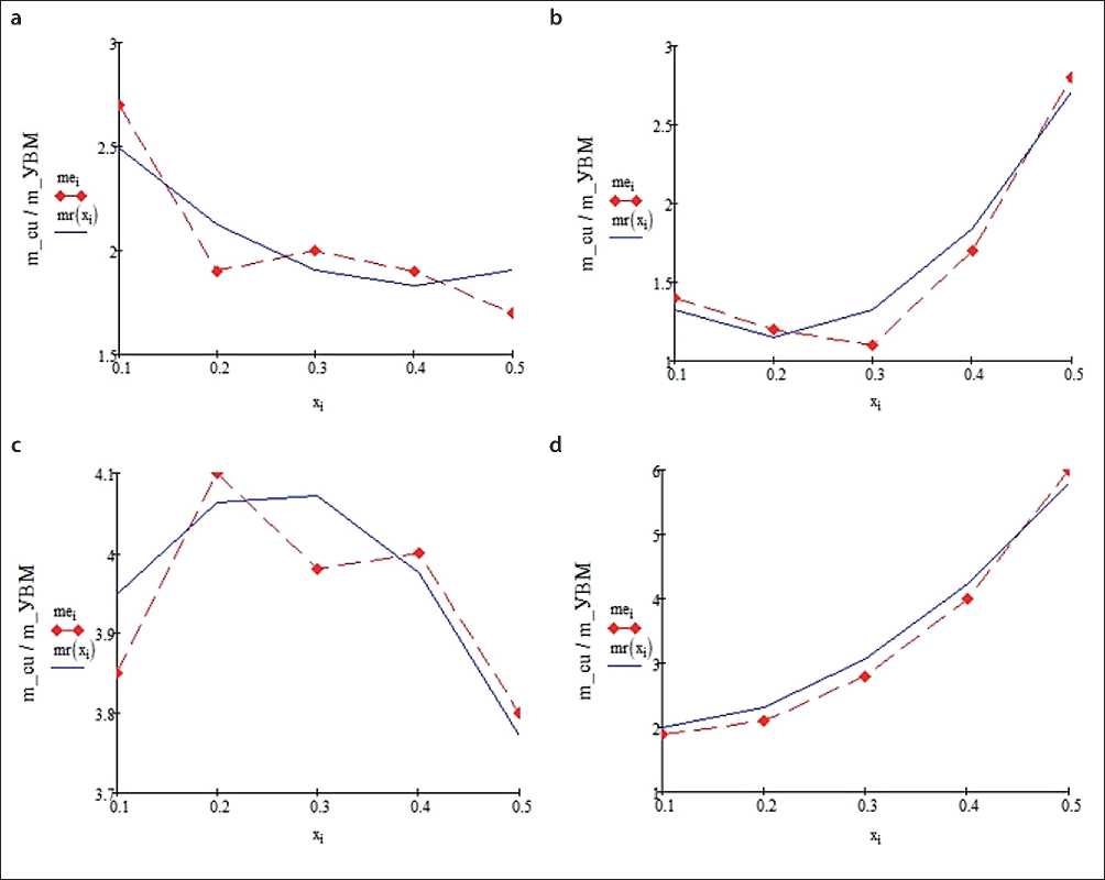
Fig. 2. Metal distribution along the thickness of the ANM cathode
CONSTRUCTION MATERIALS SCIENCE
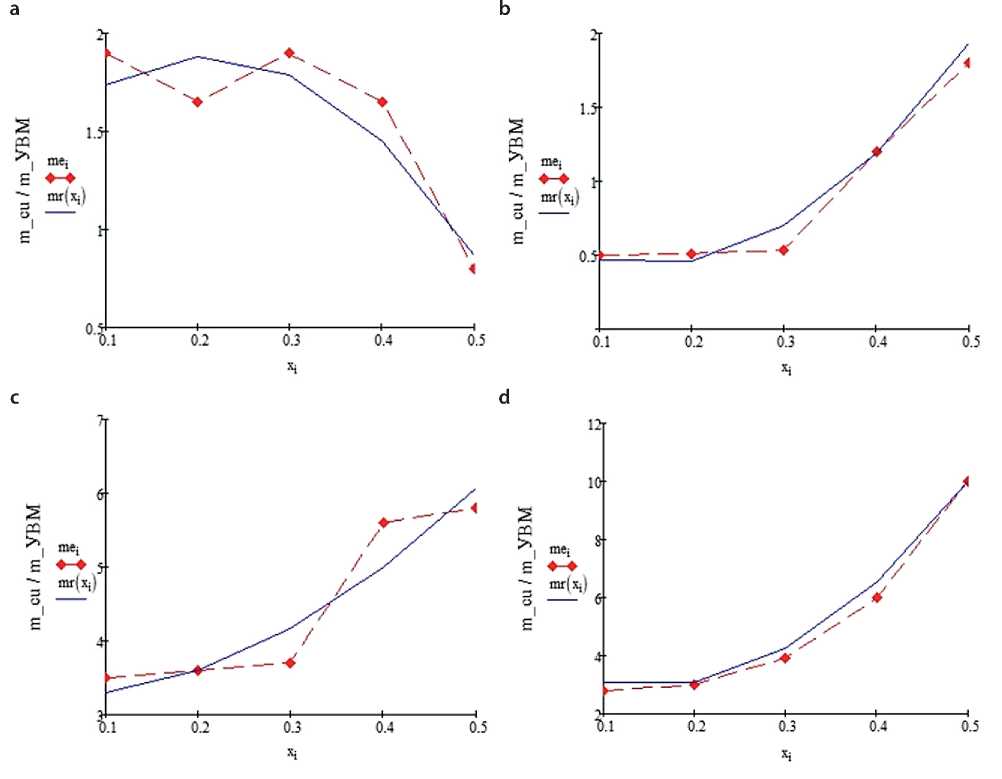
Fig. 3. Metal distribution along the thickness of the VNG-50 cathode
In accordance with the theoretical conclusions given above, it can be assumed that in order to improve the uniformity of the distribution of copper coating of FTE, it is possible to use a volume-porous cathode made of three layers of CFMS in the following sequence: the first layer – from AMN grade CFMs, the second layer – from VNG-50 grade CFMs and the third layer – again from AMN grade CFMs.
Fig. 4 shows the calculated data of copper sludge distribution in FTE consisting of three CFMs layers: AMN; VNG-50; AMN.
Numerical processing of the calculation results shown in Figs. 2–4 allowed us to compile Table 2, the data of which reflect the indices of uniformity of copper distribution over the thickness of the FTE for the considered conditions given above. Here max/min is the index of uniformity of precipitate distribution: max – the largest thickness of precipitate, min – the minimum thickness of precipitate, under different conditions and design features of the volume-porous cathode.
The main conclusion that follows from the analysis of the results of calculations of the best copper distribution through the thickness of the flow-through volumetric porous cathode is that in all series of calculations the best index of uniformity of copper precipitate distribution in FTE is observed in the case of using the cathode composed of three layers of CFMS grades AMN, VNG-50, AMN, successively.
RESULTS AND DISCUSSION
The paper proposes an approach to solving the problem of improving the uniformity of metallic coating in the volume of carbon fiber material, which is the basis of composite and nanocomposite material, during galvanic metallization of CFMS due to the correct formation of FTE from layers of CFMs of different grades with different values of specific reaction surface.
The problem is solved by the method of mathematical modeling and subsequent calculation using the classical
CONSTRUCTION MATERIALS SCIENCE
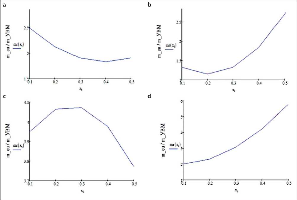
Fig. 4. Distribution of copper precipitate in FTE from three CFMS layers: 1 – AMN, 2 – VNG-50, 3 – AMN, under the following conditions: a – electrolyte flow rate, v = 0.4 cm/s, electrolysis time, t = 60 s; b – v = 1 cm/s, t = 60 s; c – v = 0.4 cm/s, t = 180 s; d – v = 1 cm/s, t = 180 s
Table 2. Values of the uniformity index (max/min) of copper deposit distribution over the thickness of FTE
|
1st CFMS layer |
2ndCFMS layer |
1st CFMS layer |
Flow rate, v , cm/s |
Electrolysis time, t , s |
max/min |
|
AMN |
AMN |
AMN |
0.4 |
60 |
1.40 |
|
VNG-50 |
VNG-50 |
VNG-50 |
0.4 |
60 |
2.05 |
|
AMN |
VNG-50 |
AMN |
0.4 |
60 |
1.30 |
|
AMN |
AMN |
AMN |
1.0 |
60 |
2.30 |
|
VNG-50 |
VNG-50 |
VNG-50 |
1.0 |
60 |
4.44 |
|
AMN |
VNG-50 |
AMN |
1.0 |
60 |
2.16 |
|
AMN |
AMN |
AMN |
0.4 |
180 |
1.20 |
|
VNG-50 |
VNG-50 |
VNG-50 |
0.4 |
180 |
1.88 |
|
AMN |
VNG-50 |
AMN |
0.4 |
180 |
1.07 |
|
AMN |
АМН |
AMN |
1.0 |
180 |
2.75 |
|
VNG-50 |
VNG-50 |
VNG-50 |
1.0 |
180 |
3.34 |
|
AMN |
VNG-50 |
AMN |
1.0 |
180 |
2.60 |
CONSTRUCTION MATERIALS SCIENCE maximum principle of L.S. Pontryagin, which allows us to formulate and solve the problem of optimization of the distribution of potential, current density and metal deposit over the thickness of FTE. In this case, the distributed specific conductivity of the electrode is taken as a controlling influence.
When developing mathematical models describing galvanic processes in FTE, the possible change of characteristic electrochemical and technological parameters, including the specific reaction surface of CFMs in the process of electrolysis due to changes in the structure of CFMs during metallization of carbon-graphite filaments was taken into account.
Using the elements of regression analysis, regression equations linking the values of specific reaction surface of CFMS depending on the value of the carbon graphite fiber radius and porosity of the carbon graphite material have been constructed and studied.
The use of natural simplifications and transformations made it possible to bring mathematical descriptions to the form of systems of ordinary differential equations, which, in turn, made it possible to present and solve the optimization problem in analytical form and formulate some practical recommendations on the use of CFMs cathodes with a distributed reaction surface.
As examples, practical problems of calculation of copper precipitate distribution during metallization of CFMs
of different grades are solved, it is shown that the use of CFMs cathode of three layers provides more uniform distribution of metal over the thickness of the electrode.
CONCLUSION
The development of mathematical models based on modern provisions of the electrochemical theory of metal electrodeposition on flowing carbon graphite cathodes and methods of mathematical modeling allows describing electrolysis processes in FTE in the form of boundary value problems of mathematical physics, for the solution of which it is necessary to use high-level mathematical apparatus. At the same time, the developed mathematical models allow us to formulate the problems of optimization of metallization processes of carbon fiber materials due to the optimal distribution of specific reaction surface over the thickness of the flowing three-dimensional electrode.
Mathematical modeling and numerical calculation methods in the considered case represent an effective scientific method for research and finding parameters of optimal control of electrochemical processes in porous medium. The presented methods and algorithms can be used as a tool for theoretical studies of regularities of metal electrodeposition in FTE and for numerical calculations of optimal technological parameters of the electrolysis process and electrolyzer design elements.
