Doppler Shift Impact On The MIMO OFDM System In Vehicular Channel Condition

Author: Samarendra Nath Sur,Rabindranath Bera
Journal: International Journal of Information Technology and Computer Science(IJITCS) @ijitcs
Article in issue: 8 Vol. 4, 2012.
Free access
Vehicle-to-vehicle (V2V) communication systems will play an important role in intelligent transportation systems (ITS). But in high mobility road condition, orthogonal frequency division multiplexing (OFDM) is very sensitive to Doppler shift. In this scenario multiple input and multiple output (MIMO) system combined with OFDM, make MIMO -OFDM techniques very attractive and productive for vehicle-to-vehicle communications. This paper deals with the bit error rate (BER) performance analysis of MIMO-OFDM system in high way road condition which is modeled based on the Nakagami fading characteristic. The system performance is analyzed with the change in m value of Nakagami channel and also with the variation in the modulation schemes.
MIMO, OFDM, Nakagami Channel, Doppler Shift, Inter carrier interference, Bit error rate
Short address: https://sciup.org/15011725
IDR: 15011725
Text of the scientific article Doppler Shift Impact On The MIMO OFDM System In Vehicular Channel Condition
Published Online July 2012 in MECS
Intelligent transportation system (ITS) increases safety, security and efficiency of transport systems [1]. Many countries throughout the world have already implemented some ITS applications such as traffic management, traveler information, vehicle system, public transport, emergency management, electronic payment and security-safety. Vehicle-to-Vehicle (V2V) communication is an integral part of Intelligent Transportation Systems (ITS) [2, 3]. This will allow nearby vehicles to communicate with the other vehicles without the dependence on any infrastructure or roadside equipment and this will enable the on road vehicle to exchange the necessary information to minimize the collision.
Rapid growth in communications technologies and increasing user demands lead to the requirement of using a reliable wireless links with large band width capacity. A technique which promises high data rates is the Vertical Bell Labs Layered Space-Time (V-BLAST) architecture. On the other hand orthogonal frequency division multiplexing (OFDM) is robust against frequency selective fading and provides relatively simple receiver implementation [4, 5]. And also OFDM is considered as a very promising technique for achieving very high bit rate transmission. Because of its inherent advantages, it has been already accepted in many transmission applications including mobile radio channels, high-bit-rate digital subscriber lines (HDSL), asymmetric digital subscriber lines (ADSL), wireless local area network (Wireless LAN), digital audio broadcasting (DAB), 3GPP long term evolution (LTE) and digital video broadcasting (DVB) [6, 7]. Hence the use of V-BLAST MIMO with OFDM leads to promising next generation wireless communication applications [8, 9].
In a MIMO-OFDM system, inter-symbol interference (ISI) caused by multi-path propagation (time dispersion) [9] can be eliminated by adding a frequency guard interval dubbed the cyclic prefix (CP) between adjacent OFDM symbols. However, the CP offer no flexibility against frequency dispersion, where carrier frequency offset is introduced due to the Doppler spread. This cause a loss of orthogonality between the subcarriers, and results in inter carrier interference (ICI) [10]. This loss in orthogonality makes the OFDM sensitive to inter-carrier interference (ICI) due to carrier frequency offset (CFO) and Doppler shift [11, 12, 13]. Therefore, the above said advantage comes at the expense of the sensitivity to frequency offset leading to inter-channel interference and hence performance degradation.
The Nakagami-m channel model is a multipurpose model and it can be considered as channel model in the highway scenario. Through extensive study it has been identified as a suitable probabilistic channel model for the vehicular network. However, the transmitter and receiver are moving at high speeds in V2V environments. This causes different fading statistics depending on the existence of a line-of-sight (LOS). It has already been proved that the m parameter changes in inverse proportion with distance.
Let γ represent the instantaneous signal to noise ratio (SNR) and it can be defined as
Y = P
2 Es
N0
Where P is the fading amplitude, Es is the energy per symbol, and N0 is the noise spectral density. The probability distribution function of в for the Nakagami-m fading channel is given by
m
М» = 2_ I m 1 e 2m - 1exp P F (m) (nJ
( э A
. - m P 2
Q
V
,
P> 0, m > 1 (2)
analyzed for different modulation scheme such as (Mary phase shift keying) MPSK and (M-ary quadrature amplitude modulation) MQAM with Nakagami channel.
The remainder of this paper is organized as follows: First, a short description on the V-BLAST MIMO system model in section II. Followed by mathematical analysis on ICI and BER calculation in sections III and IV respectively. In Section V, the simulation results and comparisons are given. Conclusions are drawn in the last section.
V
Where Г (.) represents the Gamma function, n = EP 2
and m is the parameter of fading depth that ranges from 0.5 to infinity and this parameter is responsible for the variation in fading condition.
The fading parameter m is defined by the equation as given below e2[P2]
var[ P 2 ]
Then the probability density function (PDF) of the instantaneous SNR γ is given by [14, 15]
m
1 I m I I - m y I
P y ( у ) = I I Y exp l I , Y> 0 (4)
r (m) ( у J ( Y J
0 0.5 1 15 2 25 3
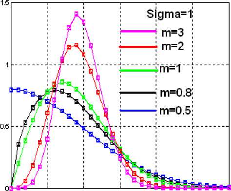
Fig 1: PDF of Nakagami Channel.
Rayleigh fading conditions, i.e. no line-of-sight exists, can be obtained through Nakagami by setting m = 1. Higher values of m can be used for approximating Rician distributed channel conditions where a line-of-sight path exists, while for m <1, the channel conditions are worse than the Rayleigh distribution.
In this paper, the performance of a V-BLAST MIMO OFDM system in the presence of CFO is considered. In presence of Doppler, the system performance has been
-
II. V-BLAST-MIMO OFDM System Model
In V-BLAST the signal is spatially equalized on a layer basis. OFDM data symbols sent through each individual transmit antenna is referred to as a layer in the V-BLAST.
We consider a V-BLAST OFDM system with T transmit and R receive antennas. And also we consider that perfect channel state information (CSI) is available at the receiver. Figure below shows a basic block diagram of a VBLAST MIMO OFDM system.
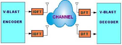
Fig 2: VBLAST MIMO-OFDM system model
At the transmitter incoming bits are mapped on a modulation constellation using MPSK or MQAM, the layered using VBLAST algorithm. This layered data then feed to the OFDM modulation block. The OFDM signal for each antenna is obtained by applying the Inverse Fast Fourier Transform (IFFT) on the transmitter side. A cyclic prefix (CP) is inserted in front of the OFDM symbol at the final step of OFDM modulation block. Cyclic prefix is used to reduce the inter symbol interference (ISI). At the receiver side Fast Fourier transform (FFT) is applied after removing the CPs. Then Channel estimation using VBLAST zero forcing (ZF) detection is done for each OFDM subcarrier followed by demodulation.
-
III. ICI Analysis
An OFDM system basically consists of a parallel transmission, signal modulation and IFFT/FFT [11-14]. Each parallel data is mapped with MPSK/ MQAM digital modulation scheme and, then, those data are modulated by an IFFT on N-parallel subcarriers. After adding cyclic prefix, the parallel data streams are converted to serial one and then the complete OFDM symbol is transmitted over a discrete-time channel. At the receiver, again the serial data stream is converted to parallel one. After the removal of cyclic prefix, the data are retrieved by a FFT and, then, demapped with corresponding scheme to obtain the estimated data.
In a OFDM system the transmitted signal can be represented by
x(n) = ^Nfx(p)e j2 n pn/N (5)
N p = 0
where x(n) denotes the nth sample of the OFDM transmitted signal, X(p) denotes the modulated symbol over the pth subcarrier and N is the total number of the subcarriers.
The received signal in time domain after DFT could be written as
Y(p) = N S y(n)e - j2 n pn / N + G(p) (6)
N n = 0
Where G (p) denotes an additive white Gaussian noise for the pth subcarier.
Assuming the channel frequency offset normalized by the subcarrier frequency spacing denotes as ε and discrete time domain OFDM signal y (n) is multiplied by the factor e j2 n n s /N in (6) to resent the frequency offset.
As in [11], (6) can be written as
N - 1
Y(p) = S(0)H(p)X(p) + S S(l - p)H(l)X(l) + N(p) (7)
l = 0,l * p
Where p=0, 1 -----, N-1.
The ICI coefficient between lih and pih sub-carrier, S (l-p) can be expressed as
. sin(n(l-p + c)) „ 1.,. ......
S(l - p) =------"----------exp[jn(1- —)(l - p + e)]
Nsm(~(l - p + s ))
and sinc(e)1
S(0) =-----— exp[jn(1 - —)e](9)
■ < e AN sin c( )
N
Here, S(0) produces the phase rotation to the modulated symbol for pth subcarrier.
The first term in (7) represents the carrier component and the average power on the pth subcarrier can be written as
E[C(p)| 2 ] = E[|X(p)H(p)S(0)| 2 ] (10)
The second term represents the ICI component and the average power of it can be written as
E[|I(p)|2] = E[
N - 1
S S(l - p)H(l)X(l) l = 0,l * p
]
Therefore, the average SINR for the pth subcarrier can be represented as
SINR(p) =
E[
E[X(p)H(p)S(0) 2]
N - 1
S S(l - p)H(l)X(l) ] l = 0,l * p
When SNR is high, the achievable system bit error rate (BER) performance in presence of the frequency offset is governed by (signal to interference noise ratio) SINR.
IV. BER Calculation
The moment generating function (MGF) [16, 17] of the SNR in Nakagami-m fading is given by
TO
Фу (s) = J exp( - s y )P y ( y )d y = 0
m m + sy

m > —
The conditional- error probability (CEP) for M-PSK is given by
Ps( Y ) = 1
п/ п /M -Y™2(пm)
J exp ----y—M
0 sin 2 9
к У
d 9
The average symbol error rate in Nakagami channel for positive value of fading depth m is given by
TO
Ps = J Ps ( Y ) P y ( Y ) d Y (15)
= 1Is п
у - \
0, к
п
—
п/
M,
Y
к m у
sin2 (п^),
m
У
As in [16], the generalized form of Is can be
expressed as
9 U
Is( 9 L, 9Uc, d) = J 9 l
= 9 u -9 l

sin2 9
c + sin2 9
d d9
I ё Г 1 d-1 1
-.--- - + X (c, 9u) s ------- T
^ c + 1 [ 2 ' U 'J k = 0 [ 4(c + 1) ] k
+ ^kSE 1
п h = 0

sin [ 2(k - h) X (c, 9 u)] +
k - h
c
С + 1
К ""I d-1
- + X(c, 0 l) E
-2 J k=0 [4(c + 1)]k х 5
- h) X (c, 0 l)] , k - h ’
Where d (=m) is a positive integer and
X (q, 0 ) = tan 1

cot ( n - 0 )
c= [ m) sin2 (nM)
L=Total no of diversity branches h= (0,1,2,......L)
kkth signal point with instantaneous SNR y
As in [16], from the power series expansion of (2) it can be derived that at the higher SNR region the PDF of the fading amplitude ( P ) is inversely varying with the signal SNR level. And the proportionality relation changes with the variation in Nakagami fading shape parameter. For m= 0.5 (one-sided Gaussian), the PDF changes inversely with SNR level whereas for m=1 (Rayleigh fading) and m=2 (Rician fading) it is proportional to inverse of the square and fifth power of the SNR level respectively. Therefore, error probability rate in Nakagami fading channel with m=0.5 is worse than that of Rayleigh and Rician channel.
The BER of coherent M-QAM with two-dimensional Gray coding over the Additive White Gaussian Noise (AWGN) channel.
P^' 5 02cxp(5i M - T))
The average BER in a slow and flat Nakagami-m fading channel may be derived by averaging the error rates for the AWGN channel over the PDF of the SNR in Nakagami-m fading:
______ да
Pb( Y ) = J Pb( Y )xP Y ( Y )d Y
-да
да
J 0.2exp(
1 x r (m)

m-1 f-my\
Y expl -^- d Y
I Y J
2(M - 1)
Now after some simplification as in [18], the average BER can be calculated as given below:
Pb( Y ) = 0.2
2m (M - 1)
3 y + 2m(M - 1) ?
Table 1 BER values in Two SNR regions.
|
At SNR 12 dB |
BER |
At SNR 3 dB |
BER |
|
m=0.9 |
0.05968 |
m=0.9 |
0.4678 |
|
m=1 |
0.02924 |
m=1 |
0.3738 |
|
m=2 |
0.0007984 |
m=2 |
0.2798 |
V. Simulation Results
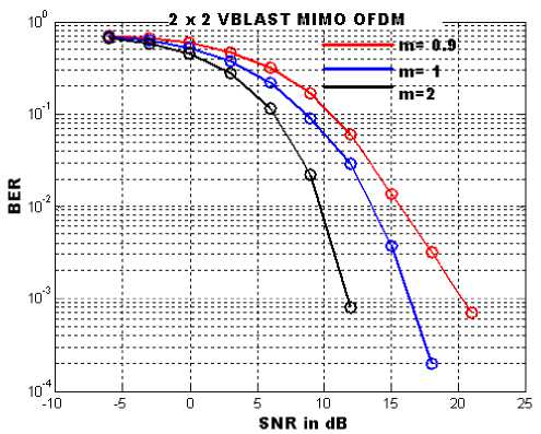
Fig 3: SNR vs. BER Curves for 2x2 VBLAST MIMO-OFDM in Nakagami channel
Above figure shows the BER performance of the 2x2 VBLAST MIMO OFDM system in Nakagami channel condition. As in figure with the change in m values the performance of the system gets better. This improvement in the BER performance is due to the basic fading characteristics of the Nakagami channel, as with the increment of the m value, Nakagami fading characteristics changes from one sided Gaussian distribution to Raleigh distribution. Table 1 represents the system performance with different m values in two SNR regions (high SNR region at 12 dB and low SNR region at 3 dB). As in table with the change in m values at the high SNR level the system performance improves dramatically with respect to that of in low SNR level.
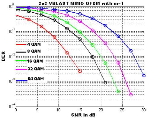
Fig 4: SNR vs. BER Curves for 2x2 VBLAST MIMO-OFDM in Nakagami channel with different modulation schemes
Table 2 BER values in Two SNR regions
|
At SNR 15 dB |
BER |
At SNR 3 dB |
BER |
|
4 QAM |
0.002595 |
4 QAM |
0.3027 |
|
8 QAM |
0.0493 |
8 QAM |
0.6429 |
|
16 QAM |
0.09481 |
16 QAM |
0.7456 |
|
32 QAM |
0.2588 |
32 QAM |
0.8564 |
|
64 QAM |
0.5019 |
64 QAM |
0.9004 |
Figure 4 depicts the BER performance of 2x2 VBLAST MIMO OFDM system in Nakagami channel condition (m=1) with the variation in the modulation order of MQAM modulator. As in table 2 with the increment in the modulation order the BER performance of the system is degraded. Table 2 represents the system performance in two SNR regions (high SNR region at 15 dB and low SNR region at 3 dB). From the table 2, one important conclusion can be drawn, that is the effect of modulation order on the system performance changes differently in these two regions.
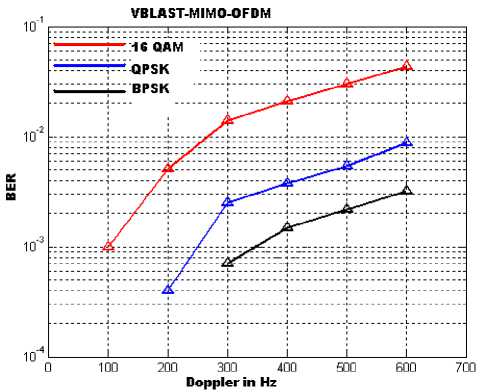
Fig 5: Performance of 2x2 VBLAST MIMO-OFDM systems with different Doppler frequency
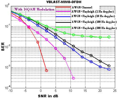
Fig 6: SNR vs. BER Curves for 2x2 VBLAST MIMO-OFDM with different Doppler frequency.
Above figure shows the impact of the Doppler shift on the BER performance of a 2x2 VBLAST MIMO OFDM system with 16QAM modulation. With the increment of Doppler shift the BER value increases.
-
VI. Conclusion
This paper deals with the details analysis on the performance of the VBLAST MIMO-OFDM in mobility condition i.e. the effect of the Doppler shift on the system. For a 2x2 system simulation results showed that with increasing CFO, the BER increases. And also the system performance is analyzed with the variation in modulation order. From the simulation, it can be concluded that MIMO- OFDM is emerging as a promising solution for the V2V communication in severe multi-path condition and also in high mobility condition.
As discussed earlier Doppler effect introduce carrier frequency offset in OFDM system and this results in performance degradation. Degradation in the system performance is noticed as shown in figure 5. Larger the Doppler shift more is the degradation in BER performance. And also one important conclusion can be drawn out of the simulation result is that with the higher order modulation the system become more sensitive towards Doppler change.
References Doppler Shift Impact On The MIMO OFDM System In Vehicular Channel Condition
- Huang, X; (2006):”Smart Antennas for Intelligent Transportation Systems”, 6th International Conference on ITS Telecommunications Proceedings, 2006.
- J.Njordand et.al. “Safety Applications of Intelligent Transportation Systems in Europe and Japan, American Trade Initiatives, January 2006.
- Nirmalendu Bikas Sinha1, Manish Sonal, Makar Chand Snai, R.Bera and M.Mitra, “Modelling and Implementation of ITWS: An ultimate solution to ITS”, Journal Of Telecommunications, Volume 2, Issue 1, February 2010, Pp-17-27.
- Masaaki Harada, “Performance analysis of coded MIMO OFDM in multipath fading channel”,IEICE Electronics Express, vol.8, No.19, pp-1596-1601.
- Ghasan Ali Hussain, Makhfudzah Bt. Mokhtar and Raja Shamsul Azmir B. Raja, “Concatenated RS-Convolutional Codes for MIMO-OFDM System”, Asian journal of applied science 4(7), 2011, pp-720-727.
- M.P. CHITRA and Dr. S.K.SRIVATSA, “Ber Analysis Of Coded And Uncoded Mimo-Ofdm System In Wireless Communication”, IJCSE, Vol. 1 No. pp-4 357-363.
- A. Omri and R. Bouallegue, “New Transmission Scheme For Mimo-Ofdm System”, IJNGN, Vol.3, No.1, March 2011, pp- 11-19.
- F.Javier L´opez-Marti´ınez, Eduardo Martos-Naya, Jose´ F. Paris, AndreaJ.Goldsmith, “BER Analysis for MIMO-OFDM Beamforming with MRC under Channel Prediction and Interpolation Errors”, IEEE "GLOBECOM" 2009.
- Zhongshan Zhang, Lu Zhang, Mingli You, and Ming Lei, “Bit Error Rate Approximation of MIMO-OFDM Systems with Carrier Frequency Offsetand Channel Estimation Errors”, EURASIP Journal on Wireless Communications and Networking, Volume 2010,ArticleID176083, pp 1-14.
- Tiejun (Ronald) Wang, ,John G. Proakis, Elias Masry, and JamesR. Zeidler, “Performance Degradation of OFDM Systems Due to Doppler Spreading”, IEEE Transactions On Wireless Communications, VOL.5, NO.6, JUNE 2006, pp-1422-1432.
- Himal A. Suraweera and Jean Armstrong, “Performance of V-BLAST MIMO-OFDM Systems with Carrier Frequency Offset” Au sCTW 2005, 2005, pp-73-78.
- J. Armstrong, P. M. Grant and G. Povey, “Polynomial cancellation coding of OFDM to reduce the intercarrier interference due to Doppler spread,” in Proc. IEEE GLOBECO M 98 , Sydney, Australia, Nov. 1998 , pp. 2771-2776.
- Srabani Mohapatra and Susmita Das, “Performance Enhancement of OFDM System with ICI Reduction Technique”, Proceedings of the World Congress on Engineering 2009, Vol 1, WCE 2009, July 1-3, 2009.
- Hyundong Shin, and JaeHong Lee, “On the Error Probability of Binary and M-ary Signals in Nakagami-m Fading Channels” IEEE Transactions On Communications, VOL.52, NO.4, APRIL 2004.
- Li Tang Zhu Hongbo, “Analysis and Simulation of Nakagami Fading Channel with MATLAB”, CEEm 2003, Nov. 4-7, Hangzhou, China, pp- 490-494.
- A. Annamalai, and C. Tellambura, “Error Rates for Nakagami-m Fading Multi-channel Reception of Binary and M-ary Signals”, IEEE Transactions On Communications, VOL. 49, NO.1, JANUARY 2001.
- M.K. Simon and M.-S. Alouini, “Digital Communication Over Fading Channels: A Unified Approach to Performance Analysis”. NewYork: Wiley,2000.
- Tahmid Quazi and HongJun Xu1, “Performance analysis of adaptve M-QAM over a fat-fading Nakagami-m channel”, S Afr J Sci. 2011;107(1/2), Art. #122, 7 pages. DOI: 10.4102/sajs.v107i1/2.122.
