Downlink and Uplink Physical Channels in Long Term Evolution

Author: A. Z. Yonis, M. F. L. Abdullah
Journal: International Journal of Information Technology and Computer Science(IJITCS) @ijitcs
Article in issue: 11 Vol. 4, 2012.
Free access
Long Term Evolution (LTE) defines a number of physical channels to carry information blocks received from the MAC and higher layers. This paper presents two types of Physical channels: the first type is downlink physical channels which consist of Physical Broadcast Channel (PBCH), Physical Downlink Shared Channel (PDSCH), Physical Multicast Channel (PMCH), Physical Downlink Control Channel (PDCCH), Physical Control Format Indicator Channel (PCFICH) and Physical Hybrid ARQ Indicator Channel (PHICH). The second type of Physical channels is uplink physical channels which consist of Physical Uplink Shared Channel (PUSCH), Physical Uplink Control Channel (PUCCH) and Physical Random Access Channel (PRACH). This paper also highlights the structure of PDSCH and PUSCH, discuss the algorithms of the two types of physical channel and each of its features. The aim of this paper is to discuss the well-designed PHY Channels which provide high cell-edge performance with specific features, such as dynamic bandwidth allocation to users, the design of reference signals and control channels. These channels take into account a more challenging path loss and interference environment at the cell edge.
LTE, Downlink Physical Channel, Uplink Physical Channel
Short address: https://sciup.org/15011776
IDR: 15011776
Text of the scientific article Downlink and Uplink Physical Channels in Long Term Evolution
Published Online October 2012 in MECS
In this paper the physical layer of LTE is described, based on the use of Orthogonal Frequency Division Multiple Access (OFDMA) and Single Carrier Frequency Division Multiple Access (SC-FDMA) principles as covered in this paper. The LTE physical layer is characterized by the design principle of resource usage based solely on dynamically allocated shared resources rather than having dedicated resources reserved for a single user.
The physical layer of a radio access system has a key role in defining the resulting capacity and becomes a
-
II. LTE Channel Types
There are three categories into which the various data channels may be grouped.
-
■ Physical channels: These are transmission channels that carry user data and control messages.
-
■ Transport channels: The physical layer
transport channels offer information transfer to Medium Access Control (MAC) and higher layers.
-
■ Logical channels: Provide services for the Medium Access Control (MAC) layer within the LTE protocol structure.
This paper presents the physical channels for both types of downlink physical channels and uplink physical channels plus highlight on the PDSCH and PUSCH.
-
III. Downlink Physical Channels
-
3.1 Transport Channels
-
3.1.1 Physical Broadcast Channel (PBCH)
-
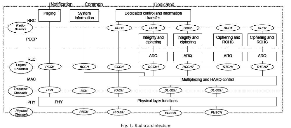
LTE defines a number of downlink physical channels to carry information blocks received from the MAC and higher layers. These channels are categorized as transport or control channels as Fig. 1 shows radio architecture.
The PBCH carries the MIB (Master Information Block) and has a payload of only 24 bits. The MIB informs DL bandwidth, the frame number and the PHICH configuration. Additionally, DL antenna configuration, 40 ms timing and the TX diversity type used for PBCH are also informed. Fig. 2 shows antenna port reference signal allocation.
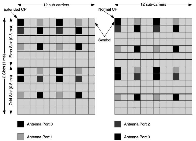
Fig. 2: Antenna port reference signal allocation
This channel information is essential for decoding the remaining of the frame; therefore it is transmitted in a highly reliable form. A 16 bit cyclic redundancy check (CRC) is added to the payload and a 1/3 convolutional code is then applied, resulting in a total of 120 bits. The modulation technique used is quaternary phase shift keying (QPSK), resulting in 60 symbols.
The channel has assigned the first four symbols of slot 1 on 72 sub-carriers centered on the carrier frequency (4 sets of 6 resource blocks (RBs)). This implies that the information is always available at the same location regardless of the bandwidth. The channel information fits into one set of RBs, so that it has a repetition of 4 times per frame. The PBCH TTI (Transmission Time Interval) is 40 ms, therefore the channel is repeated again in the three following frames, to a total of 16 repetitions (12 dB gain)[3].
-
3.1.2 Physical Downlink Shared Channel (PDSCH)
The PDSCH is the main data bearing channel which is allocated to the users on a dynamic and opportunistic basis. The PDSCH carries data in what's known as Transport Blocks (TB) which correspond to a MAC PDU. They are passed from the MAC layer to the PHY layer once per TTI which is 1 ms (i.e. 1 ms scheduling interval to meet low latency requirements).
In order to guard against propagation channel errors, convolutional turbo coder is used for forward error correction. The data is mapped to spatial layers according to the type of multi-antenna technique (e.g. closed loop spatial multiplexing, open-loop, spatial multiplexing, transmit diversity, etc.) and then mapped to a modulation symbol which includes QPSK, 16 Quadrature amplitude modulation (QAM) and 64 QAM. Physical resources are assigned on a basis of two resource blocks for one TTI (1 ms). This is referred to as 'pair of resource blocks' which is the quantum of resources that can be allocated. It corresponds to 12 sub-carriers (180 kHz) for 14 OFDM symbols (normal cyclic prefix (CP) mode).
The PDCH is also used to transmit broadcast information but not to transmit on the PBCH which include System Information Blocks (SIB) and paging messages.
The different steps of the DL-SCH physical layer processing are outlined in Fig. 3. In the case of carrier aggregation – that is, transmission on multiple component carriers in parallel to the same terminal of the transmissions on the different carriers correspond to separate transport channels with separate and more or less independent physical-layer processing. The transport-channel processing is outlined in Fig. 3 and the discussion below is thus valid also in the case of carrier aggregation.
CRC insertion per transport block
Code-block segmentation including possible per-code-block CRC insertion
Channel coding (Turbo coding)
Rate matching and physical-layer hybrid ARQ functionality
Bit-level scrambling
Data modulation
(QPSK, 16QAM, 64QAM)
Antenna mapping
One or two transport block(s) of dynamic size delivered from the MAC layer
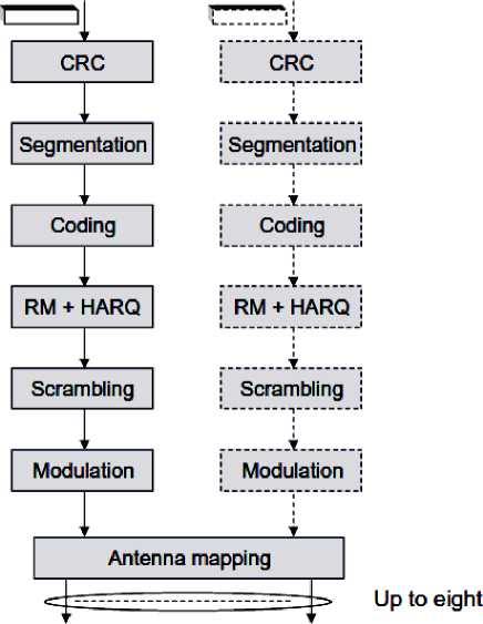
antenna ports
Mapping to OFDM time-frequency grid for each antenna port
Fig. 3: Physical layer processing for DL-SCH [4]
Within each Transmission Time Interval (TTI), corresponding to one subframe of length 1 ms, up to two transport blocks of dynamic size are delivered to the physical layer and transmitted over the radio interface for each component carrier. The number of transport blocks transmitted within a TTI depends on the configuration of the multi-antenna transmission scheme [4]
-
❖ In the case of no spatial multiplexing there is at most a single transport block in a TTI.
-
❖ In the case of spatial multiplexing, with transmission on multiple layers in parallel to the same terminal, there are two transport blocks within a TTI.
-
3.1.3 Physical Multicast Channel (PMCH)
-
3.2 Control Channels
-
3.2.1 Physical Downlink Control Channel (PDCCH)
-
3.2.2 Physical Control Format Indicator Channel (PCFICH)
-
3.2.3 Physical Hybrid ARQ Indicator Channel
This channel defines the physical layer structure to carry Multimedia Broadcast and Multicast Services (MBMS). However, MBMS are not included in the first release of LTE. The PMCH is designed for a singlefrequency network and it requires that the base stations transmit with tight time synchronization at the same modulated symbols. The PMCH is transmitted in specific dedicated to subframes where the PDSCH is not transmitted.
Control occupy the first 1, 2, or 3 OFDM symbols in a subframe extending over the entire system bandwidth as shown in Fig. 4. In narrow band systems (less than 10 RBs), the control symbols can be increased to include the fourth OFDM symbol.
This is the channel used by the eNodeB to carry control information to the UE. It carries an ACK/NACK response to the uplink channel, but also transports format allocation, UL scheduling grant and resource allocation information for the UE. In the future, there may be a need for multiple control signals, downlink scheduling control, uplink scheduling control and probably power control that needs to be dedicated for each mobile. A physical control channel is transmitted on an aggregation of one or several control channel elements, where a control channel element corresponds to a set of resource elements. Multiple PDCCHs can be transmitted in a subframe [5].
This channel carries the Control Frame Indicator (CFI) which includes the number of OFDM symbols used for control channel transmission in each subframe (typically 1, 2, or 3). The 32-bit long CFI is mapped to 16 Resource Elements in the first OFDM symbol of each downlink frame using QPSK modulation.
(PHICH)
The PHICH carries the Hybrid automatic repeat request (HARQ) ACK/NAK which indicates to the user equipment (UE) whether the eNodeB correctly received uplink user data carried on the PUSCH. Binary phase shift keying (BPSK) modulation is used with repetition factor of 3 for robustness.
DL-SCH
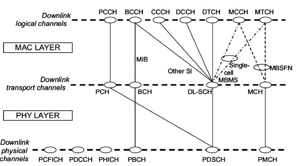
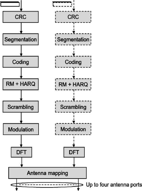
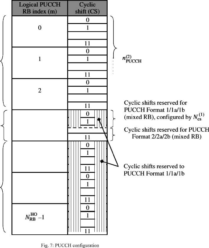
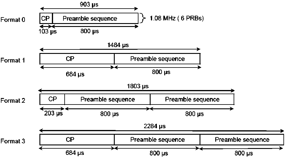
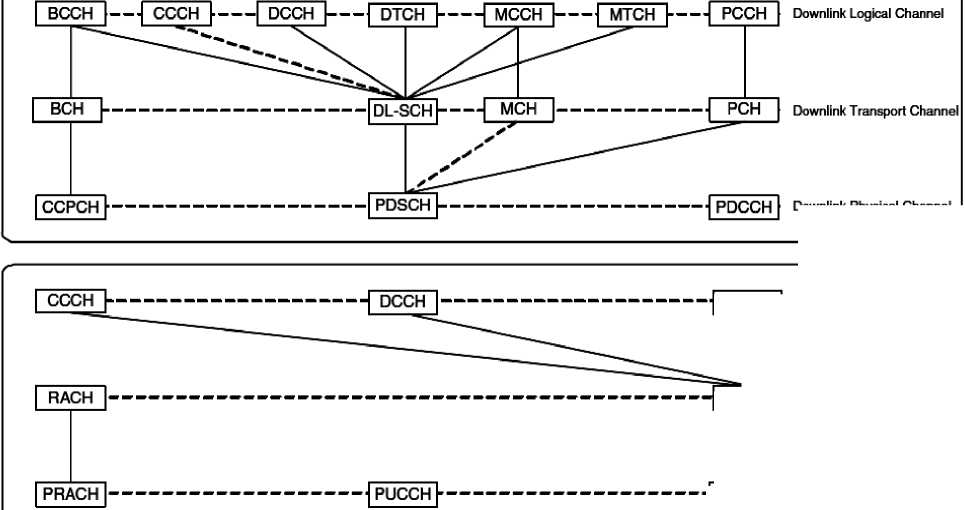
Downlink physical — "CD — PDSCH PMCH Downlink logical channels — Downlink transport channels — PCCH BCCH PCH CCCH DCCH DTCH MOCK MTCH MIB Other SI //Single- C^DMBSFN /cell xi MBMS 2" MCH BCH MAC LAYER PHY LAYER Fig. 4: Summary of downlink physical channels and mapping to higher layer IV. Uplink Physical Channels 4.1 Physical Uplink Shared Channel (PUSCH) There are three physical layer channels defined for the uplink in LTE as described below: This channel carries user data. It supports QPSK and 16 QAM modulation with 64QAM being optional. Information bits are first channel-coded with a turbo code of mother rate of 1/3 before being adapted by a rate matching process for a final suitable code rate. Adjacent data symbols are mapped to adjacent SC-FDMA symbols in the time domain before being mapped across sub-carriers. After this interleaving process, bits are scrambled before modulation mapping, DFT-spreading, sub-carrier mapping and OFDM modulation. Channel coding is similar to that of the downlink. The uplink scheduling interval is 1 ms, similar to the downlink. However, it is possible to 'bundle' a group of 4 TTIs to improve performance at cell edge and reduce higher layer protocol overhead. In this case, a MAC PDU is segmented for transmission over multiple TTIs. In the frequency domain, transmissions are allocated based on multiples of 180 kHz resource blocks. Uplink resources corresponding to the same set of sub-carriers are assigned for the two slots of a subframe. However, inter-slot frequency hopping is an option whereby different sub-carriers are used for the second slot resulting in a frequency diversity gain and averages interference providing different hopping sequences are used in neighboring cells. The PUSCH carries in addition to user data any control information necessary to decode the information such as transport format indicators and MIMO parameters. Control data is multiplexed with information data prior to DFT spreading. The PUSCH which carries data from the Uplink Shared Channel (UL-SCH), transport channel, uses DFT-Spread OFDM (DFT-S-OFDM). The transmitted processing chain is shown in Fig. 5. The information bits are first channel-coded with a turbo code of mother code rate r = 1/3, which is adapted to a suitable final code rate by a ratematching process. This is followed by symbol-level channel interleaving which follows a simple ‘timefirst’ mapping [6]. In other words, adjacent data symbols end up being mapped first to adjacent SC-FDMA symbols in the time domain, and then across the subcarriers. The coded and interleaved bits are then scrambled by a length-31 Gold code prior to modulation mapping, DFT-spreading, subcarrier mapping and OFDM modulation. The signal is frequency-shifted by half a subcarrier prior to transmission, to avoid the distortion caused by the d.c. subcarrier being concentrated in one RB. The modulations supported are QPSK, 16QAM and 64QAM (the latter being only for the highest category of User Equipment (UE)) [7]. Fig. 5: Uplink physical data channel processing Fig. 6 outlines the different steps of the UL-SCH physical-layer processing. Similar to the downlink, in the case of uplink carrier aggregation the different component carriers correspond to separate transport channels with separate physical-layer processing. Most of the uplink processing steps is outlined in Fig. 6 are identical to the corresponding steps for the downlink transport-channel processing. The different steps for the uplink transport-channel processing are summarized below. One or two transport block(s) of dynamic size delivered from the MAC layer CRC insertion per transport block Code-block segmentation including possible per-code-block CRC insertion Channel coding (Turbo coding) Rate matching and physical-layer hybrid ARQ functionality Bit-level scrambling Data modulation (QPSK, 16QAM, 64QAM) DPT pre-coding Antenna mapping Mapping to OFDM time-frequency grid for each antenna port Fig. 6: Physical layer processing for UL-SCH [4] 4.2 Physical Uplink Control Channel (PUCCH) Fig. 7 shows the logical split between different PUCCH formats and the way in which the PUCCH is configured in the LTE specifications [8]. The number of resource blocks in a slot reserved for PUCCH transmission is configured by the NHO RB -parameter. This broadcast-system parameter can be seen as the maximum number of resource blocks reserved for PUCCH while the actual PUCCH size changes dynamically based on PCFICH transmitted on downlink control channel. The parameter is used to define the frequency hopping PUSCH region. The number of resource blocks reserved for periodic Channel Quality Indicator (CQI) i.e., PUCCH Format 2/2a/2b is configured by another system parameter, N(2) RB [9]. In general it makes sense to allocate separate PUCCH resource blocks for PUCCH Format 1/1a/1b and Format 2/2a/2b. However, with narrow system bandwidth options such as a 1.4MHz case, this would lead to unacceptably high PUCCH overhead [10]. Therefore, sharing the PUCCH resources block between Format 1/1a/1b and Format 2/2a/2b users is supported in the LTE specifications. The mixed resource block is configured by the broadcasted system parameter N(1)cs , which is the number of cyclic shifts reserved for PUCCH Format 1/1a/1b on the mixed PUCCH resource block. Resources used for transmission of PUCCH formats 2/2a/2b are identified by a resource index n(2)PUCCH, which is mapped directly into a single CS resource. This parameter is explicitly signaled via UE-specific higher layer signaling. Resource blocks reserved for PUCCH Format 2/2a/2b, configured by N^ Mixed resource block: contains both Format 1/la/lb and Format 2/2a/2b resources Resource blocks reserved for PUCCH Format 1/la/lb 4.3 Physical Random Access Channel (PRACH) Random access transmission is the only nonsynchronized transmission in the LTE uplink. Although the terminal synchronizes to the received downlink signal before transmitting on RACH, it cannot determine its distance from the base station. Thus, timing uncertainty caused by two-way propagation delay remains on RACH transmissions. Appropriately designed Physical Random Access Channel (PRACH) occurs reasonably frequently, provides a sufficient number of random access opportunities, supports the desired cell ranges in terms of path loss and uplink timing uncertainty, and allows for sufficiently accurate timing estimation. Additionally, PRACH should be configurable to a wide range of scenarios, both for RACH load and physical environment. For example, LTE is required to support cell ranges up to 100 km, which translates to 667 μs two-way propagation delay, as facilitated in the timing advance signaling range in the MAC layer [11]. In a LTE frame structure type 1 Frequency Division Duplex (FDD), only one PRACH resource can be configured into a subframe. The periodicity of PRACH resources can be scaled according to the expected RACH load, and PRACH resources can occur from every subframe to once in 20 ms. PRACH transmission is composed of a preamble sequence and a preceding cyclic prefix with four different formats as shown in Fig. 8. Multiple preamble formats are required due to the wide range of environments. For example, the long CP in preamble formats 1 and 3 assists with large cell ranges in terms of increased timing uncertainty tolerance whereas repeated preamble sequences in formats 2 and 3 compensate for increased path loss. The guard period that is necessary after an unsynchronized preamble is not explicitly specified, but PRACH location in the subframe structure provides a sufficient guard period. Particular considerations are required only in very special cases. For each cell, 64 preamble sequences are configured and, thus, there are 64 random access opportunities per PRACH resource. PRACH occupies 1.08 MHz bandwidth, which provides reasonable resolution for timing estimation. Fig. 8: LTE RACH preamble formats for FDD [11] V. Communication Channel Structure Each channel is characterized with a certain set of parameters and functions. There are logical channels that are mapped to transport channels. And, there are transport channels that are mapped to physical channels. Logical channels are identified with respect to the information carried by them and transport channels are distinguished according to their transmission characteristics. Similarly, physical channels are characterized by their configuration for data protection. Fig. 9 shows the mapping structure of channels for uplink and downlink [12]. Downlink Physical Channel UL-SCH | Uplink Transport Channel ■j PUSCH~| Uplink Physical Channel Fig. 9: Downlink and uplink channel mapping j DTCH "]■ Uplink Logical Channel There are two types of logical channels: control and traffic channels. Control channels are as follows: • BCCH: Broadcast Control Channel is to transmit broadcasting system control information. • PCCH: Paging Control Channel is to transmit paging information when UE is unallocated. • CCCH: Common Control Channel is used by UE when UE has no RRC connection. • MCCH: Multicast Control Channel is used to transmit MBMS control information, which is point-to-multipoint (eNB to UEs) and only UEs that receive MBMS use it. • DCCH: Dedicated Control Channel is a point-to-point bidirectional channel used by UE for RRC connection. Traffic channels are as follows: • DTCH: Dedicated Traffic Channel is a point-to-point bidirectional channel dedicated to one UE to transfer user information. • MTCH: Multicast Traffic Channel is a point-to-multipoint channel for transmitting traffic data from the network to the UE Transport channels provide structure passing data to/from higher layers, mechanism to configure PHY, status indicators to higher layers (CQI, error, etc.) and higher-layer peer-to-peer signaling. Transport channels for downlink are as follows: • BCH: Broadcast Channel transmits entire cell area with fixed transport format. • DL-SCH: Downlink Shared Channel is used for HARQ, dynamic link adaptation, UE DRX (discontinuous receive) for power save, dynamic and semi static allocation, and beamforming. • PCH: Paging Channel is used for UE DRX, broadcast over cell coverage. • MCH: Multicast Channel provides support for Multicast Broadcast -Single Frequency Network (MB-SFN) with semi-static resource allocation. Transport channels for uplink are as follows: • UL-SCH: Uplink Shared Channel is for HARQ, dynamic link adaptation, support for UE DRX, and dynamic and semi static resource allocation with 1/3 turbo coding. • RACH: Random Access Channel is for limited control information, which has collision risk. Transport channels are connected to physical channels. LTE downlink physical channels are as follows: • PDSCH: Physical Downlink Shared Channel is utilized for data and multimedia transport. It is designed for high data rates with QPSK, 16QAM, and 64QAM modulation with 1/3 turbo coding and spatial multiplexing. • PDCCH: Physical Downlink Control Channel conveys UE-specific information with QPSK-only modulation for robustness. Up to first three OFDM symbols in the first slot of a subframe are used for PDCCH. • CCPCH: Common Control Physical Channel conveys cell information with QPSK-only modulation and convolutional coding. CCPCH is sent close to center frequency. LTE uplink physical channels are the following: • PUSCH: Physical Uplink Shared Channel is allocated subframe basis by the UL scheduler with QPSK, 16QAM, or 64QAM modulation. • PUCCH: Physical Uplink Control Channel carries uplink control information including CQI, ACK/NACK, HARQ, and uplink scheduling requests. Each physical channel has a defined algorithm for bit scrambling, modulation, layer mapping, precoding, and scheduling. It is also, noted that layer mapping and precoding are applicable when MIMO mode is present [12]. VI. Conclusions The LTE physical layer implements a number of technologies to deliver on requirements for high data rates and spectral efficiency. Aside from capacity, the physical layer is structured to provide low latency. The 1 ms subframe duration provides low latency through small scheduling intervals while maintaining low overhead related to higher layer protocols. The PHY is also well designed to provide high cell-edge performance with specific features such as dynamic bandwidth allocation to users and the design of reference signals and control channels which take into account more challenging path loss and interference environment at the cell edge. This paper discussed the main types of downlink which contains: Firstly PBCH- transmits the broadcast channel BCH. It is sent over 72 central sub-carriers on symbols 0 to 3 of slot 1, using QPSK modulation. While the second type is PCFICH-transmits the size of the PDCCH in OFDM symbols. PDCCH-specifies the transport channel format, allocates resources and HARQ information. The forth type is PHICH-acknowledges UL transmissions. PDSCH or DL-SCH -carries data to the UE (payload) and finally PMCH -carries the downlink payload. On the other hand the uplink has three main types: PRACH - contention-based random access channel, used to adjust the UE timing. It occupies 72 sub-carriers (5 RB) by 2 slots deep. Once the random access is successful, the message is transmitted in the UL-SCH. PUCCH acknowledges DL transmissions, sends CQI (Channel Quality Indicator) data, MIMO feedback and makes requests for UL transmission sand the third type is PUSCH or UL-SCH carries the UE data (payload).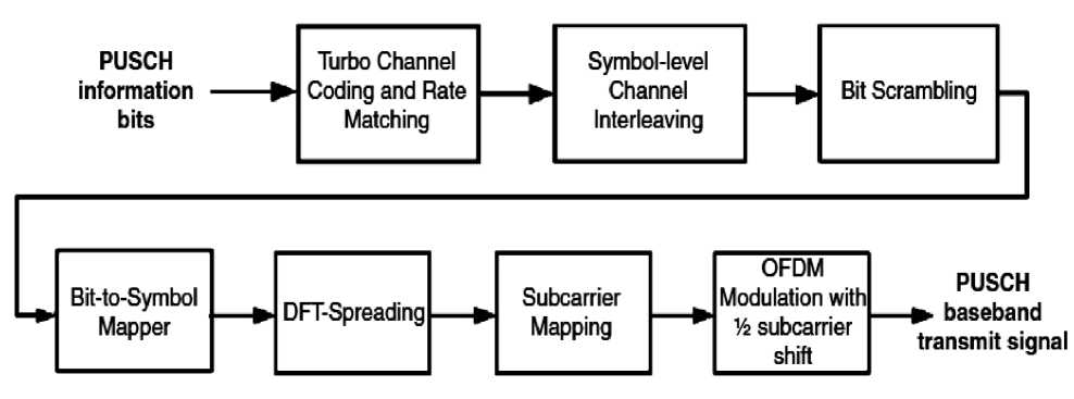
References Downlink and Uplink Physical Channels in Long Term Evolution
- 3GPP Technical Specifi cation, TS 36.211, “Evolved Universal Terrestrial Radio Access (E-UTRA); Physical channels and modulation,” 3GPP, v 8.4.0, Sep. 2008.
- 3GPP Technical Specification, TS 36.214, “Evolved Universal Terrestrial Radio Access (E-UTRA); Physical layer measurements,” 3GPP, v 8.4.0, Sep. 2008.
- L. Korowajczuk, “LTE, WiMAX and WLAN network design, optimization and performance analysis,” John Wiley, USA, pp.447-448, 2011.
- E. Dahlman, S. Parkvall, and J. Sköld., “4G LTE/LTE-Advanced for Mobile Broadband,” Elsevier, UK, pp.143-204, 2011.
- P. Lescuyer and T. Lucidarme, “Evolved Packet System (EPS) The LTE and SAE Evolution of 3G UMTS,” John Wiley, pp.124, 2008.
- Motorola, ‘R1-072671: Uplink Channel Interleaving’, www.3gpp.org, 3GPP TSG RAN WG1, meeting 49bis, Orlando, USA, June 2007.
- S. Sesia, I. Toufik and M. Baker, “LTE – the UMTS long term evolution from theory to practice”, John Wiley, UK, pp. 344, 2011.
- 3GPP Technical Specification, TS 36.211, “Evolved Universal Terrestrial Radio Access (E-UTRA); Physical channels and modulation,”’ 3GPP, v 8.4.0 Sep. 2008.
- H. Holma and A. Toskala, “LTE for UMTS evolution to LTE-Advanced,” 2nd edit, John Wiley, UK, pp.98-99, 2011.
- 3GPP Tdoc R1–080931, “ACK/NACK channelization for PRBs containing both ACK/NACK and CQI,”’ Nokia Siemens Networks, Nokia, Texas Instruments.
- H. Holma and A. Toskala, “LTE for UMTS –OFDMA and SC-FDMA based radio access,” John Wiley, UK, pp.109, 2009.
- M. Ergen, “Mobile Broadband Including WiMAX and LTE,” Springer USA, pp.393-395, 2009.
