Dynamic Modeling and H∞ Control of Offshore Wind Turbines

Author: Farzaneh Haghjoo, Mohammad Eghtesad, Ehsan Azadi Yazdi
Journal: International Journal of Engineering and Manufacturing(IJEM) @ijem
Article in issue: 1 vol.7, 2017.
Free access
In this paper, vibration control problem in tension leg platform offshore wind turbines is investigated. First a non-linear model of the wind turbine is obtained. Six degrees of freedom are considered in the model including surge, heave and pitch of the platform, tower fore-aft vibrations, rotor rotation and drivetrain torsional vibration. Moreover all external loads acting on the offshore wind turbine such as aerodynamic loads, hydrodynamic loads and mooring line forces are taken into account. To achieve an accurate model of the wind turbine, tower and drivetrain are modelled as flexible components. The model output is compared with FAST simulator; a popular open source software for modeling wind turbines. Then, a robust controller is designed to regulate rotor speed and output power, increase wind turbine efficiency and attenuate tower fore-aft vibration. The controller is implemented on the non-linear dynamic model to investigate the closed loop performance.
Offshore wind turbine, tension leg platform, robust control, H-infinity controller
Short address: https://sciup.org/15014425
IDR: 15014425
Text of the scientific article Dynamic Modeling and H∞ Control of Offshore Wind Turbines
Published Online January 2017 in MECS
Available online at
In recent years, there has been an increasing tendency to use wind energy. Deep water with the depth of more than 30m has great deal of wind power, for instance the energy potential for winds between 10 to 100 Km offshore in USA is estimated to be more than 900 GW [1]. Floating wind turbines have three main configurations: spar-buoy platform, tension leg platform (TLP) and barge platform. Tension leg platform offshore wind turbines (OWT) are the most promising type to extract wind power available in these areas [2].
Offshore wind turbines are non-linear and complex systems affected by various loads including weight, wind disturbances, gyroscopic and centrifugal forces. Moreover OWT aerodynamics is non-linear and non-uniform. Due to these reasons, mathematical models are too difficult to obtain. Despite the importance of simple models
* Corresponding author. Tel.:989177184348; fax: 07136473511
for controller synthesis, accurate models should consist of too many DOFs to involve significant dynamic phenomena [3].
There are two kinds of dynamic models used for controller synthesis in recent researches: 1) models which are simplified and consist of a few DOFs, so some physical phenomena are neglected. 2) Models which are obtained from FAST simulator. FAST models are non-linear and very complicated and computationally expensive[4]. Hence deriving a simple and accurate model suitable for controller design is still an interesting field for study.
Some researches in the field of OWT design benefit from linear modeling in frequency domain. Lee used linear hydrodynamic equations in frequency domain for computing vibration amplitude of 6 motion modes of floating platforms such as tension leg and spar buoy types [5]. Wayman et al. used the same process for analyzing 5 MW TLP and spar buoy wind turbines [6, 7].
Handerson and Patel assess 700 KW wind turbine motions and the effects of platform motions on fatigue loads by using frequency domain analysis. They showed platform motions affect generator and tower loads, but they are less effective than rotor dynamics on the captured power and the rotor loads [8]. Fulton and Withee et al. found similar results [9, 10].
Betti et al. modelled OWT as a whole rigid body with 4 DOFs including surge, heave and pitch of the platform and rotor rotation. This model is suitable for maximizing output power but it is not appropriate for goals such as blades and tower vibration attenuation. They used H control technique for rotor speed regulation [11, 12].
Jonckman deployed collective blade pitch PI gain scheduled (GS) controller on barge type platform [13]. Christiansen et al. considered misalignment between wind and wave. The main idea is to use GS LQR based on the estimation of wind speed and wave frequency [14].
Lackner implemented individual blade pitch (IBP) PID controller to reduce blades loads, however he found that this method was not as effective at reducing blade loads when compared to onshore WT [15, 16].
Erwin et al. demonstrated the effectiveness of blade pitch control experimentally. They implemented collective blade pitch control to reduce tower fore-aft vibration and the IBP control to reduce rotary parts’ loads [17].
Jafarnejadsani and Peeper modelled WT drivetrain and used L optimal control method [18].
Output power maximization and structural vibration attenuation play crucial roles in reducing electricity production costs, maintenance and increasing WT life. To achieve these objectives, controller should be synthesized based on an accurate dynamic model. The WT components that are actually flexible should be modeled as flexible components to improve recent relevant studies. One of these components is the tower that allocates a large part of production cost (depending on the installation and operation conditions, it is estimated that more than 30% of WT cost is allocated to the tower). Obviously tower vibration can be controlled and consequently manufacturing cost can be reduced by modelling tower more accurately. Drivetrain torsional vibration should also be considered to prevent its unwanted motions. So drivetrain should be modeled as a distinct flexible component.
In the first part of the paper, the non-linear model of a 5 MW tension leg platform wind turbine is derived which is appropriate for controller synthesis and implementation. The proposed model consists of 6 degrees of freedom including surge, heave and pitch of the platform, first bending mode of the tower, the rotor rotation and the drivetrain torsion. Tower and drivetrain modeled as flexible components. Control inputs are blade pitch angle and generator torque.
In the second part of the paper, H controller is designed based on the proposed model in the above rated wind speed region. In addition to the inherent robustness properties of this controller, it can reduce disturbance and noise effects on the system. In the above rated wind speed region, the wind speed is almost in the range of 10 to 22 m/s, the captured wind energy should be limited in order to avoid dangerous mechanical and electrical loads. In this study controller design is carried out with the aim of rotor speed regulation and tower vibration attenuation.
The remainder of this paper is organized as follows: in section II mathematical model of offshore wind turbine is described based on Lagrange method. Dynamic modelling simulation and their validations are presented in section III. In section IV the H control technique is introduced. Simulation results of H controller performance are presented in section V. Conclusion is given in section VI.
|
Nomenclature A nacll twr C d |
Nacelle area Tower drag coefficient |
|
nac Cd C d C q d bcpf d tc d twr mean d sbott hydrodynamic G h h ctwr h nac h pf h twr jg j r K cb k drvtrn L0 l pre l a naccx n g ovrhg r bld rotspeed v wind ρ air ρ wtr β |
Nacelle drag coefficient Platform drag coefficient Rotor torque coefficient Distance from platform centroid to the centre of buoyancy Vertical distance between platform centroid and water surface Mean tower diameter Distance between platform centroid to its bottom Hydrodynamic force Standard gravity Water height distance between tower centroid and water surface distance between nacelle centroid and water surface Platform height Tower height generator mass moment of inertia Rotor mass moment of inertia Cable stiffness coefficient Drivetrain torsion stiffness coefficient Rest length of cable Pretension cable length Distance between the hooks of tie rods Distance between nacelle and tower top Gear box ratio Horizontal distance between nacelle and rotor Blade radius Rotor speed Wind speed Air density Water density Blade pitch angle |
-
2. Wind Turbine Non-Linear Model
Dynamic equations of an OWT can be derived using Lagrange method. The equation of motion in Lagrange method is given by:
d dEkx 3Ek dEd d E p
— (—-)--- + —- + —p = Q.
dt d q i d q i d q i d q i
Where Ek, Ep and Ed are kinetic, potential and dissipated energies and q is generalized coordinate and in this system is defined as q = {xp, yp ,9p ,9t ,9T ,9]} , which are surge, heave, pitch of the platform and fore-aft tower motion, rotor rotation and low speed shaft rotation respectively. Qi is generalized loads acting on the ith generalized coordinate.
The origin of coordinate system chosen for OWT modelling, is placed in the platform centroid in static equilibrium state, which is shown in Fig.1. cp , ctwr , cN and cr are centres of the mass of the platform, tower, nacelle and rotor respectively. Position vectors of these centres of mass should be computed in the presented coordinate system. Time derivatives of these vectors are velocity vectors. Now kinetic energy and potential energy due to gravity can be described in terms of velocity and position vectors. Because of the restrictions on the length of the paper, the detailed expression of the equations of motion is omitted in this paper.
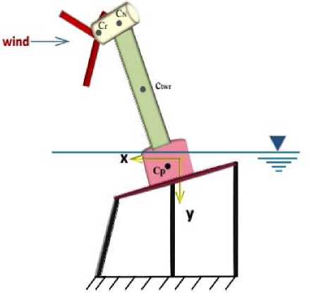
Fig.1. Coordinate System of Tension Leg Platform Offshore Wind Turbine
-
2.1. Forces and torques acting on the system
-
2.1.1. Aerodynamic model
-
2.1.1.1. Drivetrain dynamic model
In this part, external forces and torques acting on the system are described. These loads include aerodynamic and hydrodynamic loads and mooring line forces.
Aerodynamic model explains the interaction between the wind and the wind turbine. The model is expresses the thrust forces and torques acting on the drivetrain. Before explaining aerodynamic model let us derive the mathematical model of the drivetrain.
Drivetrain includes generator, high speed shaft, gearbox, low speed shaft and rotor. Drivetrain DOFs are rotor and low speed shaft rotation. A schematic representation of the drivetrain model is depicted in Fig.2.
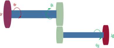
Fig.2. Wind Turbine Drivetrain
The governing equations of the drivetrain mathematical model are given by:
Taero = Jr θ r + kdrvtrn ( θ r - θ l ) + cdrvtrn ( θ r - θ l )
g g g . g . l drvtrn r l drvtrn r l
Where T is the aerodynamic load given by:
T r = 1 πρ air r bld 3 C q ( λ , β ) v rel 2
C ( λ , β ) is the torque coefficient that is a function of the tip speed ratio (λ) and the blade pitch angle (β).
Tip speed ratio shows how much faster the tip of the blades travels than the wind at the rotor hub and it is computed by:
λ = rbld θ r vrel
v is the relative wind speed at the hub, given by:
vrel =dtcθpcos(θp)+hrtrθtcos(θt)-ovhng.θtsin(θt)+xp +vwind
2.1.1.2. Thrust force
It is assumed the wind speed is the same in all points of OWT and the thrust force computed based on 1-D approach for simplicity. Thrust force acting on the rotor is computed as follows [14]:
F t =- 1 πρ air r bld 2 C t ( λ , β ) v rel 2
Where C ( λ , β ) is the thrust coefficient, a function of tip speed ratio and the blade pitch angle, derived by curvefitting of Fourier transform series on the data collected in FAST simulator. For instance, the resulting thrust coefficient curve versus tip speed ratio in the blade pitch angles of 0, 5 and 9 degree is shown in Fig.3.
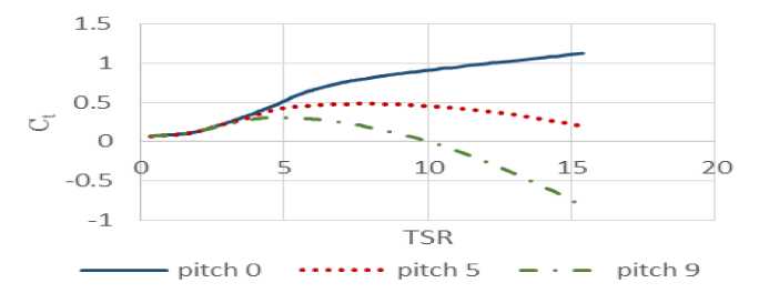
Fig.3. Thrust Coefficient Versus λ
The thrust force exerted on the tower is assumed to be a lumped force applied in the mass centre of the tower, given by:
Fitwr =-1 PC Г htwr dmeantwr ^(9) V,T + Vwind(8)
v twr is the relative wind speed in the centre of mass of the tower computed by:
^t* = dA cos(9p) + h^, cos(9) + Xp + v^(9)
Thrust force acting on the nacelle is computed as follows:
Vera = dA cos(9p)+ h„9, cos(A)+naccx9, sin(A)+xp + v^ind
-
2.1.2. Hydrodynamic model
-
2.1.2.1. Buoyancy force
Hydrodynamic model explain all forces acting on OWT due to interaction between the platform and its surrounding water. This model includes buoyancy, drag and wave forces which are described in the following sections.
According to Archimedes' principle, buoyancy force on a submerged object equals to the fluid weight which it displaces. Hence, the buoyant force as a function of time is obtained by:
Fb ( t ) = - P„fr . g . vol( t )
The volume of the submerged platform is given by:
vol = n .r pf. 2 .min((y p +h st ),h pf )
w here h is the platform height in the static equilibrium state. t he distance from the centroid of platform to the center of buoyancy force is given by:
min((y p +h st ),h pf )
' bcpf sbsbott
2.1.2.2. Hydraulic Drag and wave thrust:
Due to the variable submerged platform height, wave thrust and drag forces are derived decomposing the cylindrical platform to n sub cylinders in y direction with the same cross section. For a submerged cylinder, drag force is computed by means of Morison equation. Drag force acting on the ith sub cylinder centroid is computed by equation (15), where ^d is relative velocity between the wave and the ith sub cylinder.
FDi = - 1 Cd P A ^ rel,
Thrust force due to relative acceleration between the wave and the ith sub cylinder is given by:
F.: ( P w.r .vol+m)a i
Where m is the added mass and computed by identification in FAST simulator. Added mass is the effective increase in mass experienced by an immersed object in the fluid.
2.1.3. Moring line system
Mooring line system is made up of a series of cables connecting the platform to the sea bed. The tension in cables acts as restoring force against platform movements. It is assumed, there are three cables attached to the platform and each cable modelled as a linear spring. The pretension in each cable is calculated by solving the static equilibrium equation, cable tension is computed as follows:
f = (k сЬ , (l - l pre ) + F pre Xdi" l o ) ) (17)
Where l is the length of ith cable.
After obtaining the dynamic model of the OWT, a controller should be designed to improve the performance of the system. In this paper, control objectives are to regulate rotor speed and attenuate tower vibration in above rated wind speed region by adjusting the control inputs: generator torque and blade pitch angle {lg , в } .
In this section, a linear H controller will be design to guarantee robust asymptotic stability and achieve
control objectives. The H controller design method that is used in this work requires a linear plant. Hence, the nonlinear model of OWT is linearized in the wind speed of 11m/s for controller design purpose.
The control objectives in this paper are as follows:
-
1) Stability: the closed loop system is internally stable for nominal values of parameters.
-
2) Rotor speed regulation: to prevent excessive increase in the rotor speed, it should be limited.
-
3) Tower vibration attenuation: tower vibration should be decreased to increase stability and mechanical life of OWT structure.
Let us briefly describe the H controller synthesis method for a plant transfer function G(s) (Here, the plant transfer function is obtained by linearizing the OWT model between control inputs { Tg , в } and the controlled variables { ^,0r } ). Assume a controller transfer function K(s), sensitivity transfer function S(s) and complementary sensitivity transfer function T(s) are defined as:
5 (s) = (I+ G(s)K(s))-1 (18)
T (s) = (I + G(s)K(s)) - 1 G (s)K(s) (19)
H controller, K(s), is a stabilizing controller that is the solution of the optimization problem:
min K (s)
W 1 (s)S(s)
W ( s ) K (s)S(s)
W 3 (s)T(s)
w
Where the infinity norm is defined as the maximum singular value of the given transfer matrix and weight function W (s) is a design parameters that should be chosen carefully to achieve control objectives.
Various methods have been proposed to solve the H controller synthesis problem (26). In this paper we use the well-known linear matrix inequality (LMI) method proposed in [22]. Due to the restriction on the length of the paper the LMI method is not explained here. Instead, we briefly discuss the weight functions and their selection criteria.
One of the control objectives is to reject the effects of wind and wave disturbance on OWT system. This objective can be achieved by decreasing the gain of the transfer function between the disturbances I v „ff^^m^A and the output vector ( ^ , # 1.
wind hydrodynamic tr
Another control objective is to use actuator as little as possible. In the other words, rotor speed should be tuned to a constant value by means of small usage of blade pitch angle, and meanwhile adjust output power to its nominal value and prevent unwanted loads applied to the drivetrain and the structure. So W ( s ) K (s)S(s) is introduced to limit the actuation and W (s) T(s) is used to reject noise. Here, the weight functions are chosen by trial and error as follows:
s + 158.5
W ( s )
158.5s + 14.13
s + 31.62
1 31.62 s + 17.78 J
s
W 2 ( s )
W 3 ( s )
= < 5623 s + 8 .
” s + 0.0004417 '
_ 7.943s + 7 , s + 948.7
316.2 s + 377.7
-
4. Simulation Results
-
4.1. Dynamic model simulation and validation
In this section, Simulation results are presented. First, the dynamic model of the OWT will be simulated in open-loop. The results will be compared with the response of a similar OWT in FAST. After validating the dynamic model, controller will be designed and the closed-loop simulations will be presented.
In this part, simulation results of derived non-linear model and FAST simulator are presented. For simulating in FAST, all DOFs available in this software are enabled. Simulations are carried out in a set of variable conditions to validate simplified model. Parameters used for OWT modelling are introduced in Table 1. Descriptions of parameters are in the nomenclature section.
Table 1. Main Parameters of the Offshore Wind Turbine
|
Parameter |
value |
Parameter |
Value |
|
A nacll |
9.62 m2 |
J g |
534.116kg/m2 |
|
twr C d |
1 |
j r |
38759228kg/m |
|
nac Cd |
1 |
K cb |
1.5/l 0 GN/m |
|
d tc |
37.5503 m |
k drvtrn |
8.67637 |
|
dtwr mean |
5.085 m |
L 0 |
151.73m |
|
d sbott |
10.3397 m |
l pre |
154.3247m |
|
G |
9.80665 m/s2 |
l a |
27 m |
|
H |
200 m |
nac cx |
1.9 m |
|
hctwr |
38.234 m |
n g |
97 |
|
h nac |
89.5626 m |
ovrhg |
5.0191 m |
|
h pf |
47.89 |
r bld |
61.5 m |
|
h twr |
87.6 m |
ρ air |
1.225 kg/m3 |
|
ρ wtr |
1025 kg/m3 |
The first validation test is through constant inputs; v m^ = 11, в = 0, т = 10 kNm . Time series responses of the proposed nonlinear model versus FAST are shown in Fig.4. Responses show a similar trend for both models especially in low frequency. Note that the high frequency response is different that is not a great deal in our study because it is beyond the closed-loop bandwidth and will be vanished by the controller.
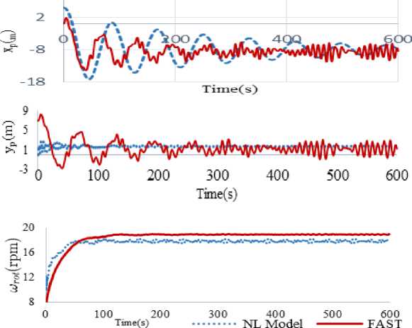
Fig.4. Comparison of the Trajectories Obtained with the Nonlinear Model (Blue Lines) and FAST (Red Lines) In v^ d = 11 m / s
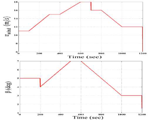
Fig.5. Wind Speed and Blade Pitch Angle Profiles
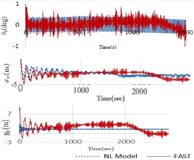
Fig.6. Comparison of the Trajectories Obtained With the Nonlinear Model (Blue Lines) and FAST (Red Lines) for Varying Input Signals
In the second validation test, wind speed and blade pitch angle are not assumed to be constant. Variations of those two parameters with time are shown in Fig.5. The simulation results of the nonlinear model and FAST are depicted in Fig.6. that shows a good agreement of two models. Errors in all DOFs are calculated and reported in table 2. According to this table errors are less than 10% in all DOFs that emphasizes the validity of the proposed nonlinear model.
Table 2. Comparison of The Results of the Simplified Model and FAST
|
Error(%) |
θ p |
Θ t |
x p |
y p |
wrot |
|
V wind =11m/s |
9.5 |
8.9 |
4.9 |
2.6 |
4.4 |
|
Variable wind speed |
9.8 |
9.7 |
2.3 |
4.7 |
1.3 |
-
4.2. Linearization of the dynamic model
-
4.3. Closed-loop simulation
As stated earlier, the H controller design method used in this work requires a linear plant. Hence, the nonlinear model of OWT is linearized in the wind speed of 11m/s for controller design purpose. It should be verified that the linearized model represents the OWT with a good precision. Simulation results of linear and non-linear models can be compared in Fig.7. According to the results, the models have similar behavior in low frequency near equilibrium point.
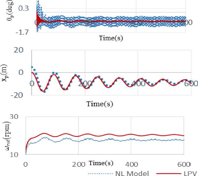
Fig.7. Comparison of No-Linear and Linear Model Results
In this section, the closed-loop system consisting of the designed H controller and the non-linear model of OWT has been studied. The wind speed profile of Fig.5 has been applied to the system. The variations in control inputs (i.e. pitch angle and generator torque) are demonstrated in Fig.8. According to these figures, the mean value of blade pitch angle is 6 degree in this study which is much lower than in [11]. The generator torque is also regulated on its nominal value of 25 kN.m. Moreover control inputs fluctuations are very small which is of great importance in OWTs.
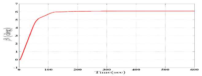
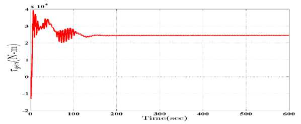
Fig.8. Control inputs :blade pitch angle , generator torque obtained using H controller
Trajectories of rotor speed, tower oscillation linear speed, pitch, surge and heave of the platform are shown in Fig.9. The proposed H controller outperforms the one in [11]. In all DOFs, fluctuations are much less than what reported in [11].
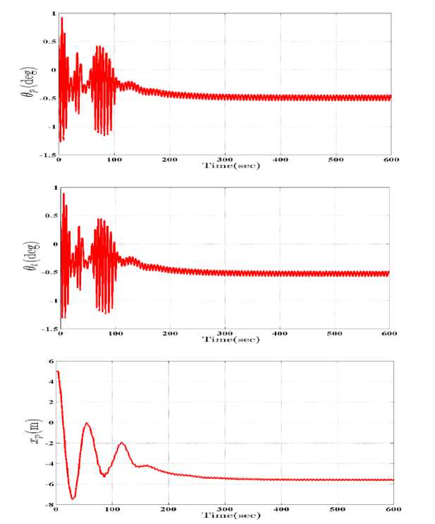
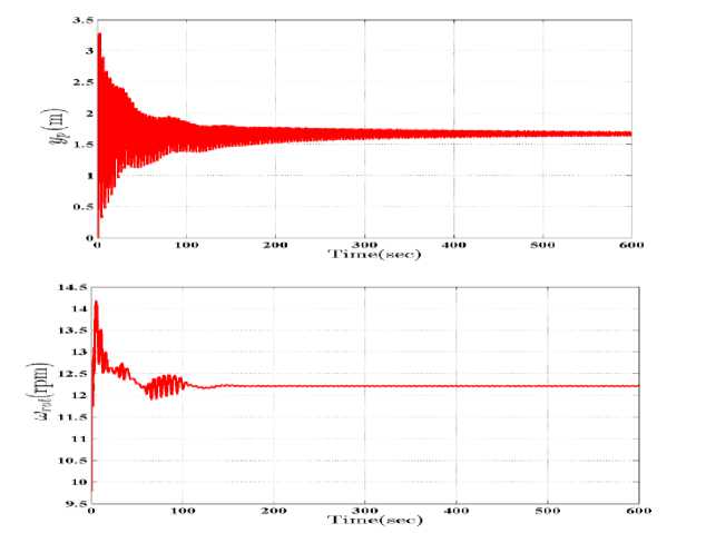
Fig.9. Time Response of all DOFs Obtained using H Controller
-
5. Conclusion
In this paper a non-linear model of tension leg platform offshore wind turbine is derived. Although this model is relatively simple and computationally inexpensive, all important physical phenomena are included in it. In the model, tower and drivetrain are modeled as flexible components, hence in total 6 DOFs including surge, heave and pitch of the platform, fore-aft tower vibration, rotor rotation and drivetrain torsion, aerodynamic, hydrodynamic loads and mooring line forces are considered; whereas previous studies have not considered these DOFs all together. The proposed model has been compared by FAST and validated. The advantage of our model over FAST model is its simplicity that makes it suitable for controller synthesis. A linear H controller is designed and implemented on the non-linear dynamic model in order to regulate rotor speed, attenuate tower fore-aft vibration and reduce variations in control input. The closed-loop simulations show a good performance that outperforms previous results.
-
[3] Bobanac, V., Jelavić, M., & Perić, N. (2010, September). Linear parameter varying approach to wind turbine control. In Power Electronics and Motion Control Conference (EPE/PEMC), 2010 14th International (pp. T12-60). IEEE.
-
[4] J. Jonkman and B. Marshal, “FAST User’s Guide,” Nat.Ren.En.Lab., Golden, CO,USA, Tech.Rep. NREL/TP-500-38230, 2005.
-
[5] K. H. Lee, "Responses of floating wind turbines to wind and wave excitation," Massachusetts Institute of Technology, 2005.ASME, 2003. ASME Manual MS-4, An ASME Paper, latest ed. The American Society of Mechanical Engineers, New York. See also URL http://www.asme.org/pubs/MS4.html .
-
[6] E. Wayman, P. Sclavounos, S. Butterfield, J. Jonkman, and W. Musial, "Coupled dynamic modeling of floating wind turbine systems," in Offshore Technology Conference, 2006.
-
[7] E. N. Wayman, "Coupled dynamics and economic analysis of floating wind turbine systems," Massachusetts Institute of Technology, 2006.
-
[8] A. R. Henderson and M. H. Patel, "On the modelling of a floating offshore wind turbine," Wind Energy, Vol. 6, pp. 53-86, 2003.
-
[9] G. R. Fulton, D. J. Malcolm, and E. Moroz, "Design of a semi-submersible platform for a 5MW wind turbine," in Proceedings 44th AIAA/ASME Wind Energy Symposium, Reno NV January, 2006, pp. 912.
-
[10] J. E. Withee, "Fully coupled dynamic analysis of a floating wind turbine system," Monterey, California. Naval Postgraduate School, 2004.
-
[11] G. Betti, M. Farina, G. A. Guagliardi, A. Marzorati, and R. Scattolini, "Development of a control-oriented model of floating wind turbines," Control Systems Technology, IEEE Transactions on, Vol. 22, pp. 69-82, 2014.
-
[12] G. Betti, M. Farina, A. Marzorati, R. Scattolini, and G. Guagliardi, "Modeling and control of a floating wind turbine with spar buoy platform," in Energy Conference and Exhibition (ENERGYCON), 2012 IEEE International, 2012, pp. 189-194
-
[13] J. M. Jonkman, " Dynamics modeling and loads analysis of an offshore floating wind turbine" , ProQuest, 2007.
-
[14] S. Christiansen, T. Bak, and T. Knudsen, "Damping wind and wave loads on a floating wind turbine," Energies , Vol. 6, pp. 4097-4116, 2013.
-
[15] M. A. Lackner, "An investigation of variable power collective pitch control for load mitigation of floating offshore wind turbines," Wind Energy , Vol. 16, pp. 519-528, 2013.
-
[16] M. A. Lackner, "Controlling platform motions and reducing blade loads for floating wind turbines," Wind Engineering , Vol. 33, pp. 541-554, 2009.
-
[17] E. A. Bossanyi, P. A. Fleming, and A. D. Wright" ,Validation of individual pitch control by field tests on two-and three-bladed wind turbines," Control Systems Technology, IEEE Transactions on, Vol. 21, pp. 1067-1078, 2013
-
[18] H. Jafarnejadsani and J. Pieper, "Gain-Scheduled li-Optimal Control of Variable-Speed--Variable-Pitch Wind Turbines," 2015.
-
[19] Bossanyi, E. A. (2003). Wind turbine control for load reduction. Wind energy , 6 (3), 229-244.
-
[20] Johnson, K. E., Pao, L. Y., Balas, M. J., & Fingersh, L. J. (2006). Control of variable-speed wind
turbines: standard and adaptive techniques for maximizing energy capture. Control Systems, IEEE , 26 (3), 70-81.
-
[21] Butterfield, S., Musial, W., & Scott, G. (2009). Definition of a 5-MW reference wind turbine for offshore system development. Golden, CO: National Renewable Energy Laboratory. Bianchi, F. D., De Battista, H., & Mantz, R. J. (2006). Wind turbine control systems: principles, modelling and gain scheduling design. Springer Science & Business Media.
-
[22] Scherer, C., Gahinet, P., & Chilali, M. (1997). Multiobjective output-feedback control via LMI optimization. IEEE Transactions on automatic control, 42(7), 896-911.


Farzaneh Haghjoo : was born on December 8, 1989 in Shiraz, Iran. She received the B.Sc degree and the M.Sc degree in mechanical engineering from Shiraz university, Shiraz, Iran in 2013 and 2016 respectively. Now her research interest include robust control, modeling and control of offshore wind turbines.
Ehsan Azadi Yazdi received the B.S., M.S., and Ph.D. degrees from the Department of Mechanical Engineering at Shiraz University, Iran, in 2005, at Sharif University of Technology, Iran, in 2007, and at the University of British Columbia, Vancouver, Canada, in 2011, respectively. He is currently an Assistant Professor at the School of Mechanical Engineering, Shiraz University. His research interests include robust and hybrid control, nonsmooth optimization, hard disk drive servo, and machine tool control. Dr. Azadi Yazdi is a recipient of the Best Paper Award in 23rd Canadian Congress of Applied Mechanics in
2011. He is the director of the Technology Incubator of Fars Science and Technology Park.
Mohammad Eghtesad received his B.Sc. from University of Tehran (1983), M.Sc. from University of Tehran (1987) and Ph.D. from University of Ottawa (1996). He joined the School of Mechanical Engineering at Shiraz University in 1997 where he is currently a full Professor. He has taught and done research in the area of robotics, mechatronics and control. His research includes both theoretical and experimental studies. Since 2012 he is the editorin-chief of Iranian Journal of Science and Technology, Transactions of Mechanical Engineering.
References Dynamic Modeling and H∞ Control of Offshore Wind Turbines
- P. Pardalos, S. Rebennack, M. V. Pereira, N. A. Iliadis, and V. Pappu, Handbook of Wind Power Systems: Springer, 2014.
- Bachynski, E. E., & Moan, T. (2012). Design considerations for tension leg platform wind turbines. Marine Structures, 29(1), 89-114.
- Bobanac, V., Jelavić, M., & Perić, N. (2010, September). Linear parameter varying approach to wind turbine control. In Power Electronics and Motion Control Conference (EPE/PEMC), 2010 14th International (pp. T12-60). IEEE.
- J. Jonkman and B. Marshal, "FAST User's Guide," Nat.Ren.En.Lab., Golden, CO,USA, Tech.Rep. NREL/TP-500-38230, 2005.
- K. H. Lee, "Responses of floating wind turbines to wind and wave excitation," Massachusetts Institute of Technology, 2005.ASME, 2003. ASME Manual MS-4, An ASME Paper, latest ed. The American Society of Mechanical Engineers, New York. See also URL http://www.asme.org/pubs/MS4.html.
- E. Wayman, P. Sclavounos, S. Butterfield, J. Jonkman, and W. Musial, "Coupled dynamic modeling of floating wind turbine systems," in Offshore Technology Conference, 2006.
- E. N. Wayman, "Coupled dynamics and economic analysis of floating wind turbine systems," Massachusetts Institute of Technology, 2006.
- A. R. Henderson and M. H. Patel, "On the modelling of a floating offshore wind turbine," Wind Energy, Vol. 6, pp. 53-86, 2003.
- G. R. Fulton, D. J. Malcolm, and E. Moroz, "Design of a semi-submersible platform for a 5MW wind turbine," in Proceedings 44th AIAA/ASME Wind Energy Symposium, Reno NV January, 2006, pp. 9-12.
- J. E. Withee, "Fully coupled dynamic analysis of a floating wind turbine system," Monterey, California. Naval Postgraduate School, 2004.
- G. Betti, M. Farina, G. A. Guagliardi, A. Marzorati, and R. Scattolini, "Development of a control-oriented model of floating wind turbines," Control Systems Technology, IEEE Transactions on, Vol. 22, pp. 69-82, 2014.
- G. Betti, M. Farina, A. Marzorati, R. Scattolini, and G. Guagliardi, "Modeling and control of a floating wind turbine with spar buoy platform," in Energy Conference and Exhibition (ENERGYCON), 2012 IEEE International, 2012, pp. 189-194.
- J. M. Jonkman, "Dynamics modeling and loads analysis of an offshore floating wind turbine", ProQuest, 2007.
- S. Christiansen, T. Bak, and T. Knudsen, "Damping wind and wave loads on a floating wind turbine," Energies, Vol. 6, pp. 4097-4116, 2013.
- M. A. Lackner, "An investigation of variable power collective pitch control for load mitigation of floating offshore wind turbines," Wind Energy, Vol. 16, pp. 519-528, 2013.
- M. A. Lackner, "Controlling platform motions and reducing blade loads for floating wind turbines," Wind Engineering, Vol. 33, pp. 541-554, 2009.
- E. A. Bossanyi, P. A. Fleming, and A. D. Wright, "Validation of individual pitch control by field tests on two-and three-bladed wind turbines," Control Systems Technology, IEEE Transactions on, Vol. 21, pp. 1067-1078, 2013.
- H. Jafarnejadsani and J. Pieper, "Gain-Scheduled ℓ₁-Optimal Control of Variable-Speed--Variable-Pitch Wind Turbines," 2015.
- Bossanyi, E. A. (2003). Wind turbine control for load reduction. Wind energy,6(3), 229-244.
- Johnson, K. E., Pao, L. Y., Balas, M. J., & Fingersh, L. J. (2006). Control of variable-speed wind turbines: standard and adaptive techniques for maximizing energy capture. Control Systems, IEEE, 26(3), 70-81.
- Butterfield, S., Musial, W., & Scott, G. (2009). Definition of a 5-MW reference wind turbine for offshore system development. Golden, CO: National Renewable Energy Laboratory. Bianchi, F. D., De Battista, H., & Mantz, R. J. (2006). Wind turbine control systems: principles, modelling and gain scheduling design. Springer Science & Business Media.
- Scherer, C., Gahinet, P., & Chilali, M. (1997). Multiobjective output-feedback control via LMI optimization. IEEE Transactions on automatic control, 42(7), 896-911.
