Effects of Superstrate on Electromagnetically and Gap Coupled Patch Antennas

Author: Ravindra Kumar Yadav, Jugul Kishor, R. L. Yadava
Journal: International Journal of Wireless and Microwave Technologies(IJWMT) @ijwmt
Article in issue: 3 Vol.4, 2014.
Free access
In this paper the effects of water loading (termed as superstrate) on the characteristics of an electromagnetically (EM) and coupled pentagonal patch antennas operating in the ISM band have been described. The proposed antenna structures are analyzed using HFSS and the influence of the superstrate on resonant frequency, bandwidth, VSWR and radiation characteristics have also been analyzed. The obtained results also reveal that a larger bandwidth can be found in case the dielectric substrate is separated by air gap spacing. In addition, though impedance matching is little deteriorated due to loading, however the operating frequency band (BW) shifted to lower side significantly.
Electromagnetically coupled (EMC), electromagnetically gap coupled (EMGC), microstrip patch antenna, stacked antenna, pentagonal patch antenna
Short address: https://sciup.org/15012869
IDR: 15012869
Text of the scientific article Effects of Superstrate on Electromagnetically and Gap Coupled Patch Antennas
Published Online October 2014 in MECS
Available online at
However, the effects of a water as superstrate on the centre frequency and bandwidth of electromagnetic coupled and gap coupled pentagonal patch antenna have not yet studied though both structures shows significant alteration in their performances. Therefore, authors have made an attempt to investigate and describe the effects of the water layers on the surface of the electromagnetically and gap coupled probe fed pentagonal antennas.
In general the major advantages of a pentagonal patch antenna over the rectangular patch antenna that, it supports both linear and circular polarizations [14]. The pentagonal patch antenna provides circular polarization with only one feed where as rectangular patch antenna requires multiple feeds to get circular polarization. Hence a probe fed pentagonal antennas is chosen here for study because of its better impedance matching. The pentagonal antenna size calculations were done considering the invariance of the electrostatic energy below the pentagonal and circular patches, however maintaining their areas remain constant. Fig. 1 shows the geometry of a regular pentagonal shape, however the design specifications are given in Table 1.
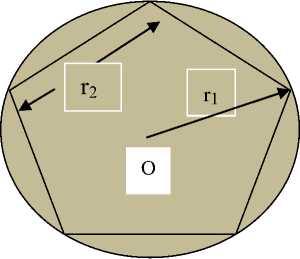
Fig. 1 Geometry of a regular pentagonal shape
The relationship between the circles ( r 1 ) to the side arm of the regular pentagon ( r 2 ) is given in equation (1).
2 r2
n r
2.37
Side arm of the pentagon ( r2 ) = 1.175 r1
In the derivation of the equation (1), the pentagonal patch is assumed to be a resonant cavity with perfectly conducting side walls. Because a circular disc is the limiting case of the polygon with large number of sides, in this case number of sides are 5. The resonant frequency of the dominant as well as for the higher order modes can be calculated from the formula given below [15]:
fnp=
X ′ np c
2 π r ε r
Where X′ np are the zeros of the derivative of the Bessel function J n (x) of the order n , as is true for TE mode circular waveguides, however for the lowest order modes;
X′np=1.84118
Table 1. Design parameters of the proposed antennas
|
Parameters |
Electromagnetically coupled antenna |
EMC gap coupled antenna (gap size,d =0.4 mm) |
|
Designed frequency (GHz) |
2.39 |
2.41 |
|
Substrate 1(FR-4) |
ε r1 = 4.4, tanδ = 0.02, h 1 =0.8 mm |
ε r1 = 4.4, tanδ = 0.02, h 1 =0.8 mm |
|
Size of the pentagon ( l 1 =l 2 ) |
28.52 mm |
28.52 mm |
|
Substrate 2(Plexiglas) |
ε r2 = 3.4, tanδ = 0.001, h 2 =0.8 mm |
ε r2 = 3.4, tanδ = 0.001, h 2 =0.8 mm |
|
Dielectric cover(Water) |
ε r = 81, tanδ = 0.0 |
ε r = 81, tanδ = 0.0 |
|
Feed location |
9.0 mm from the centre |
9.0 mm from the centre |
-
2.2. Design of electromagnetically coupled patch antenna geometry
h2, Sr2, hi, £ri,
Y
Fig. 2a Schematic diagram of electromagnetically coupled patch antenna
Water h2, Sr2, hi, £ri,
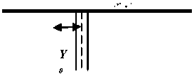
Fig. 2b Schematic diagram of electromagnetically coupled patch antenna with dielectric cover (water layer)
However the photograph of fabricated electromagnetic coupled patch antenna surface with feed line and pentagonal patch antenna are shown in Fig.3.
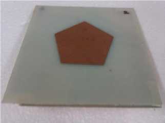
Fig. 3 Structure of electromagnetically coupled patch antenna fed with coaxial feed
-
2.3. Design of electromagnetically gap coupled antenna geometry
The geometry of the electromagnetic gap coupled patch antennas are shown in Fig. 4a &b. The dimension of the side arm of the pentagonal patch antenna is l1 and l2 . The thickness of the lower substrate is h1 and the permittivity is εr1 while h2 and εr2 are the substrate thickness and permittivity of the upper patch respectively. The two patches are also separated by an air gap having a distance of d that can be adjusted to 0.4 mm.
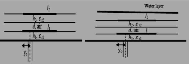
(a) (b)
Fig. 4(a) Schematic diagram of electromagnetically gap coupled Fig. 4 (b) Schematic diagram of electromagnetically gap patch antenna coupled patch antenna with water layer
However the photograph of fabricated electromagnetic gap coupled patch antenna surface with feed line are shown in Fig. 5.
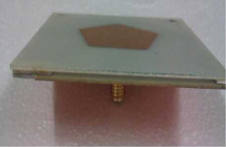
Fig. 5 Fabricated prototype of electromagnetically gap coupled patch antenna
-
3. Results and Discussions
The results of observed return loss (dB) against frequency over the operating band of the EM coupled antenna are plotted in Fig. 6 in which t = 0 represents an antenna without any layer while t = 0.1,0.2 and 0.3 mm represents the thickness of the water layer poured on the patch surface. It can be observed from this figure that there is change in return loss over the entire frequency band due to the change in the water layer superstrate thickness (0.1 mm to 0.3 mm). However, the centre frequency and the bandwidth are also slightly changed. So, we can conclude that EM coupled antennas loaded with dielectric superstrate like water, which has very high dielectric constant, show relative change in the resonant frequency. The obtained results are also summarised in Table 2. A network analyser is used for measurements of the S-parameter and the measured results are in excellent agreements with the simulated results, which is shown in the Fig. 6 and summarized in Table 3. From the Fig. 7, it is observed that, though impedance matching is little deteriorated, the operational frequency band will be slightly changed.
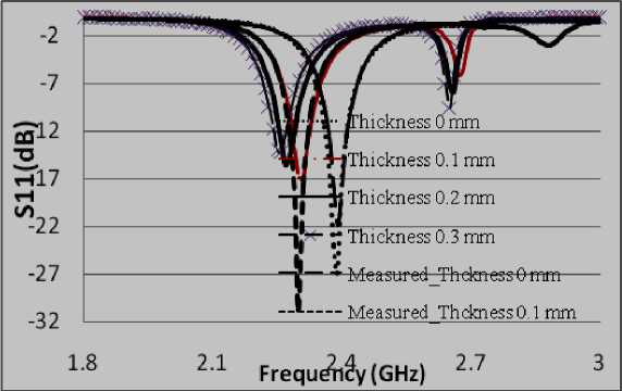
Fig. 6 Comparisons of return loss characteristics of the electromagnetically coupled patch antenna
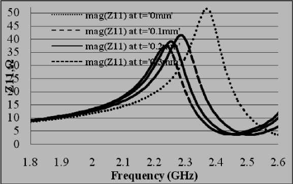
Fig. 7 Comparisons of Input Impedance EM Coupled patch antenna
Table 2 Simulated parameters of the proposed electromagnetically coupled patch antenna
|
Types |
Electromagnetically coupled antenna |
|||
|
Without dielectric cover |
With dielectric cover |
|||
|
t = 0.1 mm |
t = 0.2 mm |
t = 0.3 mm |
||
|
Designed frequency (GHz) |
2.39 |
2.3 |
2.27 |
2.26 |
|
Return loss(dB) |
-26.83 |
-16.84 |
-15.54 |
-14.2 |
|
Impedance (Ω) |
47.15 |
40.06 |
37.12 |
33.9 |
|
VSWR |
1.095 |
1.335 |
1.401 |
1.484 |
|
BW (MHz) |
62.3 |
53.8 |
48.8 |
47.2 |
|
Gain |
0.89208 |
1.1577 |
--- |
--- |
|
Radiated Power(mW) |
19.408 |
116.14 |
--- |
---- |
Table 3 Measured parameters of the proposed electromagnetically coupled patch antenna
|
Types |
Electromagnetically coupled antenna |
|
Without dielectric With dielectric cover with cover thickness t = 0.1 mm |
|
|
Designed frequency (GHz) Return loss(dB) Band Width(MHz) |
2.39 2.3 -21.90 -30.80 60 60 |
The results of EM gap coupled antenna also reveals that return loss (dB) against frequency over the operating band of the antenna are plotted in Fig. 8 in which t = 0 represents an antenna without any layer while t = 0.1,0.2 and 0.3 mm are the thickness of the water layer poured on the patch surface. It can be observed from this figure that there is change in return loss over the entire frequency band due to the change in the water layer superstrate thickness (0.1 mm to 0.3 mm). The variation of the resonant frequency of the antenna can be explained by the variation of the effective permittivity with accumulation of the water level on the surface of the antenna. The obtained results are also summarised in Table 4 which shows that the accumulation of the water level on the surface of the patch antenna reduces the antenna parameters such as return loss, impedance, VSWR, etc. A network analyser from Agilent Technologies™ is used for measurements and the measured results are slightly different from simulated results, which is shown in the Fig. 8 and summarized in Table 5. The difference in the measure and simulated result are minimized by accurate measurement of water layer thickness on the patch surface and by uniform distribution of water layer on the patch surface. From the Fig. 9, it is observed that, though impedance matching is little deteriorated, the operating frequency band will be slightly changed.
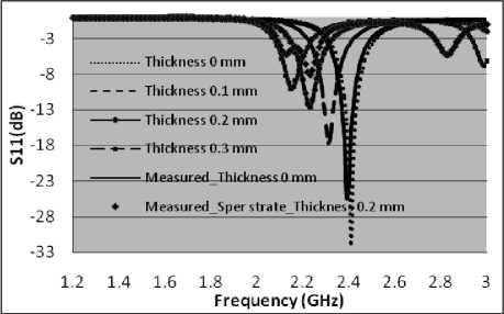
Fig. 8 Comparisons of return loss characteristics of the electromagnetically gap coupled patch antenna
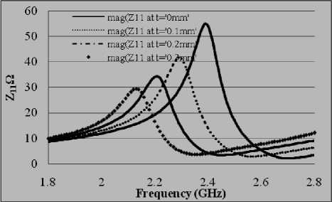
Fig. 9 Comparison of Input Impedance of electromagnetically gap coupled patch antenna
Table 4 Simulated parameters of the proposed electromagnetically gap coupled patch antenna
|
Types |
Electromagnetically coupled antenna |
|||
|
Without dielectric cover |
With dielectric cover |
|||
|
t = 0.1 mm |
t = 0.2 mm |
t = 0.3 mm |
||
|
Designed frequency (GHz) |
2.39 |
2.3 |
2.27 |
2.26 |
|
Return loss(dB) |
-26.83 |
-16.84 |
-15.54 |
-14.2 |
|
Impedance (Ω) |
47.15 |
40.06 |
37.12 |
33.9 |
|
VSWR |
1.095 |
1.335 |
1.401 |
1.484 |
|
BW (MHz) |
62.3 |
53.8 |
48.8 |
47.2 |
|
Gain |
0.89208 |
1.1577 |
--- |
--- |
|
Radiated Power(mW) |
19.08 |
116.14 |
--- |
---- |
Table 5 Measured parameters of the proposed electromagnetically Gap coupled patch antenna
|
Types |
Electromagnetically Gap coupled antenna Without With dielectric cover with dielectric thickness t = 0.1 mm cover |
|
Designed frequency (GHz) Return loss(dB) |
2.39 2.23 -25.3 -8.1 |
|
BW(MHz) |
70 0 |
-
4. Conclusion
The behaviour of the EM couple and EM gap coupled patch antenna operating in ISM band due to the formation of a water layer superstrate on its surface is investigated. It is found that the bandwidth remains practically unaffected due to rain water accumulation on the patch surface. However, the exact value of return loss, at any particular frequency within the bandwidth, undergoes change which needs to be taken into account during system design. Analysis also shows that for t = 0.3 mm, antenna structure totally stops responding as bandwidth is almost goes zero. So, one may conclude that accumulation of rain water on the top of the antenna surface (EM coupled and EM gap coupled) makes them prone to frequency shift as well as impedance mismatch. So effects of environmental conditions should be taken into account during the design phase of an antenna. If due care is not taken during the design phase, the system may fail to respond as per requirement.
Acknowledgment
The authors express their appreciation to Dr. B. K. Kanaujia, Professor, Department of Electronics and Communication, Ambedkar Institute of Technology, New Delhi for allows us to use HFSS simulation software and experimentations
References Effects of Superstrate on Electromagnetically and Gap Coupled Patch Antennas
- Inder J. Bahl, Prakash Bhartia, Stanislaw S. Stuchly, "Design of microstrip antennas covered with a dielectric layer," IEEE Transactions on antennas and propagation, vol. 30, no. 2, pp. 314 –318, March 1982.
- Rajeev R. Wakodkar, Bhaskar Gupta and Samik Chakraborty, "Variation of resonant frequency of a rectangular microstrip patch antenna due to accumulation of water over its surface," International conference on applications of electromagnetism and student innovation competition awards (AEM2C 2010), pp. 239 – 243,August 2010.
- Bhattacharyya and T. Tralman, "Effects of dielectric superstrate on patch antennas," Electronics Letters, vol. 24, no. 6, pp. 356 – 358, March 1988.
- J. Pribetich R. Ledee P. Kennis P. Pribetich M. Chive, "Modelling of microstrip antenna with dielectric protective layer for lossy medium," Electronics Letters, vol. 24 no. 23, pp. 1464 – 1465, Nov. 1988.
- O. M. Ramahi and Y. T. Lo, "Superstrate effect on the resonant frequency of microstrip antennas," Microwave and Optical Technology Letters, vol. 5, pp. 254 – 257, June 1992.
- A. K. Verma et. al., " Analysis of rectangular patch antenna with dielectric cover," IEICE Trans E74, 1991, pp.1270-76
- Q. Rao and T. A. Denidni, "Electromagnetically coupling fed broadband microstrip antennas," IEEE AP-S International symposium on antennas and propagation, Honolulu, Hawaii, USA, June 10-15, 2007.
- S. B. Deosarkar and, A. B. Nandgaonkar, "Design of high gain two-layer electromagnetically coupled patch antenna in the ISM band," International conference on electromagnetic in advanced applications (ICEAA 07), Torino Italy, September 2007.
- Ikeda, "Enhanced bandwidth enhancement of a low-profile microstrip antenna electromagnetically coupled with a folded inverted L-shaped probe," Antenna technology: small antennas and novel metamaterials, International workshop, pp. 151 – 154, 2008.
- R.Q. Lee, K. F. Lee and J. Bobinchak, "Experimental study of the two-layer electromagnetically coupled rectangular patch antenna," Antennas and Propagation, IEEE Transactions, Vol.38, No. 8, pp. 1298-1302, August 1990.
- R.Q. Lee, K. F. Lee and J. Bobinchak, "Characteristics of a two-layer electromagnetically coupled rectangular patch antenna," Electronics Letters, Vo1.23, No.20, pp. 1070-1072, 1987.
- R. Q. Lee, A. J. Zaman and K. F. Lee, "Effects of dielectric superstrates on a two-layer electromagnetically coupled patch antenna," IEEE @1989, 28/5, pp. 620-623, 1989.
- F. R. Cooray and J. S. Kot, "Analysing radiation from a cylindrical-rectangular microstrip patch antenna loaded with a superstrate and an air gap, using the electric surface current model," CSIRO ICT Centre, P. O. Box 76, Epping, NSW 1710, Australia, 2006.
- M. T. Torres et al., "Pentagonal microstrip antenna equivalent to a circular microstrip antenna for GPS operation frequency," Memorias del 7º Congreso Internacional de Cómputo en Optimization Software, CICOS 09. UAEM, Cuernavaca, Morelos, México. pp. 200-208, 2009.
- G. Kumar and K.P. Ray, "Broadband microstrip antennas," Artech House Publishers, London, 2003.
- Ji-jun Wang, Zhi-pan Zhu, "A Composite Heterostructure Mesh-shaped Patch Antenna Based on Left Handed Material," International Journal of Wireless and Microwave Technologies (IJWMT), Vol. 4, No. 1, pp. 10-19 January 2014.
- Omrane NECIBI, Abdelhak FERCHICHI, Tan-phu VUONG, Ali GHARSALLAH,"A Discussion of a 60GHz Meander Slot Antenna for an RFID TAG with Lumped Element", IJWMT, vol.4, no.2, pp.1-11, 2014.DOI: 10.5815/ijwmt.2014.02.01.
