Electric traction drive

Author: Belousov E.V., Kinas S.I., Khusainov Sh.N., Kruglov G.A.
Journal: Вестник Южно-Уральского государственного университета. Серия: Энергетика @vestnik-susu-power
Section: Электромеханические системы
Article in issue: 2 т.15, 2015.
Free access
The paper considers electric traction drive with the field regulated reluctance machine (FRRM). The FRRM principles of operation and main advantages compared with asynchronous machine and synchronous reluctance machine are presented, disadvantages are marked. Mathematical model of the drive with FRRM is described; adequate accuracy is proved by the statistical data processing. The paper presents electric drive operating point determination in the static mode, transient model analysis, which takes into account electrical, electromechanical and mechanical processes of electric traction drive, present the first stage of optimization. The second step explains a method of increasing the maximum speed of the drive. The third stage is associated with optimization of FRRM features with over-torque. Therefore, the drive is obtained with improved weight and dimension characteristics, overload capacity, which meets the requirements of the haulers. Weight-size parameters optimization, three-stage characteristics optimization estimate the most favorable parameters of the control system and the motor. The explanatory drawings are given in the article.
Electric traction drive, field regulated reluctance machine, mathematical model, weight-size parameters optimization
Short address: https://sciup.org/147158305
IDR: 147158305 | UDC: 62-83:621.313.3 | DOI: 10.14529/power150206
Тяговый электропривод
Рассматривается тяговый электропривод с синхронной реактивной машиной с независимым управлением по каналу возбуждения (СРМНВ). Представлены принцип работы и основные преимущества СРМНВ по сравнению с асинхронной машиной и синхронной реактивной машиной, отмечены недостатки. Описана математическая модель электропривода с СРМНВ, доказана ее адекватность статистической обработкой данных. Три этапа оптимизации массогабаритных показателей определяют наилучшие параметры системы управления и двигателя. Определение рабочей точки электропривода в статике, исследование переходных процессов на модели, учитывающей электрические, электромеханические и механические процессы тягового электропривода, представили первый этап оптимизации. На втором этапе пояснен способ увеличения максимальной скорости привода. Третий этап оптимизации связан с особенностями СРМНВ при перегрузках по моменту. Таким образом, получен электропривод с улучшенными массогабаритными показателями и перегрузочной способностью, который отвечает требованиям, предъявляемым к тяговым устройствам. В статье приведены поясняющие иллюстрации.
Text of the scientific article Electric traction drive
Electric traction drive is the critical part of the equipment of all electric or hybrid haulers. It imposes wide range of requirements to the power facilities, control system parameters and output performance of the full electromechanical complex. As hauler drives often work in extreme mode, it is necessary to form energy efficiency criteria of the drive in another way [1, 2].
The existing solutions of the electric drives on the base of asynchronous motor or synchronous reluctance machine ( SynRM ) do not meet such requirements. Asynchronous motors have the optimized construction, winding performance, insulation materials and power supply. Nevertheless, the overload indexes are not high. Increasing the current loading and sophisticating the SynRM construction can provide the rated torque equal to 1.1 of the asynchronous drive rated torque.
Ample scientific works [3–6] are connected with optimization of the electromechanical converter. However, the proposed solutions are oriented to the bridge m -phase inverters supply with the limited number of phases.
The new approach to the electric drive designing provides for improving overload and weight-size ratings . The “valve-inverter – motor” complex optimization would be made with due account for special electric traction drive requirements as high overload usage possibility (e.g. for overtaking or for starting with heavy cargo); as minimal dimensions (e.g. for urban electric transport with low floor for convenient passenger drop-off and pick-up), by the example of the field regulated reluctance machine ( FRRM ).
Concept and operating principles of the FRRM
FRRM is the synchronous reluctance machine where the stator winding can behave as field winding if the coil is over the interpolar space and it is a full pitch winding. Such drive works as the inversed DC machine. Stator windings can be fed by the independent sources or by the traditional multiphase controlled power converters, e.g. based on the full bridge circuit.
As the rotor may be done massive, high mechanical stiffness of the shaft can be achieved. Motor can be made in the same stator housing as the induction motor, and applying the same stator line current load FRRM develops torque greater by 20…35 %. By virtue of intentional true neutral plane displacement to the pole edge, the motor can produce overload torque up to 4…10 rated values [7–9].
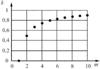
Fig. 1. Electromagnetic torque ripple rate as a function of number of phases of the FRRM
However, these values would be decreased with decreasing number of phases of the machine. The electromagnetic torque ripples are coming out. The ripple rate as a function of the number of phases is shown on fig. 1. Increase of number of phases results
Электромеханические системы in increase in the number of power semiconductor switches and the complex cost. The trade-off according to the economical, mass-weight, energy indexes is to use the six-phase machine.
Optimization of electric drive dynamic and technological parameters
Thyristor converters have 3…5 ms time delay due to thyristor groups change-over. This aggravates dynamic indexes of phase current control loop. In order for taking this problem away, it is desired to use transistor converter instead of thyristor converter. It to improve dynamic parameters of the drive with 2…16 kHz PWM.
Another weakness of the drive in respect to the technological process is the lost motion in the mechanical transmission. Steep edge of the current, huge impact stresses lead to the early mechanical failure of the equipment. The preload made by the control system of the drive solves this problem.
Mathematical model of electric drivewith the FRRM
The optimization of weight-size parameters of the electric drive was made on the base of mathematical model [6, 10–16].
The proposed model was used for mathematical description of the processes proceeded in the electromechanical complex. It allowed description of the system under normal conditions, and what is more essential – under overloads. Geometric model of the electromechanical converter was made in SolidWorks ; it reduced the time of the data processing stage.
The magnetic system calculation was made in ANSYS Maxwell module. The control system was realized in ANSYS Simplorer . The connection between the program modules was carried out by the data exchange settings in the real time mode. If the calculation of the magnetic system was made for the given point, a data vector was sent to the control system module. The control response vector was formed according to ANSYS Simplorer calculation results. Then this vector was transferred to ANSYS Maxwell back.
Detailed structure of the FRRM in ANSYS Sim-plorer module is given in fig. 2. The model includes partial derivative equations that consider magnetic fields distribution in the electric machine. Finite element method is used to solve these equations. Finite element method in comparison with well-known finite difference method allows significant decrease of errors in the cases where magnetic inductive capacity changes stepwise during the transition from the ferromagnetic to the air substance.
The model consists of two main parts: electromechanical converter Maxwell model (realized in ANSYS Maxwell ) and control system – all elements are realized in ANSYS Simplorer . Six-phase scheme is shown in fig. 2. Every phase is supplied by the EMF source ( E 1, E 2, …, E 6), which is strongly fed back by the current. Current controller signals ( P 1, I 1, P 2, I 2, …, P 6, I 6) are to the input of the current source. Current reference signal ( I sum1, I sum2, …, I sum6) and current feedback signal ( AM 1, AM 2, …, AM 6) are summed up and fed to the current converter. Current controllers are proportional-integral. The motor control
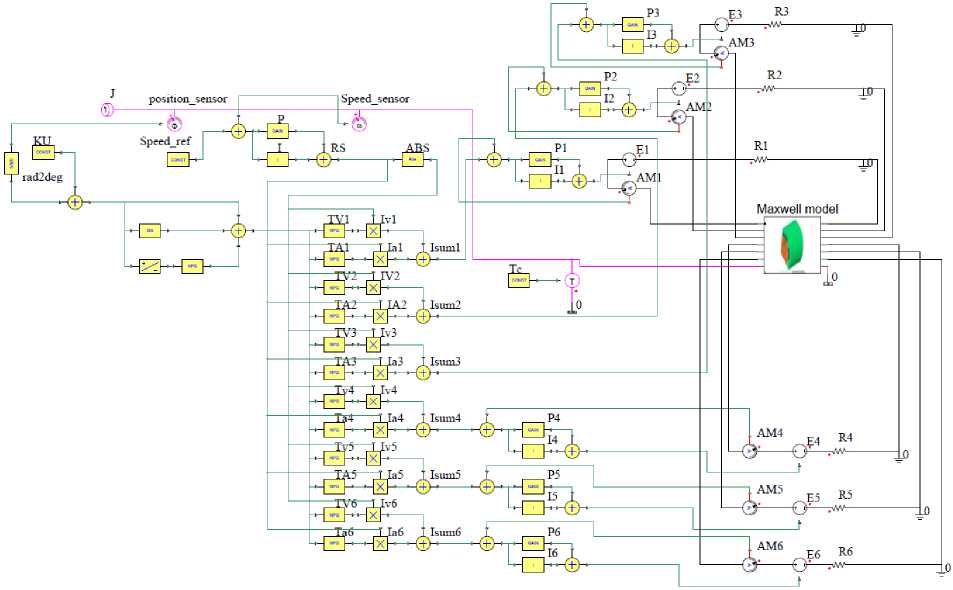
Fig. 2. Mathematical model of the electric drive with the FRRM
Torque-speed curve statistical analysis
Table
To assess the model adequacy we compared model calculation data and laboratory workbench results. The machine (rated power P = 23.5 kW, speed n = 1500 rpm, voltage V = 150 V, current I = 50 A, efficiency 0.91) and torque-current curve were taken. Table shows the statistical analysis of obtained results.
Matched samples method and Student distribution were chosen to analyze the results. Design coefficient t became less than the critical value t crit . Hence, it is possible to use the proposed model with adequate accuracy for next optimization.
Optimization of electric drive weight-size parameters
In general, the task of the weight-size parameters optimization can be described with the following criterion:
q = min NPov ( Tr, nmax, T^ ), where APOV is the electric drive power loss, Tr is the rated motor torque, n is the maximum motor max speed, and Tmax is the maximum drive torque.
The basic limitation in this task should be the heat engine power
P HE = const.
For optimizing the electric traction drive it is useful to divide speed-torque curve into 3 sections (fig. 3, a): 1 – constant power section (A-N-B curve), 2 – maximum speed section (horizontal section passing through the A point), and 3 – maximum constraint torque section (vertical section passing the B point).
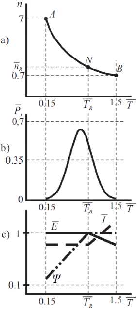
Fig. 3. Drive phase motion path (a), load distribution function (b), static characteristics (c)
In case of traction drive, e.g. electric drive of a tractor, A and B points can be limited by the technological process conditions – maximum torque is the slipping torque. If during the drive design, it is necessary to overview the location of the points, such parameters of the power equipment as drive power, gear reduction rate, must be overviewed. Typically, it occurs if high overloads or extended speed range are difficult to be realized by means of electric drive.
First section optimization on the steady-state mode
The A-N-B curve (fig. 3, a) is boundary and it is limited by the diesel generator power. There are two parts of the curve: AN – voltage V and current I are constant values, magnetic flux is varying with the torque; NB – voltage V decreases, current I rises with the following law:
P el = VI = const.
The A-N-B curve position changes with varying the gear reduction rate. In the electric traction drive with the FRRM the basic task of better motion path selection on the first section can be divided to the task of providing maximum torque and speed of the drive.
Due to criteria of minimizing the weight-size parameters of the electromechanical converter, it is worth to use maximum reduction rate gear box, but it is necessary to match rated motor speed and tool speed.
If the current and torque are linear characteristics, heating constraint can be presented as the following expression:
Tr < F J T 2 ( t ) dt ,
T 0 t 0
where Tr is the rated motor torque; T(t) is the haulertorque time curve; T0 is the overall cycle time. Load diagram for electric traction drives is usually set with frequency function Pi , which is shown in fig. 1, b and is conventional. For each concrete case this diagram would be individual. Using the NB curve and the frequency function diagram the torque RMS value can be calculated. This value is used to select the electric motor by power.
Speed regulation by changing voltage is not efficient, because the semiconductor converter power should be overrated. For this reason, it is better to use control systems with field weakening. This can reduce total power of the equipment to 40 per cent if the significant torque overloads are relatively short in time, as it is in the traction drive.
The position of N point is calculated due to criterion of the minimum electric loss. The next algorithm of switching the electric drive control structure from the first zone to the second zone can be suggested: the range that has calculations of armature winding electric loss is selected. EMFE , current I , flux Ψ as a function of torque are illustrated in fig. 3, c to clarify the estimation process. This optimization procedure can decrease weight-size parameters to 20 %.
First section optimization in transientof the electric drive
The task of finding the structure and controller parameters is essential, because when the drive works are close to the restricted area of the speed-torque curve, self-excited oscillation can occur due to the significant loop error signals [3, 5, 17, 18].
Fig. 4 illustrates the electric traction drive block diagram. This is a multi-loop control circuit. Speed control loop SCL operates with the motor speed n which is equal to linear hauler speed v 0 in relative units. Δ n sl is according to wheel slip and is taken 0.02…0.2 n . Torque control loop TCL consists of torque controller RT , path current control loops PCCL (divided into field current control loop FCCL and armature current control loop ACCL ), feedback with
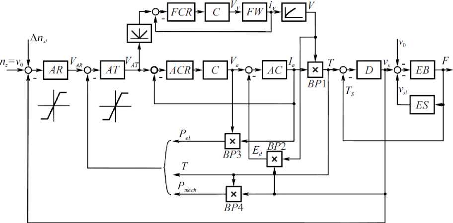
Fig. 4. Electric traction drive block diagram
b)
d)
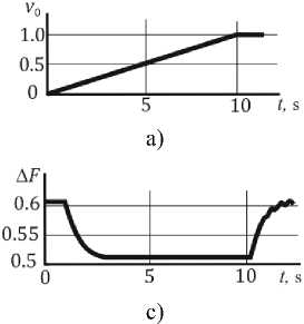
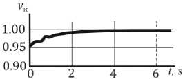
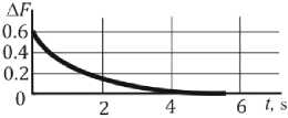
Fig. 5. Traction electric drive time diagrams: of speed (a) and traction force increment (c) during haler acceleration linearly, of speed (b) and traction force (d) when sudden traction force decrease, of speed control loop (e)
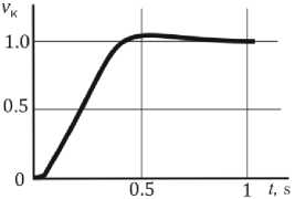
e)
electrical Pel and mechanical Pmech power, real torque T components.
Due to multi-loop control the speed-torque curve (fig. 3, a) of the traction electric drive is provided. In this respect, the limit of the drive acceptable states is composed with separate parts considering the maximum speed, heat engine power, electric drive torque, current limits. N point on the curve is corresponded to the electric traction motor rated operating mode.
The D link of the SCL realizes electric drive rotating mass inertia. Integrating elastic link EB explains the interaction between the wheel and ground. ES link in feedback registers wheelslip in motor mode and wheelskid in brake mode.
Note that the relationship between wheel traction force and slip speed is non-linear and non-stationary.
Increasing the force increases the speed in the elastic slip zone of every traction electric drive. Wheel and ground mechanical contact loss happens in the A point and the slip takes place. This mode is unallowable for the drive.
FCCL , ACCL , MCL are tuned by PI -controllers, outer SCL – by the proportional controller. System quality is defined by the transient function. Bode diagrams are also the quality evaluation.
Mathematical model of traction electric drive considers ice slick mode, when traction force decreases from maximum value to zero. Speed controller in this mode limits motor overspeed to the vehicle platform speed. Time diagrams (fig. 5) show that overshoot is limited by 5…10 % of base speed, that is highly satisfactory.
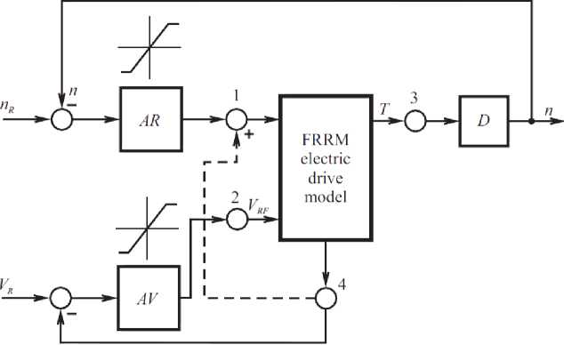
Fig. 6. Field weakening block diagram of the electric drive
Second section optimization
This stage deals with increasing electric drive speed upper limit, because the drive has to provide maximum speed higher than rated speed predetermined by the technological process. As while at rising the speed the electromagnetic torque referred to the current is falling, constant power law is not being held and the limiting speed-torque curve is distorted. If the special correction is led, the task would be solved with the dependent field weakening control system (fig. 6).
Speed controller AR holds the motor speed in the main operating zone. Voltage controller AV is used in the second zone and limits the voltage. The block “FRRM electric drive model” is described well below.
When the sign of the current changes, the phase winding lies over the interpolar space, EMF is equal to zero. That explains the decrease of ratio T / I when the speed rises. EMF signal is given to correct this difficulty.
Such improving technical measures allow extension of speed range with the electromagnetic conditions up to two times.
Third section optimization
The FRRM has very wide torque overload range. It is necessary for the traction drive when the hauler moves along the angled surface. For widening the linear zone of the electromagnetic torque curve in overloads, it is necessary to consider the proportion of active materials of the electric drive and to apply special control laws. When the copper part of the drive is increased, the linearity of the torque curve is also increased. The more efficient electric drive control system with overloads may be the series excitation control system, when armature and field currents are equal.
Conclusion
Summing up, the optimization results have shown that the electric traction drive with the field regulated reluctance machine can reach improved overload characteristics (up to 7 T / Trated in practice) and weight-size parameters (up to 50 %). Due to mentioned disadvantages of the FRRM it should be noted that torque ripples are about 20 % of rated FRRM torque and 30 % of the induction motor torque ripples. Moreover, the encoder is necessary for the operating of the drive, it certainly increases the full electric drive price. The DET-400 tractor electric drive is the commercial introduction result of the FRRM [2, 19, 20].
References Electric traction drive
- Тяговый электропривод активного прицепа трубовоза/Ю.С. Усынин, А.Н. Шишков, А.Н. Горожанкин и др.//Вестник ЮУрГУ. Серия «Энергетика». -2013. -Т. 13, № 1. -С. 137-143.
- The electric drive of a tram with an average floor/Y.S. Usinin, M.A. Grigorjev, K.M. Vinogradov et al.//SAE Technical Papers. -2008. -No. 1.
- Григорьев, М.А. Предельные возможности электроприводов с синхронной реактивной машиной независимого возбуждения и с другими типами двигателей/М.А. Григорьев//Вестник ЮУрГУ. Серия «Энергетика». -2009. -№ 34 (167). -С. 51-55.
- Параметрическая оптимизация частотно-регулируемых электроприводов/Ю.С. Усынин, М.А. Григорьев, А.Н. Шишков и др.//Вестник ЮУрГУ. Серия «Энергетика». -2012. -№ 37 (296). -С. 30-33.
- Удельные показатели электропривода с синхронным реактивным двигателем независимого воз¬буждения/Ю.С. Усынин, М.А. Григорьев, К.М. Виноградов, А.Н. Горожанкин//Вестник ЮУрГУ. Серия «Энергетика». -2008. -№ 11 (111). -С. 52-53.
- Усынин, Ю.С. Частотные характеристики канала регулирования момента в синхронных электроприводах/Ю.С. Усынин, М.А. Григорьев, А.Н. Шишков//Электричество. -2012. -№ 4. -С. 54-59.
- Пат. 2346376 Российская Федерация. Синхронная реактивная машина/Ю.С. Усынин, М.А. Григорьев, К.М. Виноградов и др. -Заявл. 12.07.2007; опубл. 10.02.2009.
- Пат. 2408972 Российская Федерация. Электропривод с синхронной реактивной машиной и способ управления им/Ю.С. Усынин, М.А. Григорьев, К.М. Виноградов и др. -Заявл. 24.12.2009; опубл. 10.01.2011.
- Пат. 2012143554 Российская Федерация. Электропривод с синхронной реактивной машиной/Ю.С. Усынин, А.Н. Горожанкин, А.Е. Бычков и др. -Заявл. 11.10.2012; опубл. 20.04.2014.
- Моделирование электропривода активного прицепа/Ю.С. Усынин, М.А. Григорьев, А.Н. Шишков и др.//Вестник ЮУрГУ. Серия «Энергетика». -2013. -Т. 13, № 2. -С. 106-113.
- Григорьев, М.А. Математическая модель синхронного реактивного электропривода с независимым управлением по каналу возбуждения/М.А. Григорьев, С.И. Кинас//Электротехника. -2014. -№ 10. -С. 60-66.
- Усынин, Ю.С. Cиловые цепи синхронных реактивных электроприводов с независимым управлением по каналу возбуждения/Ю.С. Усынин, М.А. Григорьев, Н.Ю. Сидоренко//Электротехнические системы и комплексы. -2014. -№ 2 (23). -С. 13-16.
- Математическая модель электропривода с синхронной реактивной машиной независимого возбуждения/А.М. Журавлев, Е.В. Белоусов, Д.А. Сычев, С.И. Кинас//Вестник ЮУрГУ. Серия «Энергетика». -2014.-Т. 14, № 1. -С. 66-70.
- Журавлев, А.М. Математическая модель электропривода с синхронной реактивной машиной независимого возбуждения/А.М. Журавлев, Е.В. Белоусов, Д.А. Сычев//Фундаментальные проблемы технических наук: сб. ст. Междунар. науч.-практ. конф. г. Уфа, Респ. Башкортостан, Российская Федерация/отв. ред. А.А. Сукиасян. -Уфа, 2014. -С. 58-63.
- Сычев, Д.А. Улучшение удельных показателей синхронных реактивных электроприводов/Д.А. Сычев, С.И. Кинас, А.М. Журавлев//Достижения и перспективы технических наук: сб. ст. Междунар. науч.-практ. конф. Научный центр «АЭТЕРНА», г. Уфа, Россия. -2014. -С. 38-45.
- Григорьев, М.А. Электропривод с синхронной реактивной машиной независимого возбуждения/М.А. Григорьев//Известия высших учебных заведений. Электромеханика. -2013. -№ 4. -С. 32-36.
- Усынин, Ю.С. Электроприводы и генераторы с синхронной реактивной машиной независимого возбуждения/Ю.С. Усынин, М.А. Григорьев, К.М. Виноградов//Электричество. -2007. -№ 3. -С. 21-26.
- Бычков, А.Е. Оптимизация новых типов электромеханичеcких преобразователей в электротехнических комплексах/А.Е. Бычков, Д.И. Кашаев, Т.Т. Москов//Вестник ЮУрГУ. Серия «Энергетика». -2011. -Т. 15, № 15 -С. 62-66.
- New brushless synchronous machine for vehicle application/Yu.S. Usinin, M.A. Grigorjev, K.M. Vinogradov, S.P. Gladyshev//SAE Technical Papers. -2007. -No. 1.
- Тяговый электропривод трактора ДЭТ-400/А.Н. Шишков, Д.А. Сычев, А.Е. Бычков, Н.Ю. Сидоренко//Электротехника. -2014. -№ 10. -С. 24-26.
