Energy Efficient Fitness Based Routing Protocol for Underwater Sensor Network

Author: Md. Ashrafuddin, Md. Manowarul Islam, Md. Mamun-or-Rashid
Journal: International Journal of Intelligent Systems and Applications(IJISA) @ijisa
Article in issue: 6 vol.5, 2013.
Free access
Underwater sensor network is one of the potential research arenas that opens the window of pleasing a lot of researcher in studying the field. Network layer of the underwater sensor networks must be one of the most attractive fields to build up anew protocol. In this paper, we proposed a underwater sensor network routing protocol named Energy Efficient Fitness based routing protocol for under water sensor networks (EEF) that promises the best use of total energy consumptions. The proposed routing protocol takes into account residual energy, depth and distance from the forwarding node to the sink node to guide a packet from source to the destination node. The prominent advantages of the proposed protocol are to confirm higher network life time and less end to end delay. The proposed protocol does not use control packet that causes much energy consumption and end to end delay. Simulation has been performed to certify the better result of the proposed routing protocol.
UWSNs, Fitness, Holding Time, Heuristic Function
Short address: https://sciup.org/15010433
IDR: 15010433
Text of the scientific article Energy Efficient Fitness Based Routing Protocol for Underwater Sensor Network
Published Online May 2013 in MECS
About seventy percentages of the earth is covered by water. This huge area is continuously being explored with view to discovering hidden knowledge and unknown resources. The research under water is being accomplished for the purpose of many kinds of application such as ocean sampling networks, environmental monitoring, undersea explorations, disaster prevention and mine reconnaissance [1,2,3]. Underwater sensor network(UWSNs) has been appeared as a new dimension that helps in investigating the vast area under water and provides vital information to the surface. One of the imperative sections of underwater sensor network is to mature the routing protocols that are already existed and to revamp the routing protocol for UWSNs. In order to develop the routing protocol for UWSNs, Some concerns pertaining to sensor networks have to be considered. UWSNs have to face some challenges such as node mobility, limited battery, limited bandwidth and multi path noise. In UWSNs, the node moves with the velocity of 3-6km/h[4] because of water current. So, it is not possible to progress routing protocols which works with the whole topology. Moreover, the battery of underwater sensor node cannot be recharged or changed because of harsh under water environment. Underwater sensor node uses acoustic modem which propagation speed is 1500m/s [5] to transfer data to each other. Our proposed routing protocol is devised by cogitating upon limited battery and limited bandwidth. Our proposed routing protocol provides shorter end to end delay and evades control packets to guide data packet to the destination entirely which hoards up huge amount of total energy. Information of control packet instead of using control packets to discover path is incorporated in the data packet.
The rest of this paper is organized as follows. We describe related works in Section II. Our proposed Energy Efficient Fitness based routing protocol for Underwater Sensor Network is presented in Section III and the simulation results are presented in Section IV. Finally, we conclude the paper in Section V along with future research direction.
-
II. Related Works
One of the primary topics for any network is routing and routing protocols are regard as indictment of determining and preserving the routes. Most of the research works pertaining to underwater sensor networks have been on the issues related to physical layer. On the other hand, routing techniques are comparatively new arena of network layer of UWSNs. Thus providing an efficient routing algorithm becomes a significant mission. Although underwater acoustic has been continued to study for decades, underwater networking and routing protocols are still at the infant stage of research. We have studied some routing protocol to shape our own routing protocol.
VBF (Vector Based Forwarding)[5]guides the packet from the source to the destination. Packets are forwarded only by those sensor nodes that are within a range R of the vector. The forwarding process of VBF is thought to be a routing pipe (virtual pipe) between the source and the destination node. The energy of the network is saved because only the nodes that come across the forwarding path are involved in packet routing. It provides small data delivery ratio in sparse networks. More over delivery ratio decreases when nodes are mobile and is sensitive to the routing pipe's radius. High communication time in dense network is needed and multiple nodes act as relay nodes.
To reduce the high communication time and to handle node mobility, VBF routing protocol has been modified and was proposed a HH-VBF (Hope by hop VBF)[6] routing protocol. This protocol forms the routing pipe in a hop- by-hop fashion enhancing the packet delivery ratio significantly. It does not use single virtual pipe and each node forwards packet based on its current location. When a node receives a packet, it first holds the packet for some times. Each node in the neighborhood may hear the same packet multiple times. Each node's overhearing the duplicate packet transmission to control the forwarding of this packet is allowed in HH-VBF routing protocol. In sparse networks, HH-VBF can discover a data delivery path as long as there exists one in the network. It also suffers from some disadvantages such as long propagation delay, high energy cost in dense networks, not efficient enough with node mobility.
In SBR-DLP [7], a node knows its own location and predicts the location of the destination node where the precise knowledge of the destination's location is relaxed by it. The sender determines its next hop using information received from the candidate nodes. It eliminates the problem of having multiple nodes acting as relay nodes. It does not require to rebroadcast the RTS (request to send) every time it cannot find a candidate node within its transmitting range. In SBR-DLP, node speed causes disconnections and it gives relatively low PDR in sparse networks and has relatively high energy consumption in dense networks where performs best but better packet delivery ratio when all nodes are mobile.
DUCS (Distributed Underwater Clustering Scheme)[8] is an adaptive self- organizing protocol that forms clusters. It is considered that there are always data to be sent to the sink by the underwater sensor nodes and that power control can be used to adjust its transmission power. It tries to be adapted to the intrinsic properties of underwater environments and uses a continually adjusted timing advance combined with guard time values to minimize data loss and maintain communication quality. Nodes are organized into local clusters. One node is selected as cluster-head for each cluster. All data coming from non-cluster head nodes are transmitted to their cluster-head via a single hop. Data are received by the cluster-head node and transmitted to the sink (via the relays of other clusterheads) using multi-hop routing. DUCS incorporates randomized rotation of the cluster-head among the sensors to avoid draining the battery of any one underwater sensor in the network. As the number of the nodes decrease in the network, a slight decrease occurs in the number of data messages packet delivery ratio.
In H2-DAB [9], sink node broadcasts a hello packet and the sensor node that receives the packet is assigned a HopID by incrementing the HopID existing in the hello packet of sink node. The packet receiving node broadcast the hello packet after updating the HopID of the received hello packet. In this way, sensor nodes are given a unique address from sink nodes to source node. When the packet is forwarded to the sink node, it searches for the sensor nodes with the smallest HopID. To forward packet, this protocol utilizes only hop count which is not good indicator to forward packet because UWSN is energy constrained network. It does not guarantee Network living time because same node can be chosen again and again to transfer packet. Moreover, in this protocol, inquiry request and inquiry reply packets are to be exploited at the time of the forwarding of the data packets, which is costly in terms of delay and energy.
In [10], Multipath power control transmission (MPT) which makes use of cross layer approach was proposed. The protocol joins power control with multi-path routing. The proposed scheme has three phases named multi path routing, source- initiated power-control transmission and destination node's packet combining respectively. Primarily, the source node sends out route request packet in broadcasting way, the destination node also responds with multiple reply packets in multiple paths. Consequently multiple paths from source node to destination are created. The source node chooses the optimum path based on path lengths, number of hops and optimal energy distribution is computed during path establishment. The optimal energy distribution information is included in the data packet and sensor nodes receiving the packet select its transmission power based on the optimal energy distribution. Finally, upon receiving the data packet, the destination node combines multiple erroneous copies (since some packets might be corrupted) of a packet received from multiple paths into a single copy to recover the original packet. The limitations of the proposed scheme are the redundant packets' transmissions and probabilistic approach used in the computation of optimal energy distribution.
DBR (Depth based routing)[11] is an underwater sensor network routing protocol which is based on the depth information of each sensor. In this routing protocol, No complete dimensional information of location of the sensor nodes is required and it can manage a dynamic network. In DBR, to deliver a packet, it determines the closer to the destination the smaller the depth of the forwarding nodes becomes and to receive a packet it compares depth dp retrieval of the previous hop and it's receiving node's depth for the qualified candidates to forward the packet. DBR has good energy efficiency but not so much good performance for the dense network where it has significant end to end delay and high total energy consumption.
All of these discussed routing protocols for UWSNs are efficient and effective in their own ways. In this paper, we have developed a routing protocol to overcome the disadvantages of the Depth Based Routing protocol [11]. In DBR, the forwarding node takes the decision of packet forwarding based on only depth which can make more forwarding nodes compatible to forward a packet because of node’s same depth.
We introduce a fitness function which is calculated by considering the node’s depth, residual energy, and distance from the sending node to the forwarding node and distance from the forwarding node to the sink node. We calculate holding time which is calculated in DBR based on only depth based on the above said parameters for the purpose of making each forwarding node’s waiting time different after receiving packet.
-
III. A Energy Efficient Fitness based Routing Protocol for Underwater Sensor Network
-
3.1 Network Architecture
In this section, we present our energy efficient fitness based routing protocol (EEF) in detail. Multiple-Sink underwater sensor network architecture has been applied in the proposed routing protocol. In this section, we have discussed about Network Architecture, Protocol Overview and Protocol Design. Finally we present the algorithm and flow chart of the proposed routing protocol.
It is pointed out before; the multiple-sink underwater sensor network architecture [11] can be used by the proposed routing protocol, the energy efficient fitness based routing protocol (EEF). Like DBR [11], it also takes advantages of the multiple-sink underwater sensor network architecture. An example of such networks is demonstrated in fig 1.
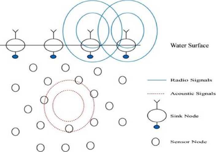
Fig. 1: Multiple-Sink underwater sensor network architecture [11]
In this multiple-sink network, the water surface nodes that are called sink nodes are equipped with the modem that is capable of capturing both radio-frequency and acoustic signal. The nodes that send and receive only acoustic signal are deployed in the underwater environment. Underwater sensor nodes with acoustic modems are placed in the interested 3-D area and each such node is assumed likely to be a data source.
Underwater acoustic nodes can accumulate data and also assist to convey data to the sinks. When a sink node receives a packet from an underwater acoustic node, the sink node can converse with each other efficiently via radio channels. The protocol attempts to send a packet to any sink nodes on the surface because if a surface node receives a packet it can send the packet other sinks or remote data centers quickly due to the speed of radio- frequency (with a propagation speed of 3 X 10⁸m/s in air) which is five orders of magnitudes higher than sound propagation (at the speed of 1.5 X 10³m/s in water) [5]. Here, the protocol does not pay attention to the communication between surface nodes. Instead it tries to transmit a packet to any surface sinks and assumes that the packet reaches to its destination. The protocol has been built by considering the fact that every node knows its depth which is the vertical distance from the node's position to the surface and its position.
-
3.2 Overview of Energy Efficient Fitness based Routing Protocol for UWSNs
-
3.3 Protocol Design
-
3.3.1 Packet Format
-
3.3.2 Reckoning Fitness
In our proposed routing protocol, we assume that we know the location of the sink node. The protocol works as the following way. First, the source node calculates the fitness of its own and incorporates the fitness value and its position in the data packet and broadcasts it. The one hop neighboring nodes which get the packet calculate their own fitness that actually define whether they forward the packet or simply discard. After receiving the packet, the forwarding node compares its fitness with the sending node’s fitness incorporated in the packet. If the fitness of the forwarding node is greater than that of the sending node, then it forwards the packet otherwise it discards the packet. In this process, more nodes may take part in forwarding packet; In order to prevent more nodes to forward the same packet, the forwarding nodes wait for a time period which is assumed based on the residual energy, depth, and distance from the sending node to the forwarding node. The holding time of the forwarding nodes vary from each other. The node which is the fittest waits less time than that of other forwarding nodes. Consequently, other forwarding nodes overhear the same packet and avoid forwarding the packet.
Protocol design takes into account of packet format used by the proposed protocol and the calculation of fitness is performed in this section. Holding time for the forwarding nodes is estimated and finally the proposed routing protocol algorithm and flow chart is presented.
The Packet used by the proposed protocol is demonstrated in Table 1. The packet header consists of the five fields: Sender ID (SID), Packet Sequence Number (PSN), Sender Fitness (SF), Sending Node’s Location(SNL), Destination Node’s Location(DNL) and Data. ”Sender ID” is the identifier of the source node. ”Packet Sequence Number” represents a unique sequence number that is assigned by the source node to the packet. Packet Sequence Number together with Sender ID is required to differentiate packets in later data forwarding.
Table 1: Data Packet Format
|
SID |
PSN |
SF |
SNL |
DNL |
Data |
The fitness illustrated in fig 2 is calculated with the help of a node residual energy, depth and distance from the node to the sink and the distance from the forwarding node to the sending node. The fitness function of the forwarding node is expressed the following ways.
f (Р-^ = y^) X h^) (1)
Here, we expressed the fitness of the forwarding node by f(n f ) which is calculated with the help of the two functions g(n^ and ft(n ^ ), a heuristic function that is calculated based on the distance between the forwarding and the sending node. We know that the more residual energy is, the more capable the node is to forward the packet, the less the depth, the more suitable the node is to be chosen as forwarding node that means more positive depth difference between the forwarding node and the sending node, the more capable the forwarding node is to broadcast the packet. The more the distance between the sending node and the forwarding node the less time the packet reaches sink node. Hence by considering such kind of properties of residual energy, depth difference and distance between the sending node and the forwarding node with packet forwarding, we can develop a relation as (2) between these parameters to take the decision of packet forwarding.
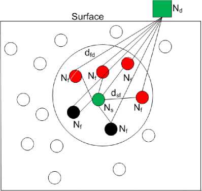
Fig. 2: Estimation of fitness
9 (df) = f x d epthdf f x dsf
Where, d Sf is the distance between the sending node and the forwarding node. E^ represents residual energy of the forwarding node and dep thd f f is the difference of vertical distance from the position of the forwarding node and the sending node to the surface. We estimate h(rif) as the inverse of the distance between the forwarding and the sink, because the less the distance between these two node, the more appropriate the node is to forward the packet.
^Н» (3)
Where d f d is the distance between the forwarding node the destination node. Now the fitness stands as follows:
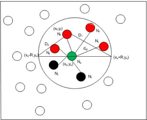
Fig. 3: Calculation of Holding Time
f Gy) =
E^ xd epthdifX* S Xf
dfd
-
3.3.3 Calculation of Holding Time
Now we can calculate the waiting time for the forwarding nodes before broadcasting the packet. The node with higher depth and less distance from the sending node to the forwarding node wait more time and the node with higher residual energy wait for less time. So, we can set a priority (P) that can be calculated as follows
P = ^ (5)
The higher fitness, the less time the forwarding node waits. The ultimate waiting time is calculated as follows:
T = К + P (6)
Where = - , D is the maximum distance that a v forwarding node within the upper half region of the sending node’s range can have. So we need to consider the time for a packet to pass the distance. Otherwise, other forwarding node does not overhear the packet as a result they forward the packet. D Illustrated in fig 3 can be calculated as follows.
Di = V[{(%s -R)-Xf }2 + {(ys - yf)}2]
d2 = V|{Gs + R) -xf}2 + {(ys - yf)}2]
D = Max (DY, D)
-
3.3.4 Routing Algorithm
The proposed routing algorithm is presented in this section. Here, f(ds) fitness of the sending node and
( ) fitness of the forwarding node and is the holding time.
Algorithm 1
Require: Data Packet
Ensure: Forwarding decision
-
1: Extract f^^ from data packet
-
2: if E ^ > Threshold Energy then
-
3: Calculate fQn^add T
-
4: if f (d f ) > f (ds ) then
-
5: Wait for T period
-
6: Broadcast packet
-
7: else
-
8: Discard the packet
-
9: end if
-
10: else
-
11: Discard the packet
-
12: end if
-
3.3.5 Flow chart of EEF
Where R is the transmission range and V is the velocity of sound. It ensures the most suitable forwarding node broadcasting the packet, other forwarding nodes overhear the packet before elapsing their waiting time and restrain them to forward the packet.
The flow chart of the proposed UWSNs routing protocol is illustrated in fig 4.
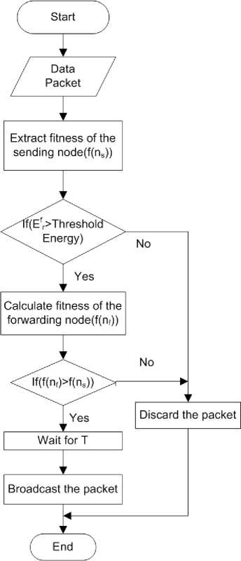
Fig. 4: Flow chart for EEF
-
IV. Performance Evaluation
-
4.1 Simulation Setting
-
4.2 Performance Metrics
In this section, we evaluate the performance of the proposed UWSN routing protocol and compare the performance of DBR[11].
All simulations are performed by using the Network Simulator (ns2)[13] with an underwater sensor network simulation package (called Aqua-Sim) extension. In our simulations, sensor nodes are deployed in a 500т× 500т ×500т3D area. The position of each node is generated randomly. Multiple sinks are randomly deployed at the water surface. Sink nodes are considered as stationary while the sensor nodes are considered to be considered to be mobile at the speed of water current. In order to measure the performance of the proposed routing protocol, different speed of water current are considered and the minimum and maximum speed of water current are taken 1т/s and 10т/S respectively. In underwater environment, the sensor nodes move in random direction, for easy simulation we have defined the direction of each sensor nodes in 3D space randomly. Each node generates two packets per second and the size of data packet is 76 byte and bit rate is 10kbs. The transmission range of the simulation is fixed 100т in all directions. The total power consumption in sending, receiving and idling mode is assumed 3w . The threshold energy of the sensor node is presumed 80 Joule. For the ease of simulation, the source node is chosen from the bottom of the taken 3D space. The same broadcast Media Access Control (MAC) protocol as in [11] is used in our simulations. In this MAC protocol, when a node has a packet to send, it first senses the channel. If the channel is free, it continues to broadcast the packet. Otherwise, it backs off. The packet will be dropped if the maximal number of back offs have been reached.
The following metrics are pointers used to appraise the performance of the proposed routing protocol.
Network Life Time : Network life time expresses the time that the energy of the first node in the network turns into to be fully exhausted.
Total Energy Consumption: Total energy consumption is computed through the total energy consumed in packet delivery including transmitting, receiving, and idling energy consumption of all nodes relaying the packet from the source node to sink node in the network.
Average End-to-End Delay: Average end-to-end corresponds to the average time needed by a packet to go from the source node to any of the sinks.
Packet Deliver Ratio: Packet delivery ratio is evaluated as the ratio of the number of distinct packet captured successfully by the destination node to the total number of packets spawned at the source node
-
4.2.1 Network Life Time
-
4.2.2 Total Energy Consumption
The network life-time of EEF and DBR [11] in random topology is illustrated in fig 5.
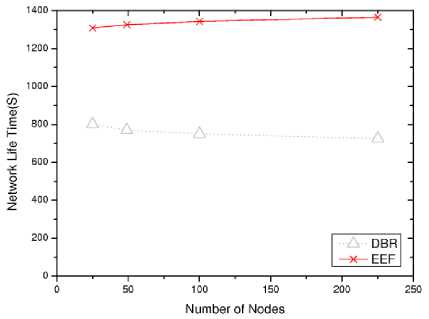
Fig. 5: Comparison of network life time
In EEF, a forwarding node is chosen based on depth, residual energy, the distance from sending node to the forwarding node and the distance from the forwarding node to the sink node. On the other hand, in DBR[11] the forwarding node is chosen based on only depth. Consequently, it has very change to die any node soon. But in the proposed protocol, after being convinced about the threshold residual energy a node calculate its fitness and forwards the packet, so it guarantees the high network life time.
The comparison of the performances of EEF and DBR[11] in terms of energy consumption with different node mobility is illustrated in fig 6. The energy consumption in DBR is higher than that of EEF. Because in DBR, more nodes involve in forwarding the same packets as it may happen that more than one node has the same depth and it causes the same holding time. But in EEF protocol, it has no change to be the same waiting time for the forwarding node as it is calculated not only based on depth but also residual energy and distance from the sending node to the forwarding node.
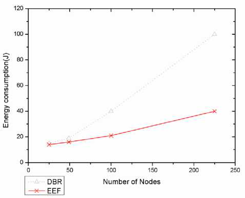
Fig. 6: Comparison of energy consumption of EEF with DBR
-
4.2.3 End to End Delay
-
4.2.4 Packet Delivery Ratio
In fig 7 end-to-end delay of EEF and DBR[11] is shown respectively. The holding time in DBR is proportional to the depth. So, forwarding node has to wait for long time. On the contrary, the holding time in EEF is calculated based on the depth, residual energy and the distance from the sending node to the forwarding node which ensure the less time for a forwarding node to wait and separate holding time for each forwarding node. The holding time in EEF certifies that the most fit forwarding node wait less time than any other forwarding node.
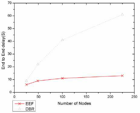
Fig. 7: Comparison of end-to-end delay between EEF and DBR
Fig 8 shows the delivery ratio as the function of the number of nodes
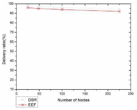
Fig. 8: packet delivery ratio between EEF and DBR
EEF routing protocol provides less delivery ratio than that of DBR protocol. Although redundant packet transmission does not take place in the proposed routing protocol but as the forwarding nodes with the high fitness always forward the packet so delivery ratio is a little bit less than that of DBR.
-
V. Conclusion
In this paper, we presented an Energy Efficient Fitness based routing protocol that is receiver based routing protocol. The forwarding node always takes decision based on some important parameters. To discover forwarding path, control packet is completely avoided in the protocol which is the most necessary for meeting the challenges of UWSNs. Network-life time has been confirmed by considering residual energy of forwarding sensor nodes. In future, we think of making better synchronization of the holding time among the forwarding nodes.
Acknowledgments
This work was supported by the Research Center of Computer Scinece and Engineering, Mawlana Bhashani Science and Technology University, Tangail, Bangladesh. The authors are grateful for this support.
References Energy Efficient Fitness Based Routing Protocol for Underwater Sensor Network
- F. Akyildiz, D. Pompili, and T. Melodia. Challenges for efficient communication in underwater acoustic sensor networks. ACM Sigbed Review, 1(2):3–8, 2004.
- J. Heidemann, Y. Li, A. Syed, J. Wills, and W. Ye. Underwater sensor networking: Research challenges and potential applications. USC/ISI Technical Report ISI-TR-2005-603, 2005.
- J.A. Rice. Undersea networked acoustic communication and navigation for autonomous mine countermeasure systems. In Proceedings of the 5th International Symposium on Technology and the Mine Problem, 2002.
- L. Guo, P.H. Santschi, M. Baskaran, and A. Zindler. Distribution of dissolved and particulate in seawater from the gulf of mexico and off cape hatteras as measured by sims. Earth and Planetary Science Letters, 133(1):117–128, 1995.
- P. Xie, J.H. Cui, and L. Lao. Vbf: vector-based forwarding protocol for underwater sensor networks. Networking 2006. Networking Technologies, Services, and Protocols; Performance of Computer and Communication Networks; Mobile and Wireless Communications Systems, pages 1216–1221, 2006.
- N. Nicolaou, A. See, P. Xie, J.H. Cui, and D. Maggiorini. Improving the robustness of location-based routing for underwater sensor networks. In OCEANS 2007-Europe, pages 1–6. IEEE, 2007.
- J. Heidemann, Y. Li, A. Syed, J. Wills, and W. Ye. Underwater sensor networking: Research challenges and potential applications. USC/ISI Technical Report ISI-TR-2005-603, 2005.
- M.C. Domingo and R. Prior. Design and analysis of a gps-free routing protocol for underwater wireless sensor networks in deep water. In Sensor Technologies and Applications, 2007. SensorComm 2007. International Conference on, pages 215–220. IEEE, 2007.
- M. Ayaz and A. Abdullah. Hop-by-hop dynamic addressing based (H2-DAB) routing protocol for underwater wireless sensor networks, In proceedings of the International Conference on Information and Multimedia Technology (ICIMT 2009), pages 436–441. Jeju Island, Korea, 2009.
- Z. Zhou and J.-H. Cui. Energy efficient multi-path communication for time-critical applications in underwater sensor networks. in 9th ACM International Symposium on Mobile Ad Hoc Networking and Computing (MobiHoc 2008), 2008:221–230, 2008.
- H. Yan, Z. Shi, and J.H. Cui. Dbr: depth-based routing for underwater sensor networks. NETWORKING 2008 Ad Hoc and Sensor Networks, Wireless Networks, Next Generation Internet, pages 72–86, 2008.
- W. K. Seach and H. X. Tan. Multipath virtual sink architecture for underwater sensor networks. OCEANS, May 2006.
- The Network Simulator NS-2. http://www.isi.edu/nsnam/ns/doc/index.html, 2002.
