Evaluation of the radiation patterns of aircraft slot antennas using iterative techniques
Автор: Bigildin I.M., Khashimov A.B.
Рубрика: Инфокоммуникационные технологии и системы
Статья в выпуске: 2 т.16, 2016 года.
Бесплатный доступ
The rigorous electromagnetic formulation of the problem to define the pattern of slot antennas mounted on aircraft is used Fredholm’s integral equation of II kind. For calculation of the slot antenna far-field pattern on perpendicular plane to aircraft axis is used an asymptotic correspondence of 3D and 2D problems in antenna engineering. We assume that slot antenna axis is parallel to aircraft axis. It is shown such correspondence is increasing the abilities of modeling the radiation pattern of slot antennas and arrays. High-precision Gauss quadrature formulas is used for matrix elements calculation. Turn from direct numerical tecniques of the integral equation solving to iterative procedures requires preliminary analysis of the using methods, especially for convergence of large-scale problems. On the base of multiple numerical experience for solving some widely-known test poblems we defined the most methods for solving such problems - conjugate gradients squared method and generalized minimum residual method. Numerical result shows that patterns of the aircraft slot antennas have a large number of directional s.
Slot antenna, aircraft, pattern, asymptotic correspondence, integral equations, iterative techniques
Короткий адрес: https://sciup.org/147155116
IDR: 147155116 | УДК: 621.396.6(07), | DOI: 10.14529/ctcr160206
Текст научной статьи Evaluation of the radiation patterns of aircraft slot antennas using iterative techniques
The slot antennas often used as radiating system of radio equipment for an aircraft. An advantage of such antennas is feasible combining and mounting on an aircraft surface. The slot antennas design should be considered the influence of an aircraft surface. It means that the slot antenna is a part of an aircraft structure and surface, typically, is metal of high specific conductivity. Thus, primary electromagnetic field radiated the slot antenna to induce on an aircraft surface the current is essentially a surface current, it is a source of the secondary scattering field. Therefore, the exciting slot antenna and an aircraft surface form a single radiating system. Total radiation field is the result of interference of the primary and secondary fields. This leads to significant distortions of the slot antenna own pattern, as scattering field defines complex shape of the aircraft surface. Furthermore, for the aircraft slot antenna it is necessary to use cavity for providing optimal pattern. Thus, to own resonant characteristics of the slot antenna add loaded cavity-resonator Q, therefore band is significantly narrowed [1]. The slot antenna location on an aircraft surface depends on the desired pattern properties. For telemetry and command control systems is desirable to use patterns, close to uniform on a plane perpendicular to the axis of an aircraft. We consider dependence the slot antenna pattern on it location on an aircraft surface, assuming the linear polarization of it.
Applying the rigorous electromagnetic equations to form mathematical model of such problem we can consider the detail dependence of mutual coupling of all part an aircraft surface and the slot antennas or the slot array. Known approximate methods of physical optics [2] can provide useful evaluations of the pattern distortion for complex shape objects, but complete form of the scattered fields may be obtained only on basis of the solution of the corresponding rigorous electromagnetic problem.
We use an asymptotic correspondence of 3D vector and 2D scalar electromagnetic problems [3]. It is possible only for extensive aircraft surface and only for defining the patterns on a plane perpendicular to the axis of an aircraft. Thus, in this case the original slot antenna is substitute the filament of the equivalence magnetic current. The limit radius of the filament is
a <
Инфокоммуникационные технологии и системы
j v ( P ) + ik J j v ( q ) H 1 ( 2 ) ( kr pq ) n r dl q = 2 H i ( p ) , (1)
-
2 L rpq
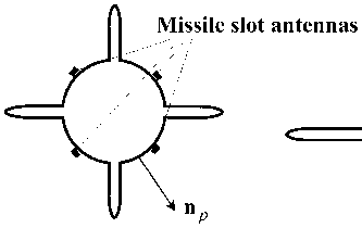
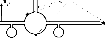
where j v is an electric current on the contour L , as cut of an aircraft surface S the plane ф = 0 (Fig. 1); H ( 2 ) ( kr pq ) is the Hankel function first order and second kind for corresponding argument; r pq is the radius-vector is linked points of view and source; Hi is tangent to contour L component of driving magnetic field, in this case source of it is the filament of the magnetic current. We assume known the given amplitude and phase distribution 1 0, у 0 . Besides, for the aircraft cavity-resonator mounted slot antennas we assume that filament of the equivalence magnetic current is located above the perfectly conducting surface. Then, the current jv can define the far-field pattern of the total radiating system, but only for given cut plane.

Рис. 1. Typical versions to the aircraft slot antennas mounting
Aircraft slot antennas

For numerical solution of the integral equation Eq. 1 is used a special case of the method of moments as the collocation method [5], leads Eq. 1 to the system of linear algebraic equations, often large-size. The noticeable feature of this system is the dominant main diagonal providing stability of numerical solution, whether direct or iterative. Calculation of the matrix elements is used the Gauss quadrature formulas, the choice of the number of nodes is based on the adaptive procedure to analyze the stability and accuracy of numerical solution, depending on the size and configuration of the contour. For most practically used solutions the choice of 8…12 nodes is sufficient to ensure the given relative accuracy of the numerical solution proportionally 10-3.
For solving the large-scale system of linear algebraic equations A • x = b it is necessary to use iterative methods. Matrix A must be square and should be large. The column vector b must have length n . For large-scale system integer n can greater then some ten thousands. We use several MATLAB iterative methods [6], but common feature of these methods is using an auxiliary handle function my_fun to represent the numerical solution of the system as x = solver ( A , b ) , where solver is using MATLAB code. For example, function my _ fun ( x ,' notransp ' ) must return column vector is equal to A • x . We consider some iterative methods to evaluate the efficiency of solving large-scale system.
-
1 . qmr (Quasi-Minimal Residual method).
-
2. bicg (BiConjugate Gradient Conjugate Gradients).
-
3 . bicgstab and bicgstabl (BiConjugate Gradients Stabilized method).
-
4. cgs (Conjugate Gradients Squared method).
-
5. gmres (Generalized Minimum Residual method).
-
6. lsqr (Least Squares method).
-
7. minres (Minimum Residual method).
-
8. pcg (Preconditioned Conjugate Gradients method).
-
9. symmlq (Symmetric LQ method).
-
10. tfqmr (Transpose-Free Quasi-Minimal Residual method).
The criterion for the efficiency of these methods is computing time to achieve the given accuracy. Comparison of the numerical results accuracy is obtained due to solve 2D test problem as finding the radiating field of the magnetic dipole on a perfectly conducting elliptic cylinder. In this case, the solution can be represent as an infinite series for Mathieu, Mathieu-Bessel, Mathieu-Hankel functions.
Бигильдин И. М., Хашимов А.Б.
Using this analytical form of solving we can obtain the useful numerical results due to special adaptive procedure for choosing the size of summed series to provide given accuracy. For numerical solution of the Eq. 1 contour L is divided into n reasonable segments. For example, we assume that n = 7120. According to the results of numerical experiences is obtained the following conclusions.
-
1. Iterative methods pcg, minres, symmlq not provide a convergent solutions for reasonable computing time.
-
2. Most preferred iterative methods to solve Eq. 1 is qmr, cgs, gmres, lsqr. These methods provide a stable convergent solution, but gmres is the fastest method.
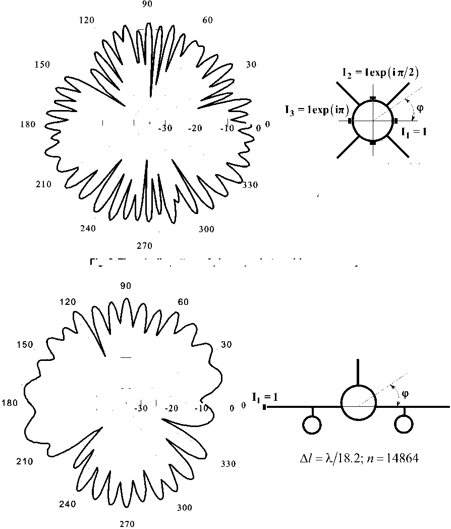
Fig. 2, 3 depict some patterns of the aircraft slot antennas and arrays on plane perpendicular to an aircraft axis (logarithmic scale in dB is used). We consider the several versions of the slot antennas location on an aircraft surface. Evidently, the patterns have a large number of directional nulls, but due to changes of an aircraft turns the interruptions of the radio channels will be short and quite acceptable.

Fig. 2. The missile pattern of phase quadrature driven slot array
I4 = 1ехр(13л/2)
А/= X/14.7; и = 7642
Fig. 3. The aircraft slot antenna pattern disposed on the edge
Инфокоммуникационные технологии и системы
Список литературы Evaluation of the radiation patterns of aircraft slot antennas using iterative techniques
- Hansen R.C. Phased Array Antennas/Hansen R.C. -J. Wiley & Sons, 2009. -560 p.
- Ufimtsev, P.Ya. Fundamentals of the Physical Theory of Diffraction. -J. Wiley & Sons, 2007. -329 p.
- Voitovich, N.I. On the Correspondence of Asymptotic Solutions to 2D and 3D Problems in Antenna Engineering/N.I. Voitovich, A.B. Khashimov//Journal of Communications Technology and Electronics. -2010. -Vol. 55, no. 12. -P. 1374-1379. Pleiades Publishing, Inc., 2010.
- Хашимов, А.Б. Применение вычислительных схем повышенной точности в проектировании антенных систем/А.Б. Хашимов, Р.Р. Салихов, Р.С. Альметов//Вестник Южно-Уральского университета. Серия «Вычислительная математика и информатика». -2014. -Т. 3, № 2. -С.77-91.
- Computer Techiques for Electromagnetics/Ed. by R. Mittra. -Pergamon Press, 1973. -488 p.
- Templates for the Solution of Linear Systems: Building Blocks for Iterative Methods/R. Barrett, M. Berry, T.F. Chan et al. -SIAM, Philadelphia, 1994. -368 p.


