Evaluation Performance of IC Engine: Linear Tunable Gain Computed Torque Controller vs. Sliding Mode Controller

Автор: Shahnaz Tayebi Haghighi, Samira Soltani, Farzin Piltan, Marzieh kamgari, Saeed Zare
Журнал: International Journal of Intelligent Systems and Applications(IJISA) @ijisa
Статья в выпуске: 6 vol.5, 2013 года.
Бесплатный доступ
Design a nonlinear controller for second order nonlinear uncertain dynamical systems (e.g., internal combustion engine) is one of the most important challenging works. This paper focuses on the comparative study between two important nonlinear controllers namely; computed torque controller (CTC) and sliding mode controller (SMC) and applied to internal combustion (IC) engine in presence of uncertainties. In order to provide high performance nonlinear methodology, sliding mode controller and computed torque controller are selected. Pure SMC and CTC can be used to control of partly known nonlinear dynamic parameters of IC engine. Pure sliding mode controller and computed torque controller have difficulty in handling unstructured model uncertainties. To solve this problem applied linear error-based tuning method to sliding mode controller and computed torque controller for adjusting the sliding surface gain (λ ) and linear inner loop gain (K). Since the sliding surface gain (λ) and linear inner loop gain (K) are adjusted by linear error-based tuning method. In this research new λ and new K are obtained by the previous λ and K multiple gains updating factor(α). The results demonstrate that the error-based linear SMC and CTC are model-based controllers which works well in certain and uncertain system. These controllers have acceptable performance in presence of uncertainty.
Internal Combustion Engine, Sliding Mode Controller, Computed Torque Controller, Linear Error-Based Sliding Mode Controller, Linear Error Based Computed Torque Controller
Короткий адрес: https://sciup.org/15010435
IDR: 15010435
Текст научной статьи Evaluation Performance of IC Engine: Linear Tunable Gain Computed Torque Controller vs. Sliding Mode Controller
Published Online May 2013 in MECS
The internal combustion (IC) engine is designed to produce power from the energy that is contained in its fuel. More specifically, its fuel contains chemical energy and together with air, this mixture is burned to output mechanical power. There are various types of fuels which can be used in IC engines namely; petroleum, diesel, bio-fuels, and hydrogen [1].
Modeling of an entire IC engine is a very important and complicated process because engines are nonlinear, multi inputs-multi outputs (MIMO) and time variant.
Controller design is the main parts in this paper as well as the major objectives in the controller design are stability and robustness. One of the significant challenges in control algorithms is design a linear controller for nonlinear systems. When system works with various parameters and hard nonlinearities this technique is very useful in order to be implemented easily but it has some limitations such as working near the system operating point[9]. Some of IC engines which work in industrial processes are controlled by linear controllers, but linear controller design for IC engines is extremely difficult [1- 6]. Computed torque controller (CTC) is a powerful nonlinear controller which it widely used in control of IC engine. It is based on feedback linearization and computes the required arm torques using the nonlinear feedback control law. This controller works very well when all dynamic and physical parameters are known but when the IC engine has variation in dynamic parameters, in this situation the controller has no acceptable performance[7-14]. In practice, most of physical systems (e.g., IC engine) parameters are unknown or time variant, therefore, online tuneable gain computed torque controller used to compensate dynamic equation of IC engine[1, 6]. Sliding mode controller (SMC) is one of the influential nonlinear controllers in certain and uncertain systems which are used to solved stability and robustness [10]. The main reason for this popularity is the attractive properties which SMCs have, such as good control performance for nonlinear systems, applicability to MIMO systems and well-established design criteria for discrete-time systems. SMC may employ unnecessarily large control signals to overcome the parametric uncertainties and difficulty in the calculation of what is known as the equivalent control [11-17]. In various dynamic parameters systems that need to be training online adaptive control methodology is used. Adaptive control methodology can be classified into two main groups, namely, traditional adaptive method and fuzzy adaptive method [18-22]. Fuzzy adaptive method is used in systems which want to training parameters by expert knowledge. Traditional adaptive method is used in systems which some dynamic parameters are known. In this research in order to solve disturbance rejection and uncertainty dynamic parameter, adaptive method are applied to sliding mode controller and computed torque controller.
There have been several engine controller designs over the past 40 years in which the goal is to improve the efficiency and exhaust emissions of the automotive engine. A key development in the evolution was the introduction of a closed loop fuel injection control algorithm by Rivard in the 1973 [2]. This strategy was followed by an innovative linear quadratic control method in 1980 by Cassidy [3] and an optimal control and Kalman filtering design by Powers [4]. Although the theoretical design of these controllers was valid, at that time it was not realistic to implement such complex designs. Therefore, the production of these designs did not exist and engine designers did adopt the methods. Due to the increased production of the microprocessor in the 1990's, it became practical to use these microprocessors in developing more complex control and estimation algorithms that could potentially be used in production automotive engines. Specific applications of A/F ratio control based on observer measurements in the intake manifold was developed by Benninger in 1991 [5]. Another approach was to base the observer on measurements of exhaust gases measured by the oxygen sensor and on the throttle position, which was researched by Onder [6]. These observer ideas used linear observer theory. Hedrick also used the measurements of the oxygen sensor to develop a nonlinear, sliding mode approach to control the A/F ratio [7]. All of the previous control strategies were applied to engines that used only port fuel injections, where fuel was injected in the intake manifold. The development of these control strategies for direct injection was not practical because the production of direct injection automobiles did not begin until the mid 1990's. Mitsubishi began to investigate combustion control technologies for direct injection engines in 1996 [8]. Furthermore, engines that used both port fuel and direct systems appeared a couple years ago, leading to the interest of developing the corresponding control strategies. Current production A/F ratio controllers use closed loop feedback and feed forward control to achieve the desired stoichio metric mixture. These controllers use measurements from the oxygen sensor to control the desired amount of fuel that should be injected over the next engine cycle and have been able to control the A/F very well.
Research on computed torque controller is significantly growing on robot manipulator application which has been reported in [1, 6, 15-16]. Vivas and Mosquera [15]have proposed a predictive functional controller and compare to computed torque controller for tracking response in uncertain environment. However both controllers have been used in feedback linearization, but predictive strategy gives better result as a performance. A computed torque control with non parametric regression models have been presented for a robot arm[16]. This controller also has been problem in uncertain dynamic models. Based on [1, 6]and [15-16] computed torque controller is a significant nonlinear controller to certain systems which it is based on feedback linearization and computes the required arm torques using the nonlinear feedback control law.
In order to solve the chattering in the systems output, boundary layer method should be applied so beginning able to recommended model in the main motivation which in this method the basic idea is replace the discontinuous method by saturation (linear) method with small neighborhood of the switching surface [1117, 38-39]. Slotine and Sastry have introduced boundary layer method instead of discontinuous method to reduce the chattering[18]. Estimated uncertainty method is used in term of uncertainty estimator to compensation of the system uncertainties. It has been used to solve the chattering phenomenon and also nonlinear equivalent dynamic. The applications of artificial intelligence, neural networks and fuzzy logic on estimated uncertainty method have been reported in [19-22]. Wu et al. [23] have proposed a simple fuzzy estimator controller beside the discontinuous and equivalent control terms to reduce the chattering. In recent years, artificial intelligence theory has been used in sliding mode control systems. Fuzzy logic controller (FLC) can be used to control nonlinear, uncertain and noisy systems. This method is free of some modelbased techniques as in classical controllers. Fuzzy logic provides a method which is able to model a controller for nonlinear plant with a set of IF-THEN rules, or it can identify the control actions and describe them by using fuzzy rules. The applications of artificial intelligence, neural networks and fuzzy logic, on nonlinear systemcontrol have reported in [24-26]. Wai et al. [24-25]have proposed a fuzzy neural network (FNN) optimal control system to learn a nonlinear function in the optimal control law. This controller is divided into three main groups: arterial intelligence controller (fuzzy neural network) which it is used to compensate the system’s nonlinearity and improves by adaptive method, robust controller to reduce the error and optimal controller which is the main part of this controller. Research on applied fuzzy logic methodology in sliding mode controller (FSMC) to reduce or eliminate the high frequency oscillation (chattering), to compensate the unknown system dynamics and also to adjust the linear sliding surface slope in pure sliding mode controller considerably improves the robot manipulator control process [27-28]. H.Temeltas [29] has proposed fuzzy adaption techniques for SMC to achieve robust tracking of nonlinear systems and solves the chattering problem. Conversely system’s performance is better than sliding mode controller; it is depended on nonlinear dynamic equation. Investigation on applied sliding mode methodology in fuzzy logic controller (SMFC) to reduce the fuzzy rules and refine the stability of close loop system in fuzzy logic controller has grown specially in recent years as the nonlinear system control [30-33]. Lhee et al. [32]have presented a fuzzy logic controller based on sliding mode controller to more formalize and boundary layer thickness.
In various dynamic parameters systems (e.g., IC engine) which need to be training, on-line tunable gain control methodology is used. In this research in order to solve disturbance rejection and uncertainty dynamic parameter, on-line tunable method is applied to artificial sliding mode controller. F Y Hsu et al. [34]have presented adaptive fuzzy sliding mode control which can update fuzzy rules to compensate nonlinear parameters and guarantee the stability robot manipulator controller.
This paper is organized as follows: In section 2, main subject of engine operating cycle and detail dynamic formulation of modelling in IC engine, sliding mode controller and computed torque controller are presented. Detail of proposed linear error-based sliding mode controller and linear error based computed torque controller are presented in section 3. In section 4, the simulation result is presented and finally in section 5, the conclusion is presented.
II. Theory2.1 Dynamic Formulation of IC Engine
Dynamic modeling of IC engine is used to describe the nonlinear behavior of IC engine, design of model based controller such as pure variable structure controller based on nonlinear dynamic equations, and for simulation. The dynamic modeling describes the relationship between fuel to air ratio to PFI and DI and also it can be used to describe the particular dynamic effects (e.g., motor pressure, angular speed, mass of air in cylinder, and the other parameters) to behavior of system[1].
The equation of an IC engine governed by the following equation [1, 4, 25, 29, 43-44]:
*PFI+ DI =
[ PTiotor 1
p
1 motor 2
[M ai
[M ]
Ṁ airn Ṁ airi2
̇̇
1 Hair2i 1 Hair22
][FṘ α̇■ ]+[ NN“
[F α ̈R̈]
N 12
N 22
+
]×[F α Ṙ̇] +
Where PF1 is port fuel injector, DI is direct injector, ̇ is a symmetric and positive define mass of air matrix, ^motor is the pressure of motor, N is engine angular speed and Ma is matrix mass of air in cylinder. Fuel ratio and exhaust angle are calculated by [25, 29, 43-44]:
{[ о tor i][ F ̇ ̇ , ]+[ ] × (2)
* : ̇ + +[ «:: ]}}
The above target equivalence ratio calculation will be combined with fuel ratio calculation that will be used for controller design purpose.
2.2 Sliding Mode Controller:
Sliding mode controller (SMC) is a powerful nonlinear controller which has been analyzed by many
researchers especially in recent years. This theory was first proposed in the early 1950 by Emelyanov and several co-workers and has been extensively developed since then with the invention of high speed control devices[11-17].
A time-varying sliding surface 5 ( X , t ) is given by the following equation:
d
s ( x , t )=(— + Л ) n 1 ̃=0 (3)
where λ is the constant and it is positive. A simple solution to get the sliding condition when the dynamic parameters have uncertainty is the switching control law:
Ur swi tch = ̂- К ( ⃗, t ). sgn (s)
и = + ur .. .
'switch
Where, the model-based component Ueq is compensated the nominal dynamics of systems. Therefore Ueq can calculate as follows:
=
[** ̇ aim N ̇ air 12+ [P notori][FṘ α̇ . ]+
[La ̇ air2i Ȧ Pmotor 2-1
[N 11 N 12] ×[FṘ ]2+[M= 1]+ (6
N 21 N22 × α̇ , +M ]+
̇]*Ṁairn Ṁ air12 +
Ṁ air2i Ṁ air22J
Where the switching function of sgn ( s ) defined as and the к ( ⃗ ⃗, t ) is the positive constant. Based on above discussion, the control law for an IC engine is written as:
Figure 1 shows pure sliding mode controller which applied to internal combustion engine.
Fig. 1: Block diagram of a variable structure controller: applied to IC engine
Computed Torque Controller: The central idea of Computed torque controller (CTC) is feedback linearization so, originally this algorithm is called feedback linearization controller. It has assumed that the desired motion trajectory for the manipulator 4d. ( t ) , as determined, by a path planner. Defines the tracking error as:
e ( t )=Qd ( t )- Qa ( t ) (7)
Where e(t) is error of the plant, Cjd ( t ) is desired input variable, that in our system is desired displacement, 4a ( t ) is actual displacement. If an alternative linear state-space equation in the form ̇ = Ax + BU can be defined as
With
=
-
• __•__
M air и
̇
11 air 12
-1
Nu
*
̇ air 21
̇
11 air 22
.([p ][Ḟ^ ċi]+
\ Lr motor 2 J
Д̇=*0 0+ x +*0+ «
[ :
Ni2
N2i
n22
]×[Fo ̇̇ ’ ] +[ ])
+
̇
̇
̇
1 1 air 12
̇
11 air 22
+
̂
and this is known as the Brunousky canonical form. By equation (7) and (8) the Brunousky canonical form can be written in terms of the state X =[ eT ̇ T ] т as [1]:
51 * ̇+ =* 0 0 0+.* ̇++* 0 + " (9)
With
|
= |
(7 = |
|
|
{(FR d + ^e + Kv)) х |
{(F/? d + Kee + Kre) х |
|
|
[Mair11 M air1Л [Ь,^1 r^ 1 *M-air,i -a .}■ ■ 1 F ‘"“ 1 + |
(10) |
* M air 11 M air 12 |}+p™°t or1 ] M air21 M |
|
W1 «121 J« VN2 1 «2 2 ]X [a;J +k2 ] |
[«11 «1 21x[F/ VN2 1 «2 2 ]X [a;J +k2 ] |
[^ <и+
Then compute the required IC engine torques using inverse of equation (10), is;
and the resulting linear error dynamics are
M airii
Mair21
M air i 2
М а^22
| (FR „ - u) +
(FR d + Kpe + Kre) = 0
[p“° r1> «J+[« motor
IS I2+6 11
^12
^22
I х
This is a nonlinear feedback control law that guarantees tracking of desired trajectory. Selecting proportional-plus-derivative (PD) feedback for U(t) results in the PD-computed torque controller [6];
According to the linear system theory, convergence of the tracking error to zero is guaranteed [6]. Where Kp and Kp are the controller gains. The result schemes is shown in Figure 2, in which two feedback loops, namely, inner loop and outer loop, which an inner loop is a compensate loop and an outer loop is a tracking error loop.
Fig. 2: Block diagram of PD-computed torque controller: applied to IC engine
The application of proportional-plus-derivative (PD) computed torque controller to control of IC engine introduced in this research.
-
III. Methodology
Linear error-based tunable gain sliding mode controller: Sliding mode controller has difficulty in handling unstructured model uncertainties. It is possible to solve this problem by combining sliding mode controller and linear error-based tuning method which this method can helps to eliminate the chattering in presence of switching function method and improves the system’s tracking performance by online tuning method. In this research the nonlinear equivalent dynamic (equivalent part) formulation problem in uncertain system is solved by using on-line linear errorbased tuning theorem. In this method linear error-based theorem is applied to sliding mode controller to adjust the sliding surface slope. Sliding mode controller has difficulty in handling unstructured model uncertainties and this controller’s performance is sensitive to sliding surface slope coefficient. It is possible to solve above challenge by combining linear error-based tuning method and sliding mode controller which this methodology can help to improve system’s tracking performance by on-line tuning (linear error-based tuning) method. Based on above discussion, compute the best value of sliding surface slope coefficient has played important role to improve system’s tracking performance especially when the system parameters are unknown or uncertain. This problem is solved by tuning the surface slope coefficient (2) of the sliding mode controller continuously in real-time. In this methodology, the system’s performance is improved with respect to the pure sliding mode controller. Figure 3 shows the linear error-based tuning sliding mode controller. Based on (5) and (6) to adjust the sliding surface slope coefficient we define f(x\X) as the linear error-based tuning methodology.
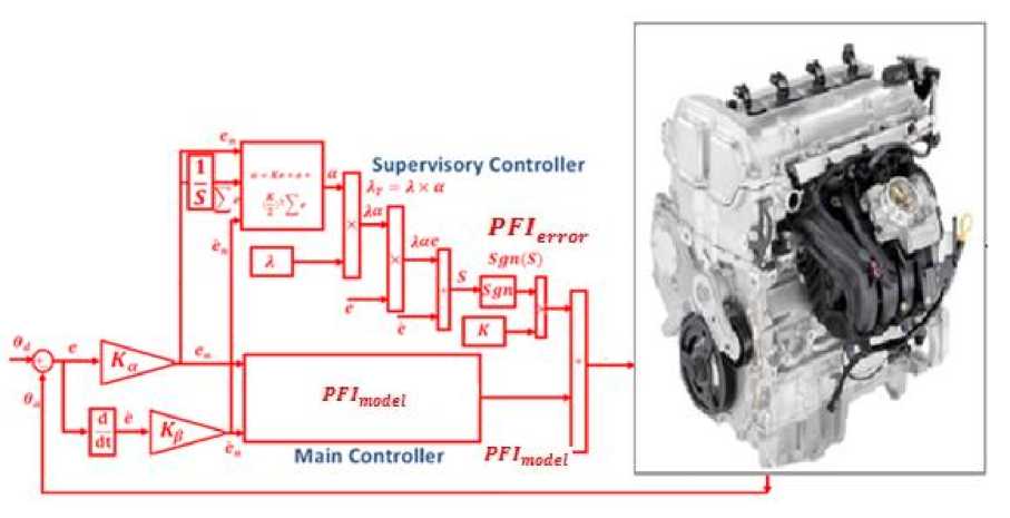
Fig. 3: Block diagram of a linear error-based sliding mode controller: applied to IC engine
/ (xl2) = 2 T a
If minimum error ( 2* ) is defined by;
2 * = arg m in [(Sup|fGd2)-/(x))] (15)
Where 2T is adjusted by an adaption law and this law is designed to minimize the error’s parameters of 2 — 2*. adaption law in linear error-based tuning sliding mode controller is used to adjust the sliding surface slope coefficient. Linear error-based tuning part is a supervisory controller based on the following formulation methodology. This controller has three inputs namely; error (e ), change of error ( e ) and the integral of error ( E e ) and an output namely; gain updating factor (a) . As a summary design a linear errorbased tuning is based on the following formulation:
a = K. e + e + ^-E e
^ on-line a.2e + e ^ ^on-line (K . e + 00
e + ^)- E e)2e + e
2 Tune
2. a ^ 2 Tune
= 2(K. e +e +
(K)2V
~Ze)
Where (a) is gain updating factor, ( E e ) is the integral of error, ( e ) is change of error, ( e) is error and K is a coefficient.
Linear error-based tuning computed torque controller: Computed torque controller has difficulty in handling unstructured model uncertainties. It is possible to solve this problem by combining computed torque controller and linear error-based tuning method which this method can helps to eliminate the error and improves the system’s tracking performance by online tuning method. In this research the nonlinear equivalent dynamic (equivalent part) formulation problem in uncertain system is solved by using on-line linear errorbased tuning theorem. In this method linear error-based theorem is applied to computed torque controller to adjust the linear inner loop gain. Computed torque controller has difficulty in handling unstructured model uncertainties and this controller’s performance is sensitive to linear inner loop gain. It is possible to solve above challenge by combining linear error-based tuning method and computed torque controller which this methodology can help to improve system’s tracking performance by on-line tuning (linear error-based tuning) method. Based on above discussion, compute the best value of linear inner loop gain has played important role to improve system’s tracking performance especially when the system parameters are unknown or uncertain. This problem is solved by tuning the linear inner loop gain (K) of the computed torque controller continuously in real-time. In this methodology, the system’s performance is improved with respect to the pure computed torque controller.
У(х|2) = 2 T a (17)
If minimum error ( 2* ) is defined by;
2* = arg min [(Sup^GW-Дх))] (18)
Where 2 T is adjusted by an adaption law and this law is designed to minimize the error’s parameters of 2 — 2*. adaption law in linear error-based tuning computed torque controller is used to adjust the linear inner loop gain. Linear error-based tuning part is a supervisory controller based on the following formulation methodology. This controller has three inputs namely; error ( e), change of error ( e ) and the integral of error ( E e ) and an output namely; gain updating factor (a) . As a summary design a linear errorbased tuning is based on the following formulation:
a = K.e + e + (^-"L e
K_(on - Zine) = a. Xe + e □ (^ ^ ) K_(on - Zine) = (K.e + e ’ + (К) л 2/2 X ■ e) Xe + e'
^Tune = ^.a^ ^Tune = ^(K. e + e + -^-^ e)
Where (a) is gain updating factor, ( Ze ) is the integral of error, ( e ) is change of error, (e ) is error and K is a coefficient.
-
IV. Results and Discussion
To validate of this work; on-line tuning sliding mode controller and on-line tuning computed torque controller are compared to control and improve the response of IC engine. The simulation was implemented in MATLAB/SIMULINK environment. Fuel ratio response, controller robustness, steady state error and RMS error are compared in these controllers. It is noted that, these systems are tested by band limited white noise with a predefined 10%, 20% and 40% of relative to the input signal amplitude. This type of noise is used to external disturbance in continuous and hybrid systems.
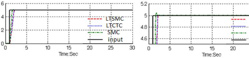
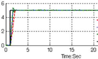
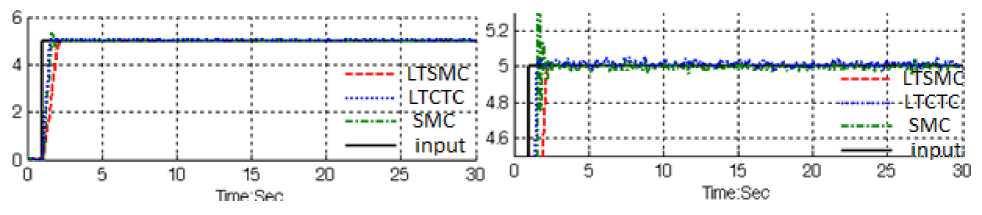
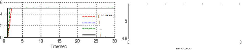
Fuel ratio response: Figure 4 is shown the fuel ratio in linear tuning SMC, SMC and linear tuning CTC in certain environment and without disturbance for desired.
Ll-SMC • LTCTC-—j sMc input-J 25 30
Fig. 4: LTSMC Vs. LTCTC: fuel ratio response
By comparing this response, Figure 4, in LTSMC and LTCTC, both of methodologies have identical response. Based on Figure 5 it is observed that, the overshoot in LTSMC is 0%, in PD-SMC’s is 1% and in LTCTC’s is 0%, and rise time in LTSMC’s is 0.6 seconds, in PD-SMC’s is 0.483 second and in LTCTC’s is about 0.6 seconds. From the trajectory MATLAB simulation for LTSMC, PD-SMC and LTCTC in certain system, it was seen that all of three controllers have acceptable performance.
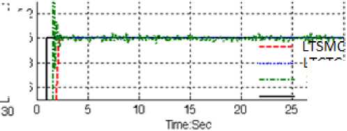
Controller robustness: Figures 5 to 7 show the power disturbance elimination in LTSMC, PD-SMC and LTCTC with disturbance. The disturbance rejection is used to test the robustness comparisons of these three controllers. A band limited white noise with predefined of 10%, 20% and 40% the power of input signal value is applied to the step trajectory. It found fairly fluctuations in trajectory responses.
|
M |
|
|
TT5MC |
5 |
|
Ltctc |
48 |
|
■SMC"- |
|
|
: input |
46 |
LTGTG: smc :
-input;
Fig. 5: Desired input, LTSMC, LTCTC and PD-SMC for IC engine trajectory with 10%external disturbance
■ttsmc; :LTGTG • :'5MC": ; input :
30 о
10 15 20
Time:Sec
Titi#* S#*n
Fig. 6: Desired input, LTSMC, LTCTC and PD-SMC for IC engine trajectory with 20%external disturbance
|
....L......._J_________L .^WNW4I|.-LTGTG' |
|
|
>1 • |
: ------L smc • |
Based on Figure 5; by comparing response trajectory with 10% disturbance of relative to the input signal amplitude in LTSMC, LTCTC and PD-SMC, LTSMC’s overshoot about (0%) is lower than LTCTC’s (0.5%) and PD-SMC’s ( 1% ) . PD-SMC’s rise time (0.5 seconds) is lower than LTCTC’s (0.63 second) and LTSMC’s (0.65 second).
Based on Figure 6; by comparing response trajectory with 20% disturbance of relative to the input signal amplitude in LTSMC, LTCTC and PD-SMC, LTSMC’s overshoot about (0%) is lower than LTCTC’s (1.8%) and PD-SMC’s (2.1%). PD-SMC’s rise time (0.5 seconds) is lower than LTCTC’s (0.63 second) and LTSMC’s (0.66 second). Based on Figure 6, it was seen that, LTSMC’s and LTCTC performance are better than PD-SMC because LTSMC and LTCTC can auto-tune the sliding surface slope coefficient and gain as the dynamic IC engine parameter’s change and in presence of external disturbance whereas PD-SMC cannot.
LTSMC LTCTC
-: SMC' input;
Fig. 7: Desired input, LTSMC, LTCTC and PD-SMC for IC engine trajectory with 40%external disturbance
|
— ””_T |
LTS^jC ; |
||
|
if П |
ттегс*" smc : input ; |
||
|
0 5 10 15 2 Tmesec |
0 25 30 |
||
Based on Figure 7; by comparing response trajectory with 40% disturbance of relative to the input signal amplitude in LTSMC, PD-SMC and LTCTC, LTSMC’s overshoot about (0%) is lower than LTCTC’s (6%) and PD-SMC’s ( 8% ) . PD-SMC’s rise time (0.5 seconds) is lower than LTCTC’s (0.7 second) and LTSMC’s (0.8 second). Based on Figure 8, LTCTC and PD-SMC have moderately oscillation in trajectory response with regard to 40% of the input signal amplitude disturbance but LTSMC has stability in trajectory responses in presence of uncertainty and external disturbance.
Steady state error: Figure 8 is shown the error performance in LTSMC, PD- SMC and LTCTC for IC engine . The error performance is used to test the disturbance effect comparisons of these controllers. In this system this time is transient time and this part of error introduced as a transient error. Besides the Steady State and RMS error in LTSMC, LTCTC and PD-SMC it is observed that, error performances in LTSMC (Steady State error =0.9e-12 and RMS error=1.1e-12) are about lower than LTCTC (Steady State error =0.7e-8 and RMS error=1e-7) and PD-SMC’s (Steady State error=1e-8 and RMS error=1.2e-6) .
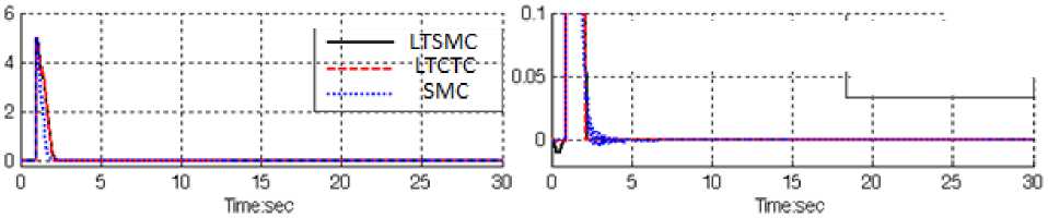
Fig. 8: LTSMC, PD-SMC and LTCTC for steady state error without disturbance
|
-■---- LTSMC _i_ tTCTC |
|
-wi—u.i. OML |
The LTSMC gives significant steady state error performance when compared to LTCTC and PD-SMC. When applied 40% disturbances in LTSMC the RMS error increased approximately 0.0164% (percent of increase the LTSMC RMS
(40% disturbance RMS error 1.8e-12 x error= = =0.0164%), no distur banc eRMS error 1.le-12
In LTCTC the RMS error increased approximately 6.9% (percent of increase the LTCTC RMS
(40% disturbance RMS error 0.69e —4 , error= = =6.9%)
no distur banc eRMS error le-7
In PD-SMC the RMS error increased approximately 9.17% (percent of increase the PD-SMC RMS
( 40 % disturbance RMS error lle-4 „ ^—n/x error= = =9.17%).
no disturbance RMS error 1.2e-6
In this part LTSMC, PD-SMC and LTCTC have been comparatively evaluation through MATLAB simulation, for IC engine control.
-
V. Conclusion
Refer to the research, a linear tuning sliding mode controller and linear tuning computed torque controller are design and compared with each other and applied to IC engine in presence of structure and unstructured uncertainties. Regarding to the positive points in classical sliding mode controller and computed torque controller in linear tuning on-line methodology, the response is improved. Linear tuning methodology by adding to the sliding mode controller and computed torque controller has covered negative points. This implementation considerably reduces the chattering phenomenon and error in the presence of uncertainties. As a result, this controller will be able to control a wide range of IC engine with a high sampling rates because its easy to implement versus high speed markets.
Acknowledgment
The authors would like to thank the anonymous reviewers for their careful reading of this paper and for their helpful comments. This work was supported by the SSP Research and Development Corporation Program of Iran under grant no. 2012-Persian Gulf-2B.
Список литературы Evaluation Performance of IC Engine: Linear Tunable Gain Computed Torque Controller vs. Sliding Mode Controller
- Heywood, J., “Internal Combustion Engine Fundamentals”, McGraw-Hill, New York, 1988.
- J. G. Rivard, "Closed-loop Electronic Fuel Injection Control of the IC Engine," in Society of Automotive Engineers, 1973.
- J. F. Cassidy, et al, "On the Design of Electronic Automotive Engine Controls using linear Quadratic Control Theory," IEEE Trans on Control Systems, vol. AC-25, October 1980.
- W. E. Powers, "Applications of Optimal Control and Kalman Filtering to Automotive Systems," International Journal of Vehicle Design, vol. Applications of Control Theory in the Automotive Industry, 1983.
- N. F. Benninger, et al, "Requirements and Perfomance of Engine Management Systems under Transient Conditions," in Society of Automotive Engineers, 1991.
- C. H. Onder, et al, "Model-Based Multivariable Speed and Air-to-Fuel Ratio Control of an SI Engine," in Society of Automotive Engineers, 1993.
- S. B. Cho, et al, "An Observer-based Controller Design Method for Automotive Fuel-Injection Systems," in American Controls Conference, 1993, pp. 2567-2571.
- T. Kume, et al, "Combustion Technologies for Direct Injection SI Engine," in Society of Automotive Engineers, 1996.
- Frank L.Lewis. Nonlinear dynamics and control, Handbook, pages 51-70. CRC press, 1999.
- Okyak Kaynak, “Guest Editorial Special Section on Computationally Intelligent Methodologies and Sliding-Mode Control”, IEEE TRANSACTIONS ON INDUSTRIAL ELECTRONICS, VOL. 48, NO. 1, 2001
- F. Piltan, et al., "Artificial Control of Nonlinear Second Order Systems Based on AFGSMC," Australian Journal of Basic and Applied Sciences, 5(6), pp. 509-522, 2011.
- Piltan, F., et al., 2011. Design sliding mode controller for robot manipulator with artificial tunable gain. Canaidian Journal of pure and applied science, 5 (2): 1573-1579.
- Piltan, F., et al., 2011. Design Artificial Nonlinear Robust Controller Based on CTLC and FSMC with Tunable Gain, International Journal of Robotic and Automation, 2 (3): 205-220.
- Piltan, F., et al., 2011. Design Mathematical Tunable Gain PID-Like Sliding Mode Fuzzy Controller with Minimum Rule Base, International Journal of Robotic and Automation, 2 (3): 146-156.
- Piltan, F., et al., 2011. Design of FPGA based sliding mode controller for robot manipulator, International Journal of Robotic and Automation, 2 (3): 183-204.
- Piltan, F., et al., 2011. A Model Free Robust Sliding Surface Slope Adjustment in Sliding Mode Control for Robot Manipulator, World Applied Science Journal, 12 (12): 2330-2336.
- Piltan, F., et al., 2011. Design Adaptive Fuzzy Robust Controllers for Robot Manipulator, World Applied Science Journal, 12 (12): 2317-2329.
- Slotine, J.J. and S. Sastry, 1983. Tracking control of non-linear systems using sliding surfaces, with application to robot manipulators. International Journal of Control, 38: 465-492.
- M. Ertugrul and O. Kaynak, "Neuro sliding mode control of robotic manipulators," Mechatronics, vol. 10, pp. 239-263, 2000.
- P. Kachroo and M. Tomizuka, "Chattering reduction and error convergence in the sliding-mode control of a class of nonlinear systems," Automatic Control, IEEE Transactions on, vol. 41, pp. 1063-1068, 2002.
- H. Elmali and N. Olgac, "Implementation of sliding mode control with perturbation estimation (SMCPE)," Control Systems Technology, IEEE Transactions on, vol. 4, pp. 79-85, 2002.
- J. Moura and N. Olgac, "A comparative study on simulations vs. experiments of SMCPE," 2002, pp. 996-1000.
- B. Wu, et al., "An integral variable structure controller with fuzzy tuning design for electro-hydraulic driving Stewart platform," 2006, pp. 5-945.
- R. J. Wai, et al., "Implementation of artificial intelligent control in single-link flexible robot arm," 2003, pp. 1270-1275.
- R. J. Wai and M. C. Lee, "Intelligent optimal control of single-link flexible robot arm," Industrial Electronics, IEEE Transactions on, vol. 51, pp. 201-220, 2004.
- M. B. Menhaj and M. Rouhani, "A novel neuro-based model reference adaptive control for a two link robot arm," 2002, pp. 47-52.
- Y. C. Hsu and H. A. Malki, "Fuzzy variable structure control for MIMO systems," 2002, pp. 280-285.
- Y. C. Hsueh, et al., "Self-tuning sliding mode controller design for a class of nonlinear control systems," 2009, pp. 2337-2342.
- H. Temeltas, "A fuzzy adaptation technique for sliding mode controllers," 2002, pp. 110-115.
- R. Palm, "Sliding mode fuzzy control," 2002, pp. 519-526.
- C. G. Lhee, et al., "Sliding mode-like fuzzy logic control with self-tuning the dead zone parameters," Fuzzy Systems, IEEE Transactions on, vol. 9, pp. 343-348, 2002.
- Lhee. C. G., J. S. Park, H. S. Ahn, and D. H. Kim, "Sliding-Like Fuzzy Logic Control with Self-tuning the Dead Zone Parameters," IEEE International fuzzy systems conference proceeding, 1999,pp.544-549.
- X. Zhang, et al., "Adaptive sliding mode-like fuzzy logic control for high order nonlinear systems," pp. 788-792.
- F. Y. Hsu and L. C. Fu, "Nonlinear control of robot manipulators using adaptive fuzzy sliding mode control," 2002, pp. 156-161.
- Lee, B., “Methodology for the Static and Dynamic Model Based Engine Calibration and Optimization” Ph.D. Dissertation, The Ohio State University, 2005.
- Dawson, J., “An experimental and Computational Study of Internal Combustion Engine Modeling for Controls Oriented Research” Ph.D. Dissertation, The Ohio State University, 2005.
- J. G. Rivard, "Closed-loop Electronic Fuel Injection Control of the IC Engine," in Society of Automotive Engineers, 1973.
- Piltan, F., et al., “Design Model-free Fuzzy Sliding Mode Control: Applied to Internal Combustion Engine,” International Journal of Engineering, 5 (4): 302-312, 2011.
- Piltan, F., et al., “Control of IC Engine: Design a Novel MIMO Fuzzy Backstepping Adaptive Based Fuzzy Estimator Variable Structure Control,” International Journal of Robotics and Automation, 2 (5), 2011.
