Experimental investigations of a plasma thrusters and its power processing units performances like an electric load of a spacecraft’s power condition system

Author: Ermoshkin Yu. M., Kochev Yu. V., Nikihelov A. V., Pervukhin A. V., Simanov R. S.
Journal: Siberian Aerospace Journal @vestnik-sibsau-en
Section: Aviation and spacecraft engineering
Article in issue: 1 vol.22, 2021.
Free access
Electro-jet (plasma or ion) thrusters are becoming increasingly common to correct a satellite orbit and perform orbit raising maneuvers to achieve the geostationary orbit. This is due to the greater efficiency of plasma thrusters compared to chemical ones. When developing a satellite platform, an important place is the matching up of the electrical character-istics of the electric power subsystem (EPS) and on-board consumers. Intrinsically, this issue is an intersys-tem problem. The lack of proper attention paid to find the timely and correct solution of this problem can complicate the operation of the satellite electric power subsystem. The most important subsystem, which has a significant impact on the operation of the satellite EPS, is the electric-jet propulsion subsystem, since among on-board consumers, this one is the most powerful consumer being switched simultaneously. Tran-sients occurred in the power supply circuits following thruster firing and shut down processes can reach significant values. An electric jet thruster only runs in conjunction with a complex electronic unit – a power processing unit (PPU), which converts the voltage of the on-board power supply into a set of voltages nec-essary for thruster components to run. Therefore, in the preliminary design of the propulsion subsystem, it is necessary to know the electrical characteristics of transients and ripples in the power supply circuits of the thruster / PPU combination being an electrical load of the Electric power subsystem. It is difficult to obtain the characteristics of such processes by the calculation method. Therefore, an experimental method is the most common and objective method to obtain this information. JSC ISS carried out tests allowing to measure characteristics of transients and ripples under firing, running and shut down of plasma thrusters of different types powered by corresponding PPU’s. These tests were conducted using a vacuum chamber GVU-60. A test power supply was used to simulate EPS operation. This paper presents the results of meas-urements and analysis of parameters of transients and ripples on PPU power buses used for thrusters and devices of three types. These results are considered to be preliminary. It is shown that the greatest difficul-ties can arise when operating high-power thrusters. It is concluded that for each new type of thrusters and PPU’s it is advisable to conduct interface tests of the propulsion subsystem and the satellite electric power subsystem.
Plasma thruster, propulsion subsystem, power processing unit, transient processes, current, voltage, rippling
Short address: https://sciup.org/148321793
IDR: 148321793 | UDC: 629.783.525 | DOI: 10.31772/2712-8970-2021-22-1-137-150
Text of the scientific article Experimental investigations of a plasma thrusters and its power processing units performances like an electric load of a spacecraft’s power condition system
Introduction. At present, electric propulsion (plasma or ion) thrusters for spacecraft orbit correction and its geostationary orbit before launching it are becoming more widespread in practical cosmonautics. This is due to the greater efficiency of plasma thrusters compared to engines powered by chemical fuel. Various versions of propulsion subsystems based on propulsion thrusters are being developed [1–5].
When developing a platform for a spacecraft (SC), coordination of electrical characteristics of the electric power supply system (EPS) and onboard consumers with significant power is important [6]. Lack of due attention to timely and correct solution of this intersystem problem can create problems for ensuring the normal operation of the SEP and, as a consequence, the spacecraft as a whole. The most significant influence on the operation of the SCS is made by the electric propulsion subsystem, since among all other consumers it is the most powerful one-time switched load.
An electric propulsion thruster works only in conjunction with a complex electronic device - a Power processing unit (PPU), which converts the onboard power supply voltage into a set of voltages required for the operation of the engine elements [7–9]. In stationary operation of the thruster and during transient processes, there are consumption current ripples caused by the peculiarities of working process, both in the plasma discharge of thruster and in the PPU [10]. This issue is of particular relevance in connection with the introduction into operation of powerful thrusters intended for additional launching of satellites from a geo-transfer orbit to a geostationary one [11], since with an increase in consumption power, influence of propulsion subsystem on the power parameters of onboard Power System (PS) increases.
Therefore, in the preliminary design of thruster subsystem, it is necessary to know the electrical characteristics of transient processes and ripplings in the power supply circuits of the thruster - PPU bundle as an electrical load of the EPS. However, the characteristics of an engine subsystem as an electrical load have not yet been investigated enough. It is difficult to obtain the characteristics of such processes by a calculation method. Theoretical studies are hampered by the lack of models that adequately describe the behavior of the thruster - PPU combination. Therefore, the most common and objective method for obtaining information about the real properties of thruster system is experimental [12; 13]. Taking into account the significance and relevance of the indicated problem, JSC "ISS" carried out tests that made it possible to measure the characteristics of transient processes and pulsations during starting, operation and shutdown of plasma engines of several types, powered by the corresponding PPU. The work was carried out vacuum test bench of GVU-60. This article provides the results of measurements and preliminary analysis of the parameters of transient processes, obtained during firing tests of thrusters of different power, used for the tasks of correcting the orbit and additional launching of spacecraft.
Research object. As an object of research in this work, the electrical characteristics of the thruster - PPU unit are taken. Thrusters and devices of three types different in power and operating parameters are considered. The power consumption of the cluster for engines that participated in the tests is given in Table 1.
Table 1
Power consumption of engine- PCS combinations for which electrical characteristics were studied
|
Type of thruster |
Total system power consumption (engine and PCS), W |
|
1 |
1065 |
|
2 |
1495 |
|
3 |
5050 |
Test equipment. Studies of transient processes and ripplings during operation of plasma thrusters were carried out at ISS JSC on the GVU-60 test bench, the basis of which was a vacuum chamber with a volume of about 80 m3. The characteristics of the test bench are presented in more detail in [14; 15]. The general view of the test bench is shown in Fig. 1. The measurements were carried out in the course of certification and acceptance tests of the propulsion subsystems for the spacecraft orbit correction. When the thrusters were operating in the vacuum chamber, an oil-free vacuum was maintained at a level of about 10–4 mm Mercury. A technological source was used as a power source imitating the PS. Simultaneously with the measurement of transient processes and ripplings, the main operating parameters of the propulsion subsystem were recorded, such as pressure at the exit from the xenon supply unit, drive, discharge current and voltage, and cathode heating current.
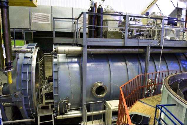
Рис. 1. Испытательный стенд ГВУ-60.
-
Fig. 1. GVU-60 test bench
Recording equipment. A TPS2024 oscilloscope, Rohde-Schwarz FSP3 and Hewlett Packard spectrum analyzers, and a current converter with spaceprobes were used as recording equipment for studying the electrical characteristics of the engine - PPU combination during tests at ISS.
The characteristics of this equipment are given in Table 2.
Table 2
Measuring equipment used in testing.
|
Name |
Designation and type |
Measurement limits, accuracy class |
|
Oscilloscope |
TektronixTPS2024 |
Measurement range from 0 to 200 MHz, Discrepancy ±4 % |
|
Spectrum analyzer |
Rohde-Schwarz FSP3 |
Measurement range 20 Hz - 3 GHz, Discrepancy 0,5 дБ |
|
Spectrum analyzer |
Hewlett Packard |
Measurement range 20 Hz - 40.1 MHz, Discrepancy 1,5 дБ |
|
HF current transducer with probes |
ТСРА300, ТСР305, ТСР303, ТСР312 |
Measurement range 0-100 MHz, Discrepancy ±3 % |
Technological power supplies, measurement scheme. A GEN 100-33-1P230 power source with a maximum output current of 33 A was used as a power supply device during fire tests of type 1 and type 2 thrusters at ISS JSC. A GEN-125-120-MD-3p400 power supply with a maximum output current of 120 A was used to power the type 3 thruster.
The scheme for measuring transient processes and pulsations is shown in Fig. 2. As a measuring device, current probes were used, which were installed in electrical circuits between the power source and PPU. To power the PPU, technological cables up to 15 m long were used, made according to the standard technology for manufacturing of on-board cables.
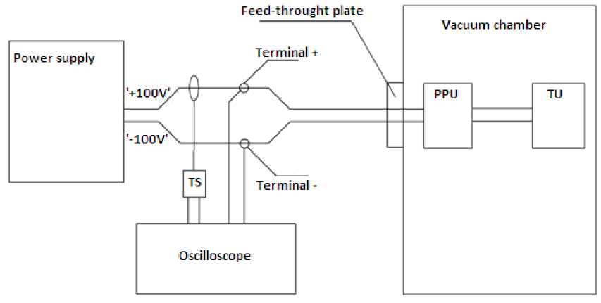
Рис. 2. Схема измерений переходных процессов двигательной подсистемы при огневых испытаниях: ТС – преобразователь силы тока ВЧ измерительный с зондами; СПУ – система преобразования и управления; БК – блок коррекции
-
Fig. 2. Scheme of the transient processes measurements at the firing tests: TS – High frequency measurement transducer of a current intensity with probes; PPU – Power processing unit; TU – Thruster Unit to orbit correction
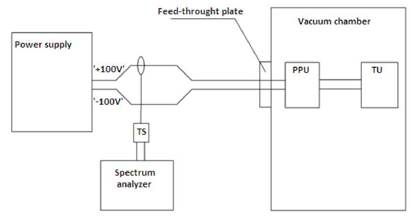
Рис. 3. Схема измерений пульсаций тока двигательной подсистемы при огневых испытаниях
-
Fig. 3. Scheme of the current rippling measurements at the propulsion subsystem firing tests
Test procedure. The tests were carried out according to the method providing for starting and stopping the thrusters according to the standard cyclogram. The thruster was started, as a rule, by starting the anode power source (discharge circuit) with a heated cathode, thermal choke, open thruster valves and an applied ignition voltage. In this sequence, the thruster was started during the growth of discharge voltage when the power source was started, that is, even before the nominal voltage was reached. Duration of the thruster operation was varied in the range from 3 minutes to 3 hours. In the sessions selected for measurements, current and voltage were oscillographic when the engine was turned on and off, that is, the characteristics of transient processes, and the parameters (peak-to-peak and frequency) of the ripples were recorded, both in transient processes and in stationary operation.
Measurement results. The results of measurements of currents and voltages at the input of the PPU (at the output from the technological power source) during starting and stopping of thrusters and PPU of three types are presented below in Fig. 4–25. To identify the characteristic features of the processes and the possibility of comparing similar parameters for thrusters of various types, the parameters are presented in relative units, in fractions of their nominal values.
Transient Processes
Starting and stopping the thruster, type 1
О 5 10 15 20 Т, ms
Рис. 4. Запуск, тип 1, переходный процесс по току
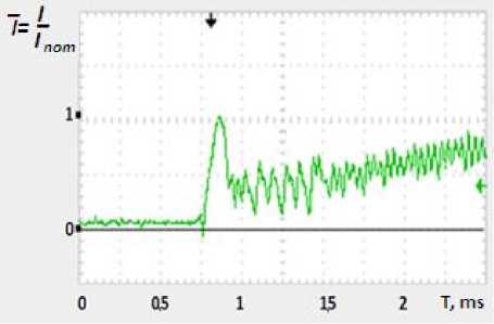
Рис. 5. Запуск, тип 1, переходный процесс по току
Fig. 4. Starting, type 1, current transient process
Fig. 5. Starting, type 1, current transient process
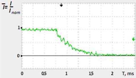
Рис. 6. Отключение, тип 1, переходной процесс по току
Fig. 6. Stopping, type 1, current transient process
Starting and stopping the thruster, type 2
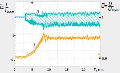
Рис. 7. Запуск, тип 2. Переходные процессы по току и напряжению
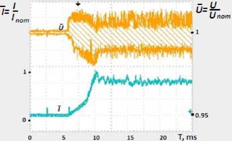
Рис. 8. Запуск, тип 2. Переходные процессы по току и напряжению
-
Fig. 7. Starting, type 2. Current and voltage transient process
-
Fig. 8. Starting, type 2. Current and voltage transient process
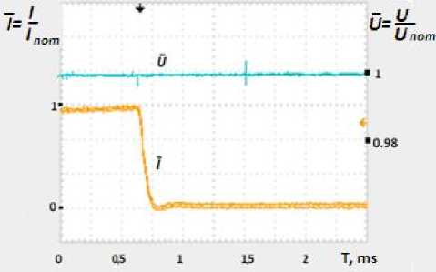
Рис. 9. Отключение, тип 2. Переходные процессы по току и напряжению
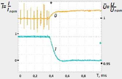
Рис. 10. Отключение, тип 2. Переходные процессы по току и напряжению
Fig. 9. Stopping, type 2. Current and voltage transient process
Fig. 10. Stopping, type 2. Current and voltage transient process
Starting and stopping the thruster, type 3
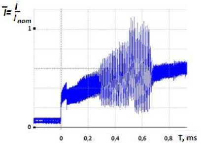
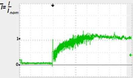
Рис. 11. Двигатель, тип 3. Ток потребления Рис. 12. Двигатель, тип 3. Ток потребления при запуске при запуске и в стационарной работе
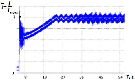
Fig. 11. Thruster, type 3. Current consumption Fig. 12. Thruster, type 3. Current consumption at starting at starting and stationary operation
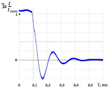
Рис. 13. Двигатель, тип 3. Ток потребления при отключении
Fig. 13. Thruster, type 3. Current consumption at stopping
Ripple
Ripples, thruster type 1
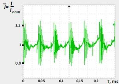
Рис. 14. Стационарная работа двигателя, тип 1. Пульсации тока. Низкая частота – 29 кГц, размах – 1,2 А
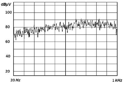
Рис. 15. Двигатель, тип 1. Спектрограмма пульсаций тока в диапазоне 20–1000 Гц
Fig. 14. Permanent work of thruster, type 1. Current ripples. Low frequency – 29 kH, amplitude – 1,2 A
Fig. 15. Thruster, type 1. Current ripples spectrogram in range 20–1000 H
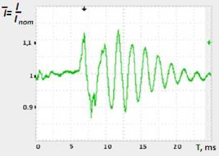
Рис. 16. Стационарная работа двигателя, тип 1. Пульсации тока. Высокая частота – 515 кГц, размах – 1,2 А
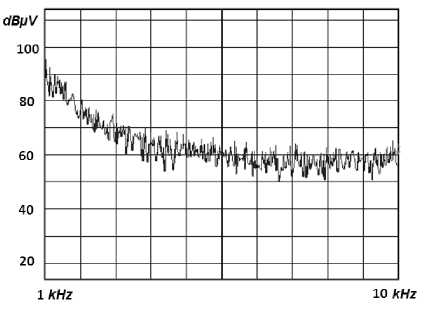
Рис. 17. Двигатель, тип 1. Спектрограмма пульсаций тока в диапазоне 1–10 кГц
Fig. 16. Permanent work of thruster, type 1. Current ripples. High frequency – 515 kH, amplitude – 1,2 A
Fig. 17. Thruster, type 1. Current ripples spectrogram in range 1–10 kH
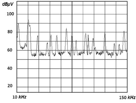
Рис. 18. Двигатель, тип 1. Спектрограмма пульсаций тока в диапазоне 10–150 кГц
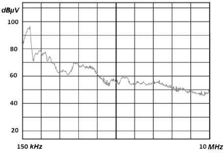
Рис. 19. Двигатель, тип 1. Спектрограмма пульсаций тока в диапазоне 150 кГц – 10 МГц
Fig. 18. Thruster, type 1. Current ripples spectrogram in range 10–150 kH
Fig. 19. Thruster, type 1. Current ripples spectrogram in range 150 kH – 10 MH
Ripples, thruster type 2
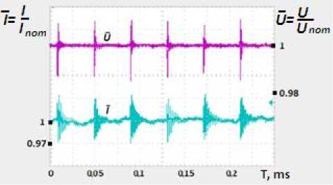
Рис. 20. Двигатель, тип 2. Стационарная работа.
Частота – 27 кГц, размах – 1,1 А
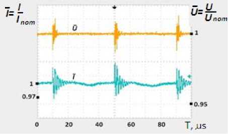
Рис. 21. Двигатель, тип 2. Стационарная работа
Fig. 20. Permanent work of thruster, type 2. Frequency – 27 kH, amplitude – 1.1 A
Fig. 21. Thruster, type 2. Permanent work
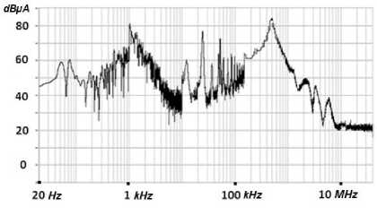
Рис. 22. Двигатель, тип 2. Спектрограмма пульсаций тока в диапазоне до 10 МГц
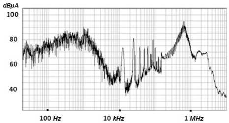
Рис. 23. Двигатель, тип 2. Спектрограмма пульсаций тока в диапазоне до 1 МГц
-
Fig. 22. Thruster, type 2. Current ripples spectrogram up
-
Fig. 23. Thruster, type 2. Current ripples
to 10 MH
spectrogram up to 1 MH
Ripples, thruster type 3
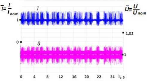
Рис. 24. Двигатель, тип 3. Пульсации в стационарной работе
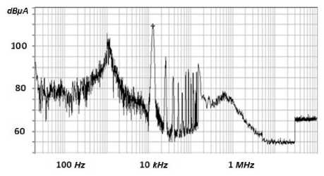
Рис. 25. Двигатель, тип 3. Спектрограмма пульсаций тока в стационарной работе в диапазоне 20 Гц – 30 МГц
Fig. 24. Thruster, type 3. Current ripples in stationary mode
Fig. 25. Thruster, type 3. Current ripples spectrogram in stationary mode in range 20 H – 30 MH
Analysis of measurement results. According to the data presented above in Fig. 4–25, it is possi- ble to evaluate the parameters of transient processes when starting and stopping type 1–3 thrusters and the parameters of ripples. These parameters are presented in Table 3.
Characteristics of system PPU- thruster
Table 3
|
Characteristics of system PPU- thruster |
Type of thruster |
||
|
Transient Processes |
1 |
2 |
3 |
|
Starting |
|||
|
Starting current as a fraction of the rated current consumption |
1,13 |
1,0 |
1,02 |
|
Starting current duration, ms |
9 |
14 |
16000 |
|
Starting current change rate, A/ms |
0,1 |
0,00145 |
0,005 |
|
Stopping |
|||
|
Stopping current duration, ms |
1 |
0,12 |
0,35 |
|
Stopping current change rate, А/ms |
0,04 |
0,15 |
0,92 |
|
Reverse surge amplitude as a fraction of the rated current consumption |
– |
– |
0,412 |
|
Ripples |
|||
|
Starting stage |
|||
|
Low frequency, kHz |
– |
– |
0,85 |
|
Range of fractions of the rated current consumption |
0,784 |
||
|
High frequency, kHz |
– |
– |
25 |
|
Range of fractions of the rated current consumption |
0,353 |
||
|
Permanent work |
|||
|
Low frequency, kHz |
29–30 |
– |
1,2 |
|
Range of fractions of the rated current consumption |
0–113 |
0,647 |
|
|
High frequency, kHz |
500 |
27 |
– |
|
Range of fractions of the rated current consumption |
0,113 |
0,073 |
|
Analysis of data presented in Table 3 shows that the features of the PPU-thruster system significantly depend on the type of thruster and PPU used. The following features can be noted:
– starting currents for all three types of thrusters are approximately equal to the rated current consumption, that is, the starting overshoots are relatively small;
– the rate of change of the starting current for a type 1 thruster is maximum (20–70 times) higher than for thrusters 3 and 2, but since its value is insignificant, it is possible to expect that this feature will not be a problem for the spacecraft power supply system;
-
– thrusters of type 1 and 2 reach an approximately stationary level of current consumption in a time of the order of 10 s, while a thruster of type 3 is much slower (by about 3 orders of magnitude);
-
– the duration of stopping current in the order of magnitude for thrusters of all three types is comparable;
-
– the rate of current change at stopping is maximum for the thruster of type 3 and significantly exceeds that in comparison with thrusters of types 1 and 2, in particular, in comparison with the thruster of type 1 23 times;
-
– reverse current surges are characteristic only for a system with a type 3 thruster, while the amplitude reaches 41 % of the rated current consumption;
-
– when the thruster of type 3 is started, low-frequency pulsations occur, apparently associated with the peculiarities of the output of this thruster to the nominal mode (perhaps this phenomenon is due to the development of a plasma discharge with the simultaneous charging of internal capacitive filters in the PPU). These ripples have a significant range, comparable to the rated current consumption - 78% of rated current. The duration of this mode is up to 40 ms. High-frequency ripple in this mode also has a significant range – 35 % of rated current;
-
– in permanent operation, the ripple range for type 1 and type 2 thrusters is relatively small and does not exceed (10–11) % of the rated current consumption. For a type 3 thruster, the low-frequency oscillation range is higher and amounts to 65 % of rated current.
It should be noted that all the listed characteristics of the thruster -PPU combination as an energy consumer were obtained without the use of any additional filters and when powered from technological sources. When powered from the standard power supply system (PSS) of the spacecraft, the results may differ depending on the construction of the PSS, power supply circuits, the presence of additional filters, etc. Therefore, the data obtained are preliminary in nature and require clarification during complex tests of the PSS -PPU-thruster. It is advisable to carry out such tests for each new type of thruster, control device and power supply. At the same time, despite the preliminary nature, the results obtained are of interest in the integrated design of spacecraft systems since they give a general idea of the electrical characteristics of one of the most powerful onboard consumers. As follows from the above, a system based on a type 3 thruster presents the greatest difficulty in linking it with the spacecraft power supply system, due to the significant switching power, reverse current surges during stopping, a significant range of ripple amplitude both at starting and in permanent operation, which requires a search for optimal connection schemes and control algorithms for the thruster subsystem.
Conclusion. The results of experimental studies of the electrical characteristics of the thruster-PPU combination for three types of equipment are presented. The parameters of transient processes when starting and stopping thrusters have been determined, as well as the parameters of ripples, both in permanent operation and during transient processes. It is shown that the greatest difficulties can arise during the operation of high-power thrusters. In particular, the starting current for the thruster can be up to 100% of the rated current with the duration of reaching the permanent mode up to 16 s. There is a reverse surge current when the thruster of this type is stopped. The rate of change of current when the thruster type 3 is stopped is maximum, the range of low-frequency ripples in permanent operation is up to 65% of the rated current. The results obtained are important in the integrated design of spacecraft, in particular, when coordinating the parameters of the power supply system and the correction system. The expediency of complex tests of the PSS-PPU-thruster for each new type of thrusters, control and power devices is noted.
References Experimental investigations of a plasma thrusters and its power processing units performances like an electric load of a spacecraft’s power condition system
- Lev D., Myers R. V., Lemmer K. M. et al. The Technological and Commercial Expansion of Electric Propulsion in the Past 24 Years. 35th Electric Propulsion Conference. IEPC-2017-242. Geor-gia Institute of Technology. USA, October 8–12, 2017.
- Vorontsov V. V., Kostin A. N., Lovtsov A. S. et al. Development of KM-60 Based Orbit Con-trol Propulsion Subsystem for Geostationary Satellite. Procedia Engineering. 2017, Vol. 185, P. 319–325.
- Garcia V., Lamoureux E., Andersson B. et al. EP System Development and Functional Valida-tion Tests for Electra GEO Satellite. 36th International Electric Propulsion Conference. IEPC-2019-A288. Vienna, Austria. September 15–20, 2019. 14 p.
- Ermoshkin Yu. M., Yakimov E. N. On the concepts of the station keeping and geostationary orbit injection thruster’s application. Proceedings of XVI International conf. “Aviation and Space”. Moscow, 2017, Nov. 20–24, P. 92–93.
- Ermoshkin Yu. M., Kochev Yu. V., Volkov D. V. et al. Design of a multifunctional electric propulsion subsystem of the spacecraft. Siberian journal of science and technology. 2020, Vol. 21, No. 2, P. 233–243. Doi: 10.31772/2587-6066-2020-21-2-233-243.
- Kryuchkov P. A., Ermoshkin Yu. M., Vavilov A. V. et al. [Agreement of electric interfaces of the electric power subsystem and the orbit raising propulsion subsystem]. Elektronnyye i elektromek-hanicheskiye sistemy i ustroystva. Tomsk, 2020, P. 52–54. (In Russ.)
- Gladuchenko V. N., Galaiko V. N., Gordeev K. G. et al. Modern status and future directions of evolution of power processing units for electric plasma thrusters. Electronic and electromechanical systems and devices. Scientific papers, JSC “NPC “Polus”. Tomsk Polytechnic University Press, 2016, P. 59–65.
- Eric Bourguignon, Stéphane Fraselle. Power Processing Unit activities at Thales Alenia Space in Belgium. Space prop. Conf. 2018, Seville, Spain, 14–18 May 2018, 8 p.
- Mallmann A., Forrisi F., Mache E. et al.High Voltage Power Supply for T5 Gridded Ion Thrust-er. 36th International Electric Propulsion Conference, IEPC-2019A512. Vienna, Austria, September 15–20, 2019, 7 p.
- Ermoshkin Yu. M., Galaiko V. N., Kim V. P. et al. [Specifics of transients in the discharge cir-cuit during the SPT-140D plasma engine starting]. Vestnik Moskovskogo Aviatsionnogo Instituta. 2017, Vol. 24, No. 4, P. 80–88. (In Russ.)
- Yermoshkin Yu. M., Volkov D. V., Yakimov E. N. On the concept of “all electric propulsion spacecraft”. Siberian Journal of Science and Technology. 2018, Vol. 19, No. 3, P. 489–496. Doi: 10.31772/2587-6066-2018-19-3-489-496.
- Kochev Yu. V., Ermoshkin Yu. M, Merkuryev D. V. et al. [The new technical solutions to be implemented to ground experimental development of an SC orbit raising and orbit correction elec-tric propulsion]. Aktualnyye voprosy proyektirovaniya avtomaticheskikh kosmicheskikh apparatov dlya fundamentalnykh i prikladnykh nauchnykh issledovany. 2017. Iss. 2, P. 300–306. (In Russ.)
- Baranov S. V., Plokhikh A. P., Popov G. A. et al. Determination of Electromagnetic Emission from Electric Propulsion Thrusters under Ground Conditions. 35th International Electric Propulsion Conference. IEPC-2017-167. Georgia Institute of Technology, USA, Oct. 8–12, 2017, 8 p.
- Nikipelov A. V., Simanov R. S., Ermoshkin Yu. M. et al. [Electric propulsion firing tests bench at JSC “ISS”]. Naukoyemkiye tekhnologii. 2016, Vol. 17, No. 8, P. 61–65. (In Russ.)
- Jackson J., Miller S., Cassidy J. et al. 13 kW advanced electric propulsion flight system devel-opment and qualification. 36th International Electric Propulsion Conference, IEPC-2019-A692. Vien-na, Austria, September 15–20, 2019, 19 p.
