Experimental Study of Airlift Pump Performance with S-Shaped Riser Tube Bend

Author: Abdel Fattah Mahrous
Journal: International Journal of Engineering and Manufacturing(IJEM) @ijem
Article in issue: 1 vol.3, 2013.
Free access
Airlift pump is a type of deep well pumps. Sometimes, it is used for removing water from mines or pumping slurry of sand and water or other solutions. The performance of airlift pump is affected by two sets of parameters; the geometrical and operational parameters. The geometrical parameters include pipe diameter, pump height, design of air injection system, and entrance geometry of the lifting pipe; while the operational parameters involve submergence ratio, conditions of injected air, and nature of lifted phase. Conventionally, airlift pump with bent riser tube is less efficient than that with vertically straight riser tube. However, in real life situations, the use of local riser tube bend or flexible riser tubes is considerably unavoidable. This work investigates experimentally the effects of local bends of the riser tube on the airlift pump performance. A series of experiments on a model airlift pump with three different riser tube configurations, based on the vertical position of local bends, were carried out. The local bends are in the form of an S-shaped like duct. The results showed that setting local bends of the riser tube near the air injection zone improves the airlift pump performance. However, improvement obtained in airlift pump performance is being negligible and, thus, the position of local bend of riser tube does not contribute to improvements in the performance of airlift pump.
Airlift pump, two-phase flow, bent riser tube, S-bend
Short address: https://sciup.org/15014344
IDR: 15014344
Text of the scientific article Experimental Study of Airlift Pump Performance with S-Shaped Riser Tube Bend
Airlift pumps are means of artificially lifting liquids or liquid-solid mixtures (slurries) from deep wells or vessels. Use of airlift pump has been promoted for a number of reasons such as: lower initial cost, lower maintenance, easy installation, small space requirements, simplistic design and construction, ease of flow rate regulation, and ability to handle corrosive, highly toxic and radioactive fluids. In the airlift system, air (or gas) is injected through an injection system at or near the base of a vertical pipe (the riser tube) that is partially
* Corresponding author.
E-mail address:
submerged in a liquid or slurry. Bubbles, therefore, form and expand as they rise. A two- (or three-) phase column containing air has a lower density than a column of liquid alone and consequently the mixture formed in the airlift tube rises and is expelled at the top of the pump.
Numerous publications were published related to the theoretical and experimental analysis of the airlift pump performance. Parker [1] made a comprehensive experimental study to determine the effects of foot piece design on the lifting characteristics of the airlift pump used for hydraulic transport of liquids. Two different air-injection foot piece designs were used: the air-jacket injector and the nozzle injector. The second type was placed on the axis of the riser tube just below the bottom of the airlift tube. With the air-jacket design, the discharge characteristics of the airlift pump were shown to be independent on the number and sizes of the air injection holes. On the other hand, the pumping characteristics with the nozzle injector design were shown to be improved by using nozzle injector with small orifice area. However, decreasing the total orifice area caused an increase in the pressure loss and accordingly reduced the pump efficiency. The effects of air-injection method on the airlift pump performance were experimentally investigated by Mansour and Khalil [2] and by Khalil et al. [3] . In their experimental study, they tested different injection designs under similar operating conditions. Experiments were carried out for different values of lift ratio and under different values of injection pressures. They concluded that, the initial bubble size and distribution in the riser tube could have great effects on the pump performance. The experimental results showed that the multi-orifice injectors have a significant effect on the pump performance. Khalil and Mansour [4] carried out an experimental investigation on the airlift pump performance by studying the effect of introducing a surfactant to the pumped liquid. The experimental results showed that an improvement in the pump capacity and efficiency could be obtained when using a surfactant with low concentration. The performance of a short airlift pumping system operating at low submergence ratios was investigated by Lawniczak et al. [5] . They studied the influence of riser tube diameter and injector design on the efficiency characteristics of the airlift pump. The air-injection system was designed such that the position of a cylindrical injector in a conical entrance section of the riser tube could be changed. Changing the injector position was shown to cause a corresponding change in the injector geometry parameter (ratio of water cross sectional area available at the air injection level to air injector cross sectional area). They found that the effect of air injector position, in the conical entrance of the riser tube, depends upon the riser tube diameter. For each riser diameter, this effect was mainly restricted to the small values of the injector geometry parameter, while for higher values of this parameter, the efficiency curves differ slightly. The effects of local bends of riser tube were experimentally studied by Fujimoto et al. [6] . Results indicated that setting local pipe bends before gas injector (in the suction pipe) is better for pump performance than that above the gas injector. Mahrous [7] numerically investigated the performance of airlift pump lifting solids under various geometrical and operational conditions. The parametric predictive studies showed that the solid particles volumetric concentration in the suction section of the airlift tube significantly affects the airlift pump efficiency based on solids as the main gain of the pump. On the other hand, larger diameters of solid particles and higher input airflow rates would have a negative effect on the pump performance.
It is commonly accepted that expansion of air in the riser tube of the airlift pump from the air injection pressure to the atmospheric pressure causes the two-phase air-liquid flow to distribute in a number of patterns [8]. The basic flow patterns are bubbly, slug, churn and annular flows (Fig. 1). At low air input velocity, the air phase can rise in bubbles of different and variable shape and size. This type of flow is called bubbly flow. As the input air rate increases, the smaller bubbles begin to coalesce into larger bubbles or air slugs which in essence separate the water column into the slug flow regime. The transition between these two flow regimes is termed as the bubbly-slug flow regime where small bubbles are found suspended within the liquid slugs between the larger air slugs [9]. In case of very high input air velocities, the liquid can be pushed to the wall of the tube and the air streams separate in the middle of the tube and loaded with droplets of liquid. This type of flow regime is called annular flow. In annular flow, the continuity of air along the pipe appears in the core and no liquid is being lifted. Moreover, the pressure losses and power losses of flow are extremely high. So, for airlift pumps, it is advisable to avoid the ranges of annular flow, which is characterized by poor pumping efficiency. If the difference between the air injection pressure and pressure at pump outlet, which usually is atmospheric, is very high, annular flow can occur in the upper part of the riser tube. While in the lower part, just above the air injection zone, bubbly flow is found. In such cases, the pump performance may be highly improved if the pipe diameter is enlarged at certain distances [10, 11]. This graduation of the riser tube could ensure slug flow along its height.
Having local bends in the riser tube, the main objective of this work was to experimentally study the effects of local bends position, from the air injection level, on the airlift pump performance. The presence of local bends was tested at different locations downstream the air injection section to figure out the appropriate position with regards to pump performance.
The remainder of the paper is organized as follows. Chapter 2 is devoted to the experimental work and measurements of pump performance. Chapter 3 is concerned with the experimental results and discussions. The experimental results are compared with theoretical ones in Chapter 4. Investigation of gas holdup distributions in the airlift pump with bent riser tube is also presented in Chapter 4. The main conclusions of the presented work are drawn and presented in Chapter 5.
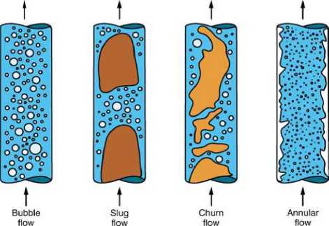
Fig. 1. Flow regimes for gas-liquid two-phase flow in a vertical pipe [12] .
2. Experimental Set-up
In order to experimentally investigate the performance of airlift pump having local bends in the riser tube, a testing airlift pump model was designed and constructed to carry out the course of this research. The present experimental set is shown schematically in Fig. 2. The body of the airlift pump consists of a vertical pipe that is composed of riser and suction pipes, (1) and (2), respectively, in addition to a water reservoir (3), into which the suction pipe was inserted. The free surface level of the water in the water reservoir, measured from the air injection level, defines the submerged length. This length divided by the riser tube length defines the submergence ratio. The liquid level in the water reservoir is controlled so that the required submergence ratio can be obtained. The pump submergence is kept unchanged during the test by regulating the water level in the water reservoir. Compressed air, which is supplied to the pump from the compressor air-tank (10) through an air-supply line (11), airflow control valve (8), and an airflow meter (9), is injected into the riser pipe (1) through an air injection system (12). The airflow rate is measured using a calibrated sharp-edged orifice meter (9) connected to a mercury U-tube manometer (5). Another U-tube manometer with mercury as a measuring fluid (6) is used for measuring the air pressure upstream of the orifice plate. After injecting air through the air injection system, it merges into the water and forms a two-phase air-water mixture. The two-phase air-water has less average mass density than the pure water outside the lifting pipe, in the water reservoir, and therefore it is elevated upward in the riser tube and discharged into an air/water separator. The air is freed into the atmosphere while the water is collected for measuring its volume flow rate through water collecting tank (4). Water is then allowed to flow back to the water reservoir (3). The length of suction pipe (2) was chosen such that the injected air does not bubble back into the water reservoir.
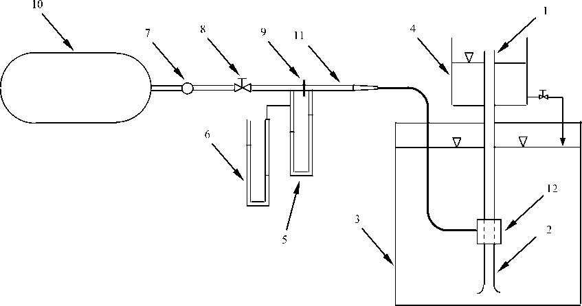
The suction part of the airlift tube is a vertical rough iron pipe having a uniform cross section of 19.05mm bore, with an outside diameter of about 24mm, and a length of 210mm. The airlift pipe is fixed vertically in the middle of the water reservoir (3) that was made from iron with side’s dimension of 1000x1000x900mm. The air-injector (12) is an air-jacket type placed on the axis of the conveying pipe. In the air-jacket design, there are 64 injection holes, each of 2mm diameters. These holes were drilled uniformly through the perimeter of the airlift tube in eight rows and eight columns (8x8) and at 15mm distance between holes. A larger iron tube of 76.2mm inside diameter is surrounding the drilled-pipe section. The two sections, inside and outside tubes, were flanged together to form a manifold for the distribution of the compressed air. According to this design, the air is uniformly distributed around the lifting tube so that the radial momentum of the air is balanced with each other.
In order to investigate the effects of local bends of the riser tube section on the airlift pumping characteristics, three riser tube models of 900mm height each were designed and tested. Details of these models configuration are shown in Fig. 3 along with data in table 1. The local riser tube bends were set in the lower part of riser tube model M1 and in the upper section of the riser tube model M3.
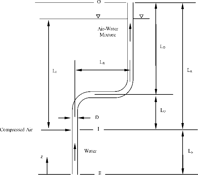
Fig. 3. Configurations of the tested riser tube.
Table 1. Test models of the riser tube.
|
Tube Length, mm |
|||
|
Test Model |
L U |
L B |
L D |
|
M1 |
180 |
120 |
720 |
|
M2 |
420 |
120 |
480 |
|
M3 |
650 |
120 |
250 |
3. Experimental Results and Discussions
The results of lifting pure water using the airlift pump with the riser tube models M1, M2, and M3 are presented in Fig. 4 at 63% submergence ratio. Fig. 4 shows a typical example of the water pumped rate (water volumetric flux, jL= QL/A, where A is the uniform cross sectional area of riser tube) as a function of the airsupplying flow rate calculated at the standard atmospheric conditions (air volumetric flux, jGa= QGa/A). The airflow rate was systematically varied and the corresponding water flow rate was measured. As illustrated in Fig. 4, for a constant value of submergence ratio and for the investigated range of airflow rate, the water flow rate increases by increasing the airflow rate. This behaviour continues until a limiting point is reached, where the water flow rate reaches a maximum value. Further increase in the airflow rate causes a decrease in the water discharge rate. This reduction in the water discharge rate can be attributed to the fact that the flow pattern in the riser tube at higher airflow rates tends to become annular. At lower airflow rates, however, slug flow is dominated in the airlift tube. In the bubbly-slug flow regime, right before the optimum point, the water pumped rate is directly proportional to the airflow rate [5]. Results in Fig. 4 also show that, in order to achieve a pumping action of the airlift system, a minimum airflow rate is required. This minimum airflow rate depends upon the corresponding submergence ratio and its value may be read at the points of intersection of various curves with the air volumetric flux axis.
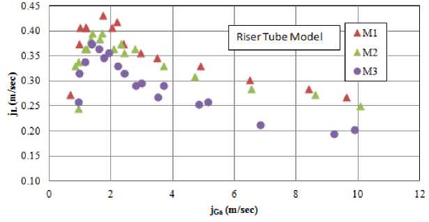
Fig. 4. Effects of riser tube configuration on water discharge rate.
The effects of the position of local bends of the riser tube on the water pumped rate are shown in Fig. 4 for the three tested configurations of the riser tube. It is clear that, for low airflow rates, the water discharge rate is not appreciably influenced by the position of the local bends. For higher airflow rates, the pump output rate is slightly increased with the airlift model M1 as compared to that of Models M2 and M3. This behavior could be attributed to the fact that at low airflow rates, bubbly flow regime dominated in the riser tube close to the air injection zone, while at higher airflow rates, the flow pattern tends to become annular. Setting local tube bends of the riser tube after the air injection section does not significantly contribute to pumping pressure loss in the riser tube as the flow regime still bubbly.
Results in Fig. 4 further illustrate that the water pumped rate in case of model M1 continues to increase beyond the value of air flow rate corresponding to the point of maximum water pumped rate in case of M3. Moving the local tube bends to the top part of the riser tube is shown to reduce, to some extent, the rate of pumped water. The reason for such a trend may be attributed to the acceleration losses owing to the expansion of air in the riser tube. Expansion of air is accompanied by large values of air void fraction near the top of the riser tube. As depicted in Fig. 4, it is apparent that the airlift pump becomes more efficient when setting the local bends near the injection zone in the lower part of the riser tube.
An important parameter for the applications and comparisons of the airlift pumps with different designs is the mass of water pumped per mass of air injected, measured at standard conditions. In the literature, this parameter was termed as effectiveness of the airlift pump. It expresses the mass of air required to lift a unit mass of water through the non-submerged part of the riser tube. Fig. 5 shows the variation of the airlift pump effectiveness with the air volumetric flux for different riser tube models of the airlift pump. It can generally be seen that as the air volumetric flux increases, more water is pumped but with a much lower pump effectiveness. The results displayed in Fig. 5 demonstrated that the local tube bends slightly improves the pump effectiveness in case of airlift pump with riser tube model M1.
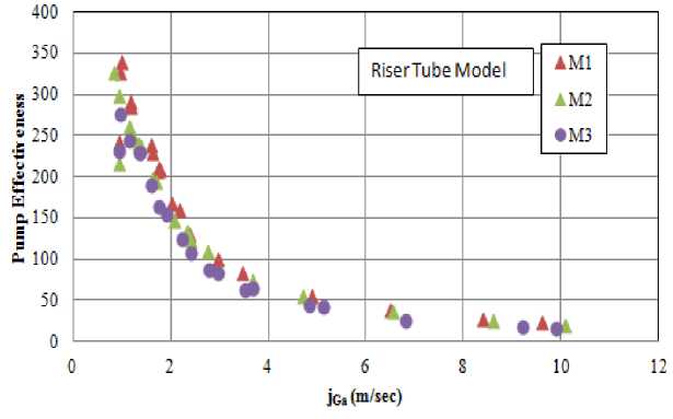
Fig. 5. Effects of riser tube configuration on airlift pump effectiveness.
It has to be elucidated that common sources of errors in the measured parameters were found in the measurements of pressure difference across the orifice plate, the upstream air pressure, the submergence ratio, and the water flow rate. They mainly came from both the unsteady airflow from the air compressor, which, in turn, is due to the fluctuating pressure in the air reservoir, and the flow oscillation in the riser tube. Flow oscillation in the riser tube is caused by the harmonic oscillation of air bubbles while ascending in the riser tube. The uncertainty analysis was done for the water flow rate, airflow rate, and the effectiveness of the airlift pump. In the present measurements, it was found that the error of measured water flow rate was about ±0.5%. The uncertainty in the upstream air pressure was found to be about ±3.3kPa. The head difference across the orifice section gave an error of about ±0.3cm water. The resulting uncertainly in the airflow rate was found to be about +3.5%. The uncertainty estimation in water and airflow rates results in an uncertainty in the lifting effectiveness of about ±3%. Furthermore, a 1mm diameter pressure tap could introduce an error of less than 1% of the dynamic pressure, compared with the ideal tap diameter of 0.25mm.
4. Comparison with Theory
In order to understand the expansion of air phase in the bent riser tube, a numerical model of airlift pump performance was developed and validated. Numerous studies up-to-date have offered different calculation methods of airlift pump performance based on the principles of theoretical treatment. Among others, Clauss [13] , Boës et al. [14] , Yoshinaga and Sato [15] , Margris and Papanikas [16] , and Hatta et al. [17] developed more reliable theoretical analysis for the calculations of airlift pumps. Each of these models allowed a general calculation for the pumping action required by the airlift pump. In the present work, a numerical analysis of the performance of airlift pump based on the principle of momentum balance is presented under steady state operating conditions. The airlift pump performance is studied according to the analysis of Yoshinaga and Sato [15] . The assumptions made for the mathematical formulation of the airlift mechanism were: compressible and ideal gas flow for the air phase, the planes of equal velocity and equal pressure are normal to the pipe axis (this makes the problem one-dimensional), no exchange of mass between phases, and isothermal flow for all phases. The assumption of isothermal flow is justified only if the phases flow slowly through the airlift tube so that a continuous heat exchange with the environment is no longer possible, Margaris and Papanikas [16] .
The body of the airlift pump illustrated in Fig. 3 consists of two main parts. The first lower part is a suction pipe of length (LS) between the bottom end (level E) and the air injection ports (level I), while the second part is the riser tube of length (LR) between the compressed air and discharge ports. A model S-shaped bend tube section of straight tube length (LB) was set at some points on the riser tube in order to investigate its effect on the pump discharge rate. The ratio between the riser tube section length upstream of the S-bend section (LU) and the total riser tube length (LR) is termed as (γ). Compressed air is injected at a water depth of (LI). The ratio between the submerged depth (LI) and the total riser tube length (LR) is the pump submergence ratio (α).
Applying the concept of momentum balance to a control volume bounded by the pipe wall and pipe cross sections at the suction and discharge levels (levels E and O, respectively) results in the momentum equation.
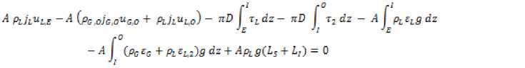
Here ρ is the density, j is the volumetric flux, u is the velocity, A is pipe cross-sectional area, D is pipe diameter, τ is the shear stress, ε is the volumetric fraction, P is the pressure, and g is the acceleration due to gravity. The subscripts L and G denote the liquid and gas phases, respectively. In addition, the subscript 2 refers to the two-phase air-water mixture.
In Equation 1, the first and second terms denote the momentum of flow that enters through E and leaves through O, the third and fourth terms denote the frictional forces in the suction and riser tubes, respectively, the fifth and sixth terms denote the weight of the water phase (in the suction tube) and the weight of the two-phase air-water mixture (in the riser tube), and the seventh term denotes the hydrostatic pressure force of the surrounding water, acting at the bottom end of the pipe at section E. It is noted that the interaction forces between phases, such as the drag and virtual mass forces, appear in the mathematical formulation only if the conservation equations of mass and momentum are applied for each phase separately. Here, the mean velocity of the flow component “i” (i is air or water) is given as
4i
л
Ei
Since both the air pressure and airflow rate vary throughout the pump, owing to the expansion of air, the frictional and body forces in the riser tube section cannot be estimated at the mid section of the riser tube and, therefore, the riser tube should be divided into a number of short segments in the flow direction. The length of each segment is chosen such that the nodes pressure ratio for any segment is the same for all segments. Assuming that the pressure distribution for each segment is linear, the frictional pressure gradient at such a segment and the flow local conditions are calculated at the middle of this segment. The terms of frictional and body forces in the momentum equation, Equation 1, are then calculated using step-by-step integration procedure throughout the riser tube.
An iterative solution is required for the calculation of air and water volumetric ratio and also for the other flow parameters that are involved in the momentum equation. During the calculations, the air temperature at the injection point is assumed to be the same as the temperature of the water. Moreover, the temperature gradient is neglected through the riser tube. Therefore, an isothermal expansion of gas from the air injection pressure to the pump outlet pressure (PO) is applied. Performing the momentum balance over the entire length of the airlift tube, the airflow rate (jG,O) aimed to achieve a specific gain of water output rate (jL) can be numerically predicted. The numerical computations are also necessary for calculating the variations in air and water conditions throughout the individual sections of the airlift tube. Detailed information about the definition of different terms of Equation 1 can be found in the analysis of Yoshinaga and Sato [15] and in the research work of Mahrous [18] .
In an attempt to verify the validity of the present modelling approach, the predicted results obtained by the developed numerical model were compared with the current experimental data and with measurements of
Fujimoto et al. [6] , in case of riser tubes with local bends, as well as with data measured by Yoshinaga et al. [15, 19] for vertically straight riser tubes. The theoretical predictions and the experimental data of the performance of airlift pump while lifting pure water have been compared through Fig. 6, Fig. 7, and Fig. 8 at different values of submergence ratio (α). As illustrated in Fig. 6, Fig. 7, and Fig. 8, the performance of airlift pump is well predicted by the developed numerical code over the entire range of presented submergence ratios and in both straight and bent riser tube configurations. The comparison between the numerical and measured data, thus, demonstrates a high degree of agreement that is sufficient to justify the use of this simulation tool for parametric predictive studies.
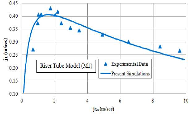
Fig. 6. Comparison of numerical results calculated based on present theoretical model with experimental data of riser tube model M1 at 63% submergence ratio.
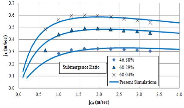
Fig. 7. Comparison of numerical results calculated based on present theoretical model with experimental data by Fujimoto et al. [6] . Experimental conditions are: local bends on the riser section, D = 18 mm, LR=2.4m, LS=0.8m, LB=0.61m, and γ = 0.1833.
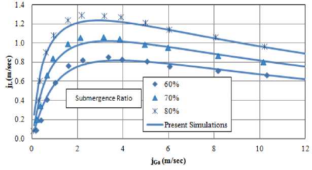
Fig. 8. Comparison of numerical results calculated based on present theoretical model with experimental data by Yoshinaga et al. [15 , 19] . Experimental conditions are: D=26 mm, LR=6.74m, and LS=1.12m.
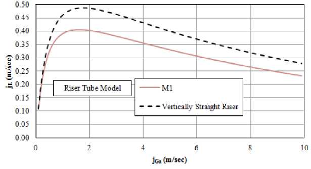
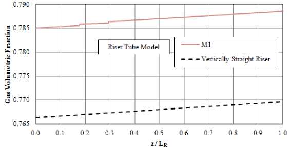
The effect of the bend section of the riser tube on the pump discharge rate at 63% submergence ratio is predicted and plotted in Fig. 9. The S-bend section for riser tube model M1 is compared against the vertically straight riser tube. As depicted in Fig. 9, the S-bend section of the riser tube has a negative effect on the pump performance. This is definitely attributed to the increased head loss due to wall friction and local tube bends in case of bent riser tube. The development of the air phase in the riser tube of straight and bent tube models is shown in Fig. 9b in terms of the variation in gas holdup at jGa=5m/sec. As depicted in Fig. 9b, the gas holdup is gradually increasing as the air rises in the riser tube. For the bent riser model, the development of the air phase through the straight horizontal part of the S-shaped section is almost flat with abrupt changes at local bends. Fig. 9b illustrates that the presence of local bends of riser tube increases the acceleration or pumping loss of flow and therefore the air volumetric fraction is higher than that of vertically straight riser tube.
Fig. 10 illustrates variations in the air volumetric fraction along the riser tubes of different riser tube models at a constant value of air volumetric flux (jGa). As shown in Fig. 10, the variation in the air volumetric fraction due to the expansion of air in different riser tube models from air injection pressure to pump exit pressure is not considerable. Although local bends of different riser tube models exhibit a sudden increase in the air holdup, all riser tube models exhibit almost the same flow regime at pump exit section.
(a)
(b)
Fig. 9. Effects of the local bends of riser tube on water discharge rate (a) and on air volumetric fraction at jGa=5m/sec (b) at α=63%.
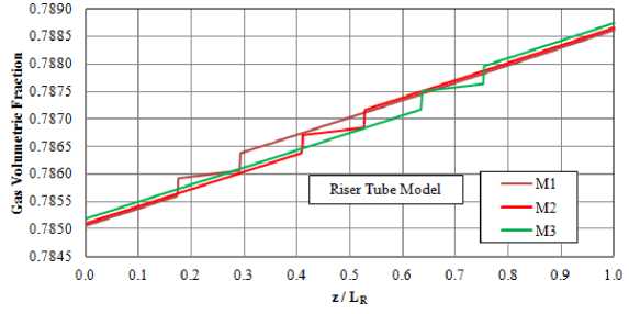
Fig. 10. Variation of air volumetric fraction along different riser tube models at jGa=5 m/s and α=63%.
5. Conclusions
The performance of airlift pumps depends mainly on two groups of parameters. The first group is the geometrical parameters such as pipe diameter, pump height, design of injection system and entrance geometry of the lifting pipe, while the other group is the operational parameters such as submergence ratio, injected gas flow rate and its corresponding pressure, and nature of lifted phase. This research presents an experimental study of the effects of local bends of the riser tube on the airlift pump performance. A series of experiments on a model airlift pump with different riser tube configurations, based on the position of local riser tube bends, were carried out. Although slight improvement in the water-pumping rate can be obtained when setting the S-shaped local bend section of the riser tube close to the air injection level, the effect of bend section position of the riser tube under the current working conditions has an insignificant contribution to improvements in the pump discharge rate.
References Experimental Study of Airlift Pump Performance with S-Shaped Riser Tube Bend
- Parker, G.J. The effect of foot piece design on the performance of a small diameter airlift pump. Int. J. Heat and Fluid Flow; 1980; 2(4): 245-252.
- Mansour, H., Khalil, M.F. Effect of air injection method on the performance of airlift pump. Mansoura Eng. J.; 1990; 15(2): 107-118.
- Khalil, M.F., Elshorbagy, K.A., Kassab, S.Z., Fahmy, R.I. Effect of air injection method on the performance of an airlift pump. Int. J. Heat and Fluid Flow; 1999; 20: 598-604.
- Khalil, M.F., H. Mansour, H. Improvement of the performance of an airlift pump by means of surfactants. Mansoura Eng. J.; 1990; 15(2): 119-129.
- Lawniczak, F., Francois, P., Scrivener, O., Kastrinakis, E.G., Nychas, S.G. The efficiency of short airlift pumps operating at low submergence ratios. The Canadian Journal of Chemical Engineering; 1999; 77: 3-10.
- Fujimoto, H., Murakami, S., Omura, A., Takuda, H. Effect of local pipe bends on pump performance of a small air-lift system in transporting solid particles. International Journal of Heat and Fluid Flow; 2004; 25: 996–1005.
- Mahrous, A.-F. Numerical study of solid particles-based airlift pump performance. WSEAS Transactions on Applied and Theoretical Mechanics; 2012; 7(3): 221-230.
- Shimizu, Y., Tojo, C., Suzuki, M., Takagaki, Y., Saito, T. A study on the air-lift pumping system for manganese nodule mining, in Proc. of the 2nd International Offshore and Polar Engineering Conference, San Francisco, USA; 1992; 490-497.
- Reinemann, D.J., Timmons, M.B. Predicting oxygen transfer and total dissolved gas pressure in airlift pumping. Aquacultural Engineering; 1989; 8: 29-46.
- Dedegil, M.Y. Principles of airlift techniques, in Encyclopedia of Fluid Mechanics, N.P. Chereimisinoff, Editor; 1986; Gulf, Houston, TX. p. Chapter 12.
- Nenes, A., Assimacopoulos, D., Markatos, N., Mitsoulis, E. Simulation of airlift pumps for deep water wells. The Canadian Journal of Chemical Engineering; 1996; 74: 448-456.
- Mudde, R.F. Gravity-driven bubbly flows. Annu. Rev. Fluid Mech.; 2005; 37: 393–423.
- Clauss, G.F. Investigation of characteristic data of air lifting in ocean mining (Untersuchung der kenngrőben des airlifts beim Einsatz im ozeanbergbau). Erdől-Erdgas-Zeitschrift; 1971; 87: 57-66 (In German).
- Boës, C., Düring, R., Wasserroth, E. Airlift as a drive for single and double pipe conveying plants (Airlift als antrieb für einrohr-und doppelrohr-főrderanlagen). főrdern und heben; 1972; 22(7): 367-378 (In German).
- Yoshinaga, T., Sato, Y. Performance of an air-lift pump for conveying coarse particles. Int. J. Multiphase Flow; 1996; 22(2): 223-238.
- Margaris, D.P., Papanikas, D.G. A generalized gas-liquid-solid three-phase flow analysis for airlift pump design. Trans. of the ASME, J. of Fluids Engineering; 1997; 119: 995-1002.
- Hatta, N., Fujimoto, H., Isobe, M., Kang, J. Theoretical analysis of flow characteristics of multiphase mixtures in a vertical Pipe. Int. J. Multiphase Flow; 1998; 24(4): 539-561.
- Mahrous, A.-F. Performance of airlift pumps, in Mechanical Power Engineering Dept.; 2001; Menoufiya University, Egypt.
- Yoshinaga, T., Sato, Y., Sadatomi, M. Characteristics of air-lift pump for conveying solid particles. Jap. J. Multiphase Flow; 1990; 4: 174-191 (in Japanese).
