Facade systems modal analysis in consideration its own dynamic characteristics of the frame

Author: Rybakov Vladimir Alexandrovich, Deriugin Konstantin Sergeevich, Pushkarskaya Marina Andreevna, Urmanceva Karolina Alexandrovna
Journal: Строительство уникальных зданий и сооружений @unistroy
Article in issue: 4 (89), 2020.
Free access
This article studies the degree of the wind load dynamic component influence on the bearing capacity of the hinged ventilated facade systems (HFS) of a high-rise building. The research model is a reinforced concrete building with a HFS with variable number of storeys and with constant dimensions and identical floor plans over the entire height. As a design of the HFS, a scheme based on the T-profile with a step of brackets of 600 mm vertically and a pitch of guide racks of 500 mm horizontally is adopted. The number of storeys is taken as a variable parameter of the research model. The following tasks were solved in the work: determination of the natural frequencies of the HFS as a multi-span beam; determination of natural vibration frequencies of the facade systems together with a reinforced concrete building, determination of dynamic factors, and comparison of the obtained values. As a result of the work, it was shown that when determining the bearing capacity of the HFS of a high rise building, it is impossible to consider the facade system as a separate structure from the building. A methodology for modal analysis is proposed, which allows determining refined values of the natural frequencies of a substructure vibration and dynamic factor.
Hinged ventilated facade systems (hfs), wind load, dynamic component of wind load, load bearing capacity, high rise building, enclosing structures, dynamic factor, natural frequency of vibration, modal analysis
Short address: https://sciup.org/143172526
IDR: 143172526 | UDC: 69 | DOI: 10.18720/CUBS.89.6
Text of the scientific article Facade systems modal analysis in consideration its own dynamic characteristics of the frame
The use of hinged ventilated facade systems (HFS) began a long time ago, including in Russia, about 15 years ago. This technology is being developed and improved. HFS are suitable not only for new construction, but also for reconstruction. HFS have a number of advantages compared to conventional external walls, due to their light weight, excellent thermal insulation [1], [2], durability, aesthetic shape, and fast enough structural supporting (fixing) [3]. The market, types of facade systems were studied by many experts, considering the advantages and disadvantages, types of facade systems, types of fixing, as well as comparing HFS with render systems [4], [5].
The bearing capacity of the elements of the facade system is one of the main characteristics of research. In [6], [7], we previously conducted researches on the bearing capacity, with consideration of methods for calculating thin-walled structures.
The load that has the greatest impact on the stress-strain state of the facade system is wind [8], [9]. The study, as well as analysis and addition to the existing SP 20.13330.2016 “Loads and impacts” (Russian codes) are given in [10],[11] where comparative analysis of Russian codes and others for the purpose wind load on facade systems is represented. The work [12] was also taken into account, and in particular, the hypothesis about the calculation of a structure composed of thin-walled open-profile Rybakov, V.A.; Deriugin, K.S.; Pushkarskaya, M.A.; Urmanceva, K.A.
Facade Systems Modal Analysis in Consideration its Own Dynamic Characteristics of the Frame;
rods using seven nodal unknowns. After calculating the multi-span beam according to two limiting states, the author of the article determines the most unfavourable effect of the wind load, and gives recommendations on the maximum permissible deformations of the facade system.
The impact of the wind load is a topic for discussion, as well as study, especially for high rise buildings [13], as well as its effect on the bearing capacity [14], [15], [16], [17], [18].
Heat conducting and numerical simulation of ventilated facades climate are presented in [19].
The goal of this research: to determine the degree of influence of the wind load dynamic component on the load bearing capacity of the hinged facade system of high-rise buildings.
2 Test Methods
As a research model, we consider a reinforced concrete building of variable number of storeys (floor height is 3m) with constant dimensions (figure 1) and identical floor plans over the building height. As a variable parameter, we take the number of storeys.
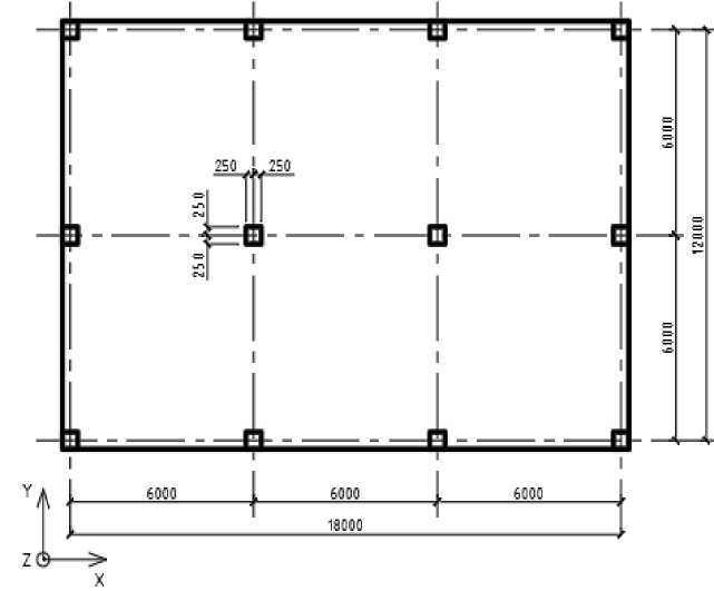
Figure 1 – Floor plan of the considered building
Building dimensions: 18х12 (m); column cross-section: 500х500 (mm); slab thickness: 300 mm; floor height: 3 m; concrete grade: В25 (Russian codes). The finite element model of the frame is represented on figure 2.
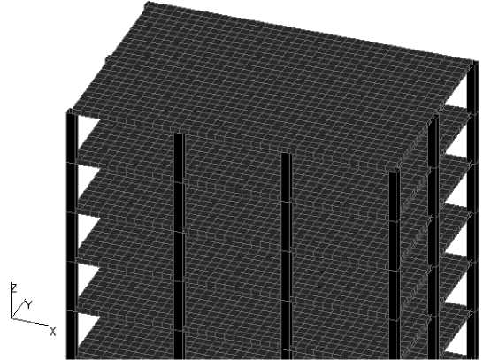
Next, we add to the existing design scheme a brick wall structure that is hingely supported to the slabs and columns of each floor around the perimeter (figure 3).
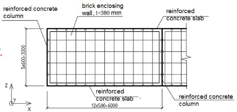
Figure 3 – Fragment of the general design scheme with the enclosing brick wall
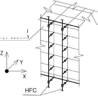
As a substructure of a HFS, we take a scheme based on a T-profile with a space between supporting brackets of 600 mm vertically and a space between guide beams of 500 mm horizontally (figure 4). To support the HFS to the brick wall, there was designed a 380 mm thick hollow brick wall.
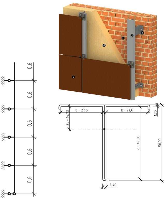
Figure 4 – The design scheme of substructures
The weight of the HFS structure is the sum of the weights of the guide beam, support bracket and extension beam (1.58 kg/m) and fiber cement facade panels (15.6 kg/m2).
A fragment of the resulting design scheme is represented on figure 5.
Brick enclosing wall , t=380mm
reinforced concrete slab
Figure 5 – Fixing the facade system to the wall and slab
Next, for the calculation scheme, we will make a modal analysis and determine the first few natural frequencies of vibrations.
3 Calculations results and their analysis
The modal analysis of the HFC together with the monolithic frame and brick walls gave the following results of natural frequencies (table 1):
Table 1 – Natural frequency values, Hz
|
Natural mode number |
The value of the natural frequency f i with the number of storeys |
|
|
25 |
50 |
|
|
1 |
3.216* |
1.113* |
|
2 |
3.752 |
2.513* |
|
3 |
4.374 |
4.119 |
*values of natural frequencies that are less than the limiting frequency
Calculation of the normative value of wind load pulsation component w p at the equivalent height z e depends on the values of the natural frequencies f i , Hz and their ratio with the limiting value of the natural frequency f lim , Hz.
Next, to assess the significance of the results, we determine the limiting values of the natural frequencies.
Limiting natural frequency value f lim , Hz, should be determined with using limiting period T g,lim :
f = lim
( w 0 k ( z e ) 7 f )1/2
,
9407 , g ,lim
where T g,lim = 0.0077 – according SP 20.13330.2016 (Russian codes) from the logarithmic decrement δ, which was adopted 0.15 in the paper; k ( z эк ) is coefficient taking into account the change in wind pressure for a height z e , which for buildings and structures is equal to 0.8h, h – is the height of the building.
The coefficient k ( z e ) for heights z e ≤ 300 m is determined by the formula
k(Ze) = kio(Ze)2a, where ze is the equivalent height; k10 = 1.0 и α = 0.15 are determined by the table 11.3 SP 16.13330 (Russian codes) depending on the type of locality; γf is the load safety factor of 1,4.
Rybakov, V.A.; Deriugin, K.S.; Pushkarskaya, M.A.; Urmanceva, K.A.
Facade Systems Modal Analysis in Consideration its Own Dynamic Characteristics of the Frame;
Thus, the limiting values of the natural frequency are presented in table 2.
Table 2 – The limiting values of the frequency of natural vibrations
|
Number of storeys |
Height of building h , m |
Equivalent height h e , m |
k ( z e ) |
The limiting values of the frequency f lim , Hz |
|
25 |
75 |
60 |
1.601 |
3.583 |
|
50 |
150 |
120 |
1.971 |
3.975 |
The calculation of the limiting value of the natural frequency f lim given in table 2 was carried out according to the last re-release of SP 20.3330.2016 (2018, March). In an earlier version of the SP 20.3330.2016, f lim was determined according the table depending on the decrement and wind region (for the calculation f lim = 3.4 Hz).
If the natural frequencies of the enclosing elements (their load-bearing structures and their fixing elements) are less than their limiting values, the calculated values of the peak wind load should be clarified based on the results of the dynamic calculation of the indicated system of structural elements. Therefore, it becomes necessary to take into account the dynamic coefficient ξ.
From table 1 it follows that for each of the design schemes the first frequency is less than the limit value. For fixing elements and their joints, it is necessary to take into account peak positive w + and negative w- effects of wind load:
-
1) for all structures (and their bearing elements) for which
f 1 < f lim < f 2 by formula 3.
w + ( - ) = w 0 k ( z e )[1 + ^ • Z ( z e )1 • c p , + ( - ) -V + ( - ) , (3)
where c ,are the peak values of the aerodynamic coefficients of positive pressure (+) or (-); v+( 4are correlation coefficients of the wind load corresponding to positive pressure (+) and negative (-); the values of these coefficients are given in table. 11.8 SP 16.13330 (Russian codes) depending on the area of the enclosing structure A, with which the wind load is collected; v+(_ } = 1.0 ; f i, f 2 are first and second natural frequencies, correspondingly; ζ(z e ) is coefficient of wind pressure pulsation; ξ is dynamic factor; ν is the spatial correlation coefficient of wind pressure pulsations.
Aerodynamic coefficients c and c for HFS and translucent structures are determined based on the results of model tests of structures in air tunnels.
In the frame of this paper, the coefficients were adopted as for stand-alone rectangular buildings in the plan according to Appendix B of SP 20.3330.2016.
-
2) for structures in which the 2nd, 3rd, etc. natural frequencies are less than the limiting frequencies, it is necessary to perform a dynamic calculation taking into account the s first vibration modes.
The number should be determined from the condition: f s < f lim < f s+1 .
In this case:
W p = ( w p, ,1 + w p ,2 + ... + w p , . )1/2 (4)
The dynamic coefficient ξ is determined according to figure 11.1 SP 16.13330.2016 (Russian codes) depending on the logarithmic decrement δ and the dimensionless period T g,1 , which is determined by formula 5:
( w 0 k ( z e )7Г )1/2
T- = g '1 940f
The design scheme of a building with 25 storeys corresponds to the first case, and with 50 storeys to the second one, when 2 natural frequencies are taken into account.
The values of the dynamic coefficients obtained by calculation (which must be taken into account when calculating the HFS stress-strain state) are represented below.
Table 3 – Dynamic factors
|
25 storeys |
50 storeys |
||
|
f i , Hz |
ξ i |
f i , Hz |
ξ i |
|
3.216 |
1.3 |
1.113 |
1.7 |
|
- |
- |
2.513 |
1.4 |
It is appropriate to compare the obtained frequencies with the first natural frequency, which can be obtained by considering the design scheme of the substructure as a multi-span beam with stationary supports (figure 4), equal to f HFS = 8.07 Hz.
This value exceeds the limit values by 2 or more times (table 2). Consequently, in [24], the eigen dynamic characteristics were not taken into account, that is the dynamic factor was taken equal to 1.0.
Thus, when calculating the wind load according to the codes, it is incorrect to consider the system of guide beams separately as a multi-span beam on stationary supports.
4 Conclusions
-
1. It is shown that when determining the bearing capacity of the HFS of high-rise buildings, it is incorrect to consider the facade system as a separate structure from the building due to the presence in the natural frequencies values spectrum not exceeding the limiting frequencies.
-
2. A methodology for modal analysis is proposed, which allows to determine specified values of the natural frequencies of vibrations of the substructure and dynamic coefficient, correspondingly
-
3. The range of values of dynamic factor from 1.3 to 2.2 is obtained for 25-50 storey buildings, correspondingly.
References Facade systems modal analysis in consideration its own dynamic characteristics of the frame
- Sanjuan, C., Suárez, M.J., González, M., Pistono, J., Blanco, E. Energy performance of an open-joint ventilated façade compared with a conventional sealed cavity façade. Solar Energy. 2011. 85(9). Pp. 1851-1863. DOI: 10.1016/j.solener.2011.04.028
- Shameri, M.A., Alghoul, M.A., Sopian, K., Zain, M.F.M., Elayeb, O. Perspectives of double skin façade systems in buildings and energy saving. Renewable and Sustainable Energy Reviews. 2011. 15(3). Pp. 1468-1475. DOI: 10.1016/j.rser.2010.10.016
- Tusnina, V.M. To the Problem of Bearing Capacity and Operational Reliability of Suspended Ventilated Facade. Procedia Engineering. 2016. 153. Pp. 799-804. DOI: 10.1016/j.proeng.2016.08.245
- Tusnina, V., Emelyanov, D., Tusnina, O. Design of a suspended ventilated facade with composite facing. Applied Mechanics and Materials. 2014. 578-579. Pp. 671-674. DOI: 10.4028/www.scientific.net/AMM.578-579.671
- Borodinecs, A., Sorokins, J., Bykova, Y., Nefedova, A. Solar-optimum design principles for office buildings. MATEC Web of Conferences. 2017. 106. DOI: 10.1051/matecconf/201710606019
- Lalin, V., Rybakov, V., Sergey, A. The finite elements for design of frame of thin-walled beams. Applied Mechanics and Materials. 2014. 578-579. Pp. 858-863.
- DOI: 10.4028/www.scientific.net/AMM.578-579.858
- Trubina, D., Abdulaev, D., Pichugin, E., Rybakov, V. Effect of constructional measures on the total and local loss stability of the thin-walled profile under transverse bending. Applied Mechanics and Materials. 2014. 633-634. Pp. 982-990.
- DOI: 10.4028/www.scientific.net/AMM.633-634.982
- Holmes, J.D. Effective static load distributions in wind engineering. Journal of Wind Engineering and Industrial Aerodynamics. 2002. 90(2). Pp. 91-109.
- DOI: 10.1016/S01676105(01)00164-7
- Ginger, J.D., Holmes, J.D. Effect of building length on wind loads on low-rise buildings with a steep roof pitch. Journal of Wind Engineering and Industrial Aerodynamics. 2003. 91(11). Pp. 1377- 1400.
- DOI: 10.1016/j.jweia.2003.08.003
- Galyamichev, A. Wind load and its action on facade structures. Construction of Unique Buildings and Structures. 2017. 60(9). Pp. 44-57.
- DOI: 10.18720/CUBS.60.4
- Lalin, V., Galyamichev, A., Zdanchuk, E., Mutovkin, A., Dogru, S. Wind Loads on a High-Rise Building. Lecture Notes in Civil Engineering. 2020. 70. Pp. 551-563.
- DOI: 10.1007/978-3-030-423513_44
- Perelmuter, A., Yurchenko, V. ON THE ISSUE OF STRUCTURAL ANALYSIS OF SPATIAL SYSTEMS FROM THIN8WALLED BARS WITH OPEN PROFILES. Metal Constructions. 2014. 20. Pp. 179-190.
- Gorohov, E. V, Kuznecov, S.G., Vasylev, V.N., Lozinskij, E.A., Drozdov, A.A. WIND LOAD ON A HIGHHRISE BUILDING. Metal Constructions. 2011. 17(4).
- Nazmeeva, T. V., Vatin, N.I. Numerical investigations of notched C-profile compressed members with initial imperfections. Magazine of Civil Engineering. 2016. 62(2). Pp. 92-101.
- DOI: 10.5862/MCE.62.9
- Vatin, N.I., Nazmeeva, T., Guslinscky, R. Problems of cold-bent notched c-shaped profile members. Advanced Materials Research. 2014. 941-944. Pp. 1871-1875.
- DOI: 10.4028/www.scientific.net/AMR.941-944.1871
- Vatin, N., Sinelnikov, A., Garifullin, M., Trubina, D. Simulation of cold-formed steel beams in global and distortional buckling. Applied Mechanics and Materials. 2014. 633-634. Pp. 1037-1041.
- DOI: 10.4028/www.scientific.net/AMM.633-634.1037
- Garifullin, M., Nackenhorst, U. Computational analysis of cold-formed steel columns with initial imperfections. Procedia Engineering. 2015. 117(1). Pp. 1073-1079.
- DOI: 10.1016/j.proeng.2015.08.239
- Trubina, D., Abdulaev, D., Pichugin, E., Garifullin, M. The loss of local stability of thin-walled steel profiles. Applied Mechanics and Materials. 2014. 633-634. Pp. 1052-1057.
- DOI: 10.4028/www.scientific.net/AMM.633-634.1052
- Vedishcheva, I.S., Ananin, M.Y., Al Ali, M., Vatin, N.I. Influence of heat conducting inclusions on reliability of the system "sandwich panel -metal frame". Magazine of Civil Engineering. 2018. 78(2). Pp. 116-127.
- DOI: 10.18720/MCE.78.9
