Fiber-reinforced composite workpiece surface quality improvement in machining by milling-cutter with opposite cutting edges using SPH-method simulation

Free access
Unidirectional fiber-reinforced composite workpieces are often machined in practice. During such cutting process stronger fibers are bended more than weaker matrix and an interfacial debonding between them is occurred under machined surface. It deteriorates working properties of composite and so debonding reduction is a vital technological problem. One of the perspective ways to diminish such debonding is to substitute the orthogonal cutting by the oblique one. This decision is confirmed by known practice of milling cutter design. Milling cutters with the continuous helix edges and with interrupted ones with a large tool cutting edge angle are often used. In this case fiber deformations in a cutting zone are significant. To diminish such deformations the hypothesis about efficient use of opposite cutting edges location with a large tool cutting edge inclination is assumed. This hypothesis is checked by using of SPH method with micro-simulation of cutting of metal-matrix composites (steel fibers and aluminum alloy matrix). Johnson-Cook approach is used for both materials. Obtained qualitative deformation pictures confirm this hypothesis. On this basis a new milling cutter design with tool major cutting edges located as a chevron on a cylindrical surface with alternate arrangement is suggested. Computer simulation of such edges operation shows minimal fibers deformations in cutting zone. At the same time, undesired excessive chip packing in a zone between the adjacent cutting edges is not observed. The obtained results are preliminary considering the limited computer model size and no experiment verification made.
Milling cutter, fiber-reinforced composite, micro-modelling, sph метод, sph calculation method
Short address: https://sciup.org/147151712
IDR: 147151712 | UDC: 621.9.048.6 | DOI: 10.14529/engin160104
Повышение качества поверхности при обработке волоконно-армированного композита фрезой с встречно-расположенными лезвиями на основе SPH моделирования
Заготовки из однонаправленных волоконно-армированных композитов зачастую подвергают последующей механической обработке. В процессе такого резания наблюдается больший изгиб более прочных волокон и отрыв их от менее прочной матрицы под обработанной поверхностью. Это ухудшает эксплуатационные свойства композита, поэтому уменьшение такого отрыва является актуальной задачей машиностроения. Одним из перспективных способов уменьшения такого отрыва является замена ортогональной схемы резания на косоугольную. Имеющаяся практика конструирования фрез подтверждает это. Зачастую применяются фрезы как с непрерывными винтовыми режущими кромками, так и с прерывистыми, но с большими углами в плане. Деформация волокон в зоне резания в таких случаях оказывается значительной. Для уменьшения этой деформации была выдвинута гипотеза о целесообразности применения встречно расположенных главных режущих кромок с большими углами их наклона. Данная гипотеза была проверена путем численного микро-моделирования с применением SPH метода расчета процесса резания металлокомпозита (волокна из стали, матрица из алюминиевого сплава). Для обоих материалов применялась модель Джонсона-Кука. Полученные картины деформаций на качественном уровне подтвердили гипотезу. Исходя из этого, была предложена конструкция концевой фрезы с главными режущими кромками, расположенными шевронно на цилиндрической поверхности в шахматном порядке. Компьютерное моделирования показало, что при работе такой конструкции фрезы деформации волокон в зоне резания будут минимальными. Вместе с тем показано, что неблагоприятного повышенного пакетирования стружки в зоне между смежными режущими кромками не наблюдается. Полученные результаты можно признать лишь предварительными, поскольку компьютерная модель была достаточно грубой и экспериментального подтверждения не произведено.
Text of the scientific article Fiber-reinforced composite workpiece surface quality improvement in machining by milling-cutter with opposite cutting edges using SPH-method simulation
Fiber-reinforced composites (FRC), among them unidirectional ones (UD-FRC), are widely used in practice. Such composite workpieces are often machined. One of the problems of this machining is interfacial debonding between fibers and matrix in the area under machined surface [1]. Preliminary investigations show that the main reason of this fact is high strength of fibers in comparison with the matrix one. So under cutting edge these fibers bend much greater than matrix and debonding is occurred [2]. This peculiarity requires special cutting tools.
It is well known that most of famous tool producers develop special alternate design for this purpose [3–6]. Nevertheless, the review of these cutting tools shows that no one of them significantly differs from tools for metal cutting except some geometrical edge characteristics. Among other tools end mills with alternate arrangement interrupted helix edges on a cylindrical surface are used (fig. 1). Many of such tools significantly improve composite workpiece surface quality, but do not solve the problem of preservation of fiber-matrix adhesion completely. Such end mills have interrupted helix edge with tool cutting edge angle nearly equal to 45°. The corresponding small feed per tooth gives deformed zone location near a tooth corner and significant fibers bend, as well as orthogonal cutting. Publications about surface quality improvement in machining of composites appear constantly and this fact means that the problems still remain [7].
Among other things, tool designers note that orthogonal cutting is widely discussed in the publications due to its relative simplicity [8]. At the same time, they notice that oblique cutting is more effective for fiber-reinforced composite workpieces [9, 10]. N. Naresh at al. [10] report that the increasing of tool cutting edge inclination from 25° to 45° degrades machined surface roughness from Ra1,2 to Ra1,8.
In master's thesis by G. Gudimani developed at Wichita State University in 2005 more than 50 photographs with machined surface zone of UD-FRC workpieces were presented. All structures were shown depending on tool cutting edge inclination and angle between fiber axis vector and the direction of primary motion. Nevertheless, these photographs and author conclusions show that the monotonic relation between tool cutting edge inclination and surface quality is not observed.
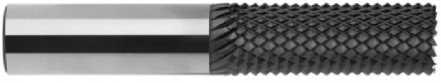
Fig. 1. End mill form SECO [5]
Such contradictory information demands an additional study of influence of the mentioned above angle on machined surface roughness. This investigation may be a base of further tools improvement if their construction is changed. The method used by authors is based on numerical calculation. Now, popular finite element method (FEM) is very often used to calculate homogeneous and heterogeneous work piece cutting processes.
In general, two large groups of such calculations may be distinguished, i.e. macro-modelling and micro-modelling [17–19]. Micro-modelling includes fiber, matrix and interfacial layer (fiber-matrix interface) description. Previously the authors of the presented paper used FEA to calculate strain-stress in UD-FRC cutting zone [20]. Micro-model simulation was executed as 3D task with fibers, matrix and interfacial layers. However, obtained results did not conform to experiment pictures perfectly.
There are many publications with positive examples of cutting zone modeling using smooth particle hydrodynamics method (SPH). However, these examples refer to homogeneous material cutting only [21–23].
For this reason, an attempt of micro-modeling of UD-FRC cutting zone is made with the use of SPH method. The main goal of the research is an estimation of new cutting wedge geometry to decrease fibers-matrix interfacial debonding. The practical result should be a new tool design for UD-FRC work- pieces processing.
-
2. Problem statement and assumptions
-
3. Calculation results
Cutting simulation is executed with SPH software un i t of computer program ABAQUS. Steel fibers at 25–450 °C and strain rate equal up to 600 c –1 have the foll o wing parameters: the yield stress a = 1 150 MPa, the strain-hardening constant b = 739 MPa, the strain rate constant с = 0,014, the work hardening exponent n = 0,26, the thermal softening exponent m = 1, 0 3, m elting temperature T m = 1723 K [24, 25]. Matrix material has a = 352 MPa, b = 440 MPa, c = 0,0083, n = 0,42, m = 1, T m = 520 K. Frictional coefficient is equal to 0,3 everywhere [26].
The model source data are: three-dimensional approach; free orthogonal and oblique cutting of composite workpiece. Parallelepiped workpiece has sizes 0,112 × 0,08 × 0,045 mm. A tool is represented as a wedge with parameters: rounded cutting edge radius ρ = 0,001 mm, tool orthogonal rake γ = 15°, tool orthogonal clearance α = 7° and tool cutting edge inclination λ = 45°. Cutting speed vector is directed along workpiece axis; cutting speed Vc = 0,15 m/s; cutting depth t = 0,01 mm. Composite fibers are located at an angle to the horizon equal to ψ = 90°. Fiber diameter equals to 0,014 mm, distance between fiber axes equals to 0,018 mm.
The composite has the following properties. Fibers are made of structural alloy steel STEEL 4340 (Russian analogy – 40XH2MA) and have the such properties: density 7800 kg/m3, Young’s modulus E = 210 GPa, fracture strain 0,95. Matrix material is aluminum alloy AL6061-T6 (Russian analogy – AD33) with the density 2700 kg/m3 [16]. The fiber and matrix material behavior model is Johnson-Cook hardening model. Workpiece is completely fixed by its lower edge (Fig. 2).
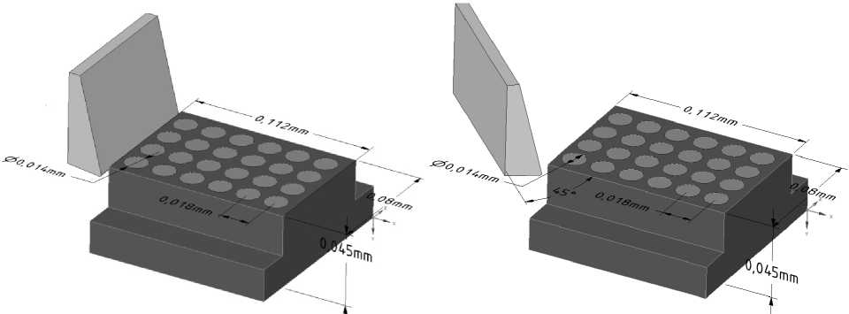
Fig. 2. Theoretical model (orthogonal cutting – on the left, oblique one – on the right)
Calculation results for orthogonal and oblique cutti n g are shown in Fig. 3 a nd 4. One can see that oblique cutting has minimal fibers bend in the cutting speed vector direction. Accordingly, fibers-matrix debonding is less in this case. Thus it can be confirmed that the usage of tools w ith large cutting edge inclination in UD-FRC machining is reasonable.
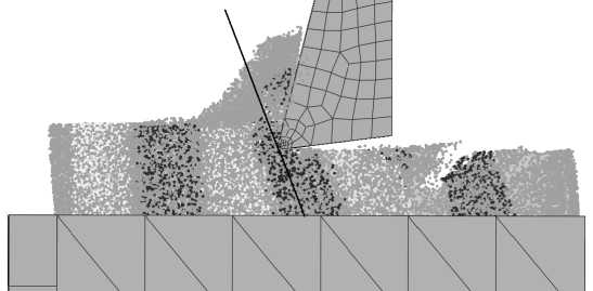
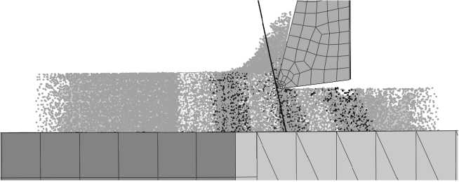
Fig. 3. Orthogonal (above) and oblique (below, turned around vertical axis) cutting. Image is located at right angle to tool major cutting edge
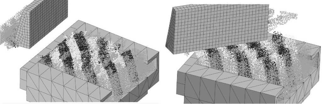
Fig. 4. Orthogonal cutting (on the left) and oblique one (on the right). Isometric view
Since maximal fiber and matrix deformations are o b served in normal to m a jor cutting e dge direction, so is reasonable to decrease such deformations. One of the ways to obtain it is to use the opposite cutting process by symmetrically located wedge. Furt h ermore, to exclude undesired excessive chip packing in a zone between the adjacent cutting edges the last one should be shifted behind the first one.
It gives the possibilities to remove chip between wedges on the one hand, and to o r ganize opp o site fiber and matrix motion in front of the cutting edge on the other hand. Considering the fact that t h e cutting speed is very high, material inertia in cutting zone may pr e serve its deformation a f ter the first tooth action to opposite influence from the second one. Such cascading effect from interleaved teeth gives fiber deformation decrease and fiber-matrix debonding reduction.
This cutting mode is also calculated, deformation images are shown in the Fi g . 5. It turne d out that deformation in front of the second tooth is less than defor m ation in front of single one. Undesir e d excessive chip packing in a zone between the adjacent cutting edges is not observed. On this basis a new milling cutter design with tool major cutting edges located as a chevron on a cylindri c al surface with alternate arrangement is suggested. As one can see in the Fig. 6, in contrast to the p r ototype, tool cutting edge angle equals to 90°. This milling cutter should be manufactured by prelimina r y cutting-out of helix flutes in opposite directions. The perfect orthogonal rakes should be provided in this case. Further, major flanks should be grinded.
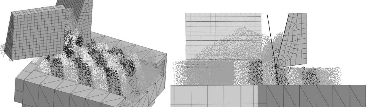
Fig. 5. Oblique cutting. Two opposite located wedges
Fig. 6. Milling cutter with rectangular shape tooth in the tool reference plane (to compare, milling cutter from SECO on the right side)
-
4. Conclusions
-
1. Unidirectional fiber-reinforced composite workpie c e surface quality improvement is obtainable in the case of fiber and matrix deformation decreasing by using oblique cutting and opposite alternate arrangement of major cutting edges.
-
2. Alternate arrangement of major cutting edges excludes undesired excessive chip packing in a zone between the adjacent cutting edges. Material inertia in cutting zone can preserve its deformation after the first tooth to opposite influence from the second one. Such cascading e f fect from i n terleaved teeth gives fiber deformation decrease and fiber-matrix debonding reduction.
-
3. SPH method is sufficient for micro-modeling of U D -FRC workpiece cutting process.
-
5. Discussion and application
Although studies have established qualitative assessment of composite fiber bending, it is essential to calculate fiber-matrix interface damage length along fiber orientation. The usage of SPH method has not given appropriate values of these characteristics. It is necessary to crowd particles set and to increase model size, that nowadays is limited by computer possibilities (simulation is executed by computer with Core i7-4790k with 8 threads processor during several hours).
Considering the fact that this simulation is not verified by experiment yet, the adequacy of obtained results is not sufficient. The distance between opposite adjacent cutting edges should be calculated more precisely. This distance depends on composite properties as well as on cutting parameters. Moreover, a question about overlapping of tool major cutting edges should be resolved. So, the results of proposed investigation should be admitted as preliminary results.
References Fiber-reinforced composite workpiece surface quality improvement in machining by milling-cutter with opposite cutting edges using SPH-method simulation
- Sheikh-Ahmad J.Y. Machining of polymer composites. Springer, 2009. 315 p. DOI: DOI: 10.1007/978-0-387-68619-6
- Teti R. Machining of Composite Materials. CIRP Annals -Manufacturing Technology, 2002, vol. 1, iss. 51, no. 2, pp. 611-634. DOI: DOI: 10.1016/S0007-8506(07)61703-X
- Machining carbon fibre materials. User guide. Sandvik Coromant., 2010. 63 p.
- Composite Machining Guide. Kennametal., 2012. 22 p.
- JABRO -Composite machining. SECO, 2011. 40 p.
- Tooling for Composites and Aerospace Materials. Guhring., 2011. 4 p.
- Patil A.A., Shende M.D. Experimental and Analytical Investigation of Drilling of Sandwich Composites: A Review. IOSR Journal of Mechanical and Civil Engineering, 2013, vol. 6, iss. 6, pp. 40-52. DOI: DOI: 10.9790/1684-0664052
- Kahwasha F., Shyhaa I., Maheri A. Modelling of cutting fibrous composite materials current practice. Procedia CIRP, 2015, no. 28, pp. 52-57. DOI: DOI: 10.1016/j.procir.2015.04.010
- Schorník V., Dana M., Zetková I. The Influence of the Cutting Conditions on the Machined Surface Quality when the CFRP is Machine. Procedia Engineering, 2015, no. 100, pp. 1270-1276. DOI: DOI: 10.1016/j.proeng.2015.01.493
- Naresh N., Rajasekhar K., Vijaya Bhaskara Reddy P. Parametric analysis of GFRP composites in CNC milling machine using Taguchi method. IOSR Journal of Mechanical and Civil Engineering, 2013, vol. 6, no. 1, pp. 102-111. DOI: DOI: 10.6084/m9.figshare.1051567
- Mkaddem A., Mansori M.E. Finite element analysis when machining UGF-reinforced PMCs plates: Chip formation, crack propagation and induced-damage. Materials and Design, 2009, vol. 30, pp. 3295-3302 DOI: 10.1016/j.matdes.2008.12.009
- Zhou L., Huang S.T., Wang D., Yu X.L. Finite element and experimental studies of the cutting process of SiCp/Al composites with PCD tools. International Journal of Advanced Manufacturing Technology, 2011, vol. 52, pp. 619-626 DOI: 10.1007/s00170-010-2776-2
- Soldani X., Santiuste C., Muñoz-Sánchez A., Miguélez M.H. Influence of tool geometry and numerical parameters when modeling orthogonal cutting of LFRP composites. Composites: Part A, 2011, vol. 42, pp. 1205-1216 DOI: 10.1016/j.compositesa.2011.04.023
- Mkaddem A., Demirci I., Mansori M. A micro-macro combined approach using FEM for modelling of machining of FRP composites: Cutting forces analysis. Composites Science and Technology, 2008, vol. 68, pp. 3123-3127 DOI: 10.1016/j.compscitech.2008.07.009
- Dandekar C.R. Multi-step 3-D finite element modeling of subsurface damage in machining particulate reinforced metal matrix composites. Composites: Part A, 2009, vol. 40, pp. 1231-1239 DOI: 10.1115/1.2164508
- Raoa G.V.G., Mahajana P., Bhatnagarb N. Three-dimensional macro-mechanical finite element model for machining of unidirectional-fiber reinforced polymer composites. Materials Science and Engineering, 2008, vol. 498, pp. 142-149 DOI: 10.1016/j.msea.2007.11.157
- Raoa G.V.G., Mahajan P., Bhatnagar N. Micro-mechanical modeling of machining of FRP composites -Cutting force analysis. Composites Science and Technology, 2007, vol. 46, pp. 579-593 DOI: 10.1016/j.compscitech.2006.08.010
- Raoa G.V.G., Mahajan P., Bhatnagar N. Machining of UD-GFRP composites chip for-mation mechanism. Composites Science and Technology, 2007, vol. 67, pp. 2271-2281 DOI: 10.1016/j.compscitech.2007.01.025
- Usui S., Wadel J., Marusich T. Finite Element Modeling of Carbon Fiber Composite Orthogonal Cutting and Drilling. Procedia CIRP, 2014, vol. 14, pp. 211-216 DOI: 10.1016/j.procir.2014.03.081
- Щуров, И.А. Моделирование процесса резания заготовок из композитных материалов с применением метода конечных элементов/И.А. Щуров, И.С. Болдырев//Вестник ЮУрГУ. Серия: Машиностроение. -2012. -№ 12 (271). -Вып. 19. -С. 143-147.
- Limido J., Espinosa C., Salaün M., Mabru C., Chieragatti R. High speed machining modelling: SPH method capabilities. 4th Smoothed Particle Hydrodynamics European Research Interest Community (SPHERIC) workshop, 2006.
- Limido J., Espinosa C., Salaün M., Lacome J.L. SPH method applied to high speed cutting modeling. International Journal of Mechanical Sciences, 2007, vol. 49, iss. 7, pp. 898-908 DOI: 10.1016/j.ijmecsci.2006.11.005
- Bagci E. 3-D numerical analysis of orthogonal cutting process via mesh-free method. International Journal of the Physical Sciences, 2011, vol. 6, pp. 1267-1282 DOI: 10.5897/IJPS10.600
- Johnson G.R., Cook W.H. Fracture characteristics of three metals subjected to various strains, strain rates, temperatures and pressures. Engineering Fracture Mechanics, 1985, vol. 21, no. 1, pp. 31-48 DOI: 10.1016/0013-7944(85)90052-9
- Gray III G.T., Chen S.R., Wright W., Lopez M.F. Constitutive Equations for Metals Under Compression at High Strain Rates and High Temperatures. LA-12669-MS, IS-4 Report section. USA, Los Alamos National Laboratory, 1994. 62 p.
- Arola D., Ramulu M. Orthogonal cutting of fiber-reinforced composites: a finite element analysis. International Journal of Mechanical Sciences, 1997, vol. 39, no. 5, pp. 597-613 DOI: 10.1016/S0020-7403(96)00061-6
