First Principles Investigation of Electronic and Electrical Properties of Carbon Nanotube Interfaces

Author: Latypov Ruslan Maratovich, Sergey Anatolevich Sozykin, Valeriy Petrovich Beskachko
Section: Физика
Article in issue: 4 т.17, 2025.
Free access
In the last two decades, researchers have been studying various interaction issues between electrodes (primarily metals) and single-wall carbon nanotubes (SWCNTs), including contact resistance. To create electronic devices and electrical circuits based on SWCNTs, it is crucial to have a better understanding of how the interface between the electrode and the nanotube influences contact resistance. The electronic and electrical characteristics of SWCNT (6,6) in contact with other SWCNTs were investigated using density functional theory (DFT) and non-equilibrium Green's function (NEGF) methods using the SIESTA software package. We explored the rotation of SWCNTs relative to electrodes and obtained dependences of resistance, band structures, and local density of states (LDOS) for SWCNT models as a function of rotation angle. In cases where the electrodes and central tube were identical, a three-fold decrease in conductance was observed at 12 degrees. The resistance behavior was due to the localization of electrons near the interface, as confirmed by the LDOS analysis. When the electrodes and central tube were different, the calculated resistances were very high, making these interface configurations ineffective for circuit applications.
Carbon nanotubes, DFT, NEGF, electrical resistance, band structure, local density of states
Short address: https://sciup.org/147252300
IDR: 147252300 | UDC: 538.9 | DOI: 10.14529/mmph250412
Первопринципное исследование электронных и электрических свойств интерфейсов углеродных нанотрубок
За последние два десятилетия были изучены различные аспекты взаимодействия между электродами (в основном металлическими) и одностенными углеродными нанотрубками (ОУНТ), включая контактное сопротивление. Интерес к этой тематике связан с тем, что для создания электронных устройств и электрических схем на основе ОУНТ необходимо понимать, как конфигурация контакта между электродом и нанотрубкой влияет на контактное сопротивление. В настоящей работе электронные и электрические свойства ОУНТ (6,6) при контакте с другими нанотрубками были исследованы с помощью теории функционала плотности и метода неравновесных функций Грина с использованием программного пакета SIESTA. В частности, были получены зависимости сопротивления, зонной структуры и локальной плотности электронных состояний (LDOS) моделей ОУНТ от угла поворота нанотрубки относительно электродов. В случае, когда электроды и центральная нанотрубка были одинаковыми, наблюдалось уменьшение проводимости в три раза при угле 12°. Изменение сопротивления было вызвано локализацией электронов вблизи контакта, что подтверждается анализом LDOS. В случае, когда электроды и центральная нанотрубка были разными, расчетные сопротивления были очень высокими, поэтому такие конфигурации интерфейса неэффективны для использования в электрических схемах.
Text of the scientific article First Principles Investigation of Electronic and Electrical Properties of Carbon Nanotube Interfaces
Carbon nanotubes (CNT) remain a promising material for nanoscale field effect transistors (FET) [1]. It is possible to fabricate CNT FET with a gate length of 5 nm [2], minimizing a transistor footprint down 40 nm [3]. Excellent mechanical and electrical properties make CNT utilizable in printed film flexible electronics [4]. CNT FET massive production is possible, but it requires to solve technological difficulties [5]. The main problems are correlated with the metrology and quality control [5]. Also, the industry lacks a general experience and know-how on CNT FET mass fabrication [5]. On laboratory scale, it is possible to fabricate a RISC-V microprocessor from CNT FETs [6]. Besides FETs, CNT has a great potential in gas sensing [7]. C 2 H 2 and H 2 molecules can be detected via a simple electrical response [8]. Furthermore, the reaction to magnetic field makes CNTs a promising material for spintronics [9]. In general, CNT have applications in many fields, various prototypes were constructed, but a commercial production has not yet been achieved.
The interaction of metals with single-walled carbon nanotubes has been one of the most actively studied areas over the past twenty years. Among the most important contact parameters are the height of the Schottky barrier [10, 11] and contact resistance [12, 13] which are defining parameters for CNT FETs. It is well established, that these parameters depend on interface type and electrode material [10– 13]. Yet, the exact dependence is a subject for further investigations. This is required to produce CNT FETs and gas sensors with predetermined parameters. Single-walled carbon nanotubes (SWNT) structure defects also influence its resistance besides electrode material [14–16]. Even with related structure, SWNT-graphene interface can exhibit diverse properties [17, 18]. Understanding contact resistance behavior in case of nanotubes with an unideal interface can help to engineer electric circuits based on SWNT. Density functional theory calculations enable investigation of the precise interface geometry and electrode material [10–13] without additional factors, in comparison with experiment.
In this paper, we investigated SWNT–SWNT interface properties by first-principles calculation methods. We calculated interface dependence of SWNT resistance, band structures and local density of states. We found out interface configuration when SWNT resistance is increasing by three times of pristine one. In some cases, the local density of states shifts to contact sites, leaving empty cross rings of SWNT.
Current-voltage characteristics of ideal SWNT (6,6) were calculated using the software package SIESTA [19], based on the density functional theory and nonequilibrium Green’s function method with double-ξ (DZ) basis sets [20]. Relaxation of the carbon nanotube’s geometry was performed based on the local density approximation (LDA) and the generalized gradient approximation (GGA) with Ceperley–Alder (CA) and Becke–Lee–Yang–Parr (BLYP) pseudopotentials, respectively. The mesh cutoff was 200 Ry. The k -point distribution for all structures was 1×1×30 in x -, y - and z -directions (tube axis), respectively. GUI4dft was used to analyze the calculation’s output [21].
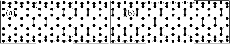
Relaxed SWNT geometries, consisting of 72 and 96 atoms, were used to construct simulation models with the central region through which current is driven in response to a voltage applied to the left and the right regions which are treated as electrodes. The distance between the central region and electrodes from both sides was taken as the average distance between circles of the nanotube: 1,231 Å and 1,242 Å for LDA and GGA, respectively. The structure was oriented in such way, that the tube is parallel to the z-direction. There were 4 models in total, which are called “72–72”, “72–96”, “96–72” and “96–96”, where the first number is the quantity of atoms in each electrode regions, the second one is the number of atoms in the central region. Some of the models are presented in fig. 1, a and b .
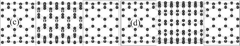
For angular dependence of SWNT resistance calculation we used LDA, the central region of “72– 96” model rotated around the axis of the tube. The third number in the designation of such models is the angle (in degrees) of the central region rotation relative to the electrode regions. The structures of the “72–96–4” and “72–96–14” models are shown in fig. 1, c and d , respectively. TBtrans was used for current’s calculation of electrode systems [20].
Electrode systems calculations with different from central tube electrodes were also performed in LDA approximation. The distance between electrodes remains 1,231 Å. Such models were named according to the chiral indices of the electrodes and the central part. For example, (4,4)(6,6)(4,4), where the first and last brackets mean chiral indices of electrodes SWNT and the middle one of the central tube.
Electrode Central region Electrode Electrode Central region Electrode
Electrode Central region Electrode Electrode Central region Electrode
Fig. 1. The SWNT with electrodes: (a) “72–72”; (b) “72–96”; (c) “72–96–4”; (d) “72–96–14”
Result and discussion
|
SWNT (6,6) is an armchair nanotube with a resistance 6450 ohm (theoretical calculations) [22]. The calculated resistances from the linear I–V curves of various models are presented in Table 1. GGA have a smaller error than LDA, but both errors (relative to 6450 ohm) are less 0,5 %. LDA approximation has a less computational cost and faster mesh cutoff convergence than GGA [23], so we used it in the following calculations. The “72– |
Table 1 The resistance of SWNT (6,6) in various models |
|||
|
Model |
Approximation |
Resistance, Ω |
Error, % |
|
|
“72–72” |
LDA |
6461 |
0,17 |
|
|
“72–96” |
LDA |
6476 |
0,41 |
|
|
“96–72” |
LDA |
6482 |
0,51 |
|
|
“96–96” |
LDA |
6474 |
0,38 |
|
|
“72–72” |
GGA |
6464 |
0,22 |
|
|
“72–96” |
GGA |
6469 |
0,30 |
|
|
“96–72” |
GGA |
6458 |
0,13 |
|
|
“96–96” |
GGA |
6459 |
0,15 |
|
96” model was used as the basis for the rotated structures.
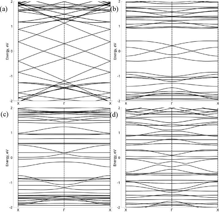
Fig. 2. The band structures of (a) “72–96”; (b) “72–96–8”; (c) “72–96–12” and (d) “72–96–18” models. Energies have been shifted to Fermi level
The band structures of electrode systems with the pristine and rotated central region are presented in fig. 2. The bending of bands around the Fermi level is observed (fig. 2, b ) and further bending of more bands at higher angles. The gap in valence bands is observed at 8° angle, at higher angles it disappeared.
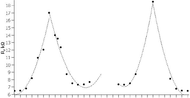
The I–V curves of rotated structures were also linear and consisted of three points: 0, 0,2 and 0,4 V. The angular dependence of SWNT resistance is shown in fig. 3. Change of curve periodicity each 12° is observed. We note the geometry periodicity of SWNT (6,6) is 60°. It means rotation angles, for example, 4° and 56° (60°–4°) are equivalent. Resistances of structures with equivalent angles are the same except for 12° and 48° angles with 8 % difference. It can be explained by the instability of this structure, the uneven distribution of C-C bonds at contact sites.
0 2 4 6 8 1012 1416 18 20 22 24 26 28 30 32 34 36 38 40 42 44 46 48 50 52 54 56 58 60
Angle of rotation, -
Fig. 3. Angular dependence of SWNT resistance.
Parabolic approximations are shown by dashed lines
Latypov R.M., Sozykin S.A., Beskachko V.P.
The local densities of states with the pristine and rotated central tube are presented in fig. 4. They were calculated in the energy range from EF – 0,1 eV to EF with iso surface value 10–4 states . It shows an electron’s transition to junctions of the central and the electrode regions at high angles, which we can see in fig. 4, d. In case of 12° angle (fig. 4, c) almost empty rings in the central tube are observed. It can explain high resistance of this case.
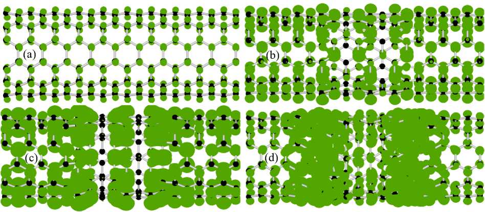
Fig. 4. The local density of states of: (a) “72–96”; (b) “72–96–8”; (c) “72–96–12”; (d) “72–96–18” models
Electrode system resistances with different types of electrodes: armchair SWNTs with (4,4), (5,5), (7,7) and (8,8) chiral indices are presented in table 2. The central tube remained the same SWNT (6,6). The higher a difference in chiral indices between electrodes and the central tube, the higher a contact resistance. We note the contact resistance of SWNT with smaller chiral indices than the central tube is higher than with bigger ones.
Table 2 Resistance of electrode systems with different electrodes. d r – relative difference of central region and electrodes nanotube radius
|
Electrode system |
R, Ω |
d r |
|
(4,4)(6,6)(4,4) |
473934 |
0,33 |
|
(5,5)(6,6)(5,5) |
42371 |
0,17 |
|
(7,7)(6,6)(7,7) |
19546 |
0,17 |
|
(8,8)(6,6)(8,8) |
29134 |
0,33 |
Conclusion
Using density-functional theory and nonequilibrium Green’s function methods, we calculated SWNT – SWNT interface properties. In particular, we obtained the band structures, the local density of states and resistance for various interface configurations. We found out the increase of resistance up to three times the intrinsic one of the armchair SWNT due to rotating the central region. Obtained angular dependence of SWNT resistance can be used for engineering nanomechanical devices. Overall, using armchair SWNT as an interconnector between other armchair SWNTs is probably ineffective in terms of contact resistance, even in the situation, when armchair tubes are the same. However, a careful study of the optimal contact geometry of different chiral SWNTs is needed to ensure this statement.
