Flexible Self-Managing Pipe-line Framework Reducing Development Risk to Improve Software Quality

Author: Nitin Deepak, Shishir Kumar
Journal: International Journal of Information Technology and Computer Science(IJITCS) @ijitcs
Article in issue: 7 Vol. 7, 2015.
Free access
Risk identification and assessment in today’s sce-nario play a vital role in any software/web application devel-opment industry. Many process models deliver the process related to development life cycle, but the risk assessment at an early stage is still an issue and is a significant subject for research. In this paper, an approach based on MVC architecture by embedding spiral process, which is verified and validated by V-shape model is proposed. By using this approach development efficiency will increase due to less burdened working team(s), reduces stressful maintenance effort that causes reduction in risk factors because of beautifully distributed human effort to improve software quality. Besides, the efficiency of our approach is manifested by the preliminary experiment.
Risk, Software Risk, Software Risk Manage-ment, Software Quality, Software Process Model, Process Models, Design Pattern
Short address: https://sciup.org/15012321
IDR: 15012321
Text of the scientific article Flexible Self-Managing Pipe-line Framework Reducing Development Risk to Improve Software Quality
Published Online June 2015 in MECS
This paper starts with the introduction towards risk and risk management and continues with some process models sharing their merits and de-merits, then from these process models it is intimated why specific few process models were taken for the proposed framework introducing the architecture or discipline steps during SDLC of planning of software development to reduce risk and improve software quality and all evidenced via preliminary experimentation and analysis.
To improve the software quality one must reduce risk factors at various stages, which can be measured via various parameters. Many studies and implementations are keen to work on improving quality to reduce risk, some proven ones that are being used (brief given ahead) in our framework.
This paper introduces the theoretical process model for disciplined architecture of software development maturity to improve the team efficiency on individual (team member(s)) specialization, which also ease the tedious maintenance work and reduces risk at early development phase, thus improves software quality at par.
-
A. Risk
All activities in any organization or group entail some uncertainties. Due to internal or external factors that produces an uncertain environment while achieving their objectives and these uncertainties impact on the organization’s objectives certainly is Risk .
-
B. Risk Management
AS/NZS ISO 31000:2009 introduces some principles of risk management [1]:
-
• Build and defend ethics.
-
• Should be the fundamental element of the whole development process.
-
• Should be an integral part of decision making.
-
• Precisely demonstrate potential uncertainties.
-
• Should be organized, configured and on-time.
-
• Should be in shape.
-
• Should consider human values and culture.
-
• Should involve and transparent between individuals to any level of communication.
-
• Should be open, iterative and dynamic to any change.
-
• Should be the part of continuous improvement process.
Almost every enterprise/ organization should work on a framework of Risk Management endlessly [1].
And to identify the risk efficiently one need to segregate the objective into three categories [1]:
-
• Objective Related to Strategy : Comes under the supervision of senior executives within an organization, which are responsible for providing strategic decisions.
-
• Objective Related to Operations : Comes under the middle level managers of an organization those are responsible for aligning the strategic objectives.
-
• Line Objective : These are the actual line manager who comes into action in the development of prod-uct/ software.
-
C. Process Model
Software process life cycle model is either a descriptive or prescriptive characterization of how software is or should be developed. A descriptive model describes the history of how a particular software system was developed. A prescriptive model prescribes how a new software system should be developed.
Standards should be general to different types of soft-ware(s) having differences to the situations or requirements.
These general standards also termed as models or named process models to move ahead on the project efficiently and effectively. Any impasse is not in the show due to prior chosen process model as per the requirement, size or category of the project.
There are various process models like [2]: waterfall model, iterative model, incremental model, prototyping model, spiral model, V-shaped Model etc. with due discipline it enhances the capacity and capability of team.
-
• Waterfall Model
A chronological development approach which emphasizes the flow towards the downwards direction through the phases of requirement analysis → design → implementation → integration → and maintenance.
This model [Fig.1.] accentuates planning at early phases and also anticipates not incorporating any changes in-between. Design is like flowing water in a downward direction so no chance of moving backward or upward.
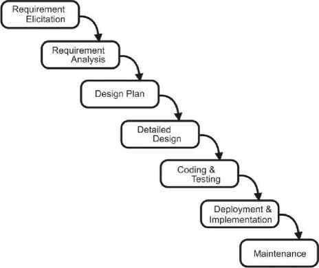
Fig. 1. Waterfall Model
Steps included in the waterfall model detailed below:
-
1) . Requirement & Analysis: Establishing the expectations for software and its functionality. Also analysis to be done for hidden, missed or incomplete requirement to make all specific and documented for further development & understanding, which should be un-doubtful at all levels.
-
2) . Design: Framework should be the outcome of this stage/ phase, which defines the external interfaces and
tools used in the project, can be determined by the designer.
-
3) . Detailed Design: Analysis on design defined earlier and assesses the software components to be developed and prepare a specification for how each component is implemented.
-
4) . Coding & Testing: Implements the detailed design specification and determines whether the software meets the specified requirements and finds any errors present in the code.
-
5) . Deployment & Implementation: After surviving in all testing phases and levels software is deployed at client sites and instructs them to use as per requirement and finally implemented.
-
6) . Maintenance: Modifications & enhancement is now the motive whenever required to make software more robust and efficient.
It has some merits, i.e. reinforces better discipline: define before design, design before code etc. and works well on matured products and in weak teams.
Some de-merits, i.e. unrealistic to expect entire requirements very early in the project, difficult to integrate risk management, difficult to make changes to documents, “swimming up streams” .
-
• Iterative Waterfall Model
The problems with the waterfall model, initiate the demand of new methods of developing systems, which is more flexible than the traditional waterfall model. In Iterative waterfall model development, the project can be developed in parts that results faster development and product can be seen earlier and as per the feedback the process can be repeated in newer versions [Fig.2.].
This modified version has the most attractive aspect is that it enables the phases to overlap when needed, unlike in a pure waterfall model where no overlapping was allowed.
It also has some benefits like the work well with mature products and in weak teams and one more advantage is that it allows overlapping unlike the pure waterfall model .
But still some de-merits as like no scope of the changing requirement, no customization and above all no risk management to improve quality.
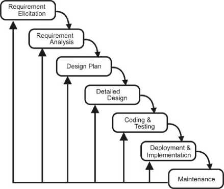
Fig. 2. Iterative Waterfall Model
-
• Incremental Process Model
As the name suggests, incremental means builds are on an incremental basis and evolution of software comes with an every incremental build with some enhancement and modification as required [Fig.3.].
In this model requirements were set of priorities and develop the system in groups. Each release has some added on features than previous ones until all the components have been implemented [17].
It also has some benefits like: generates working software quickly, more flexible, easier to test and debug because of less code/ modules at a time etc.
Very experienced team is needed for planning & design, the cost is high, involves rigidity in each phase of an iteration and change in requirement is almost not possible etc are some drawbacks of this process model.
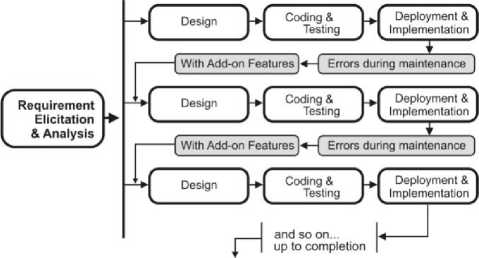
Fig. 3. Incremental Process Model
-
• Prototyping Process Model
Instead of cementing a requirement at early phase before design or implementation, this prototyping process model gives the opportunity to understand the requirement completely.
A prototype is a dummy implementation to understand the proposed system easily and client is also involved easily to make the prototype as good as needed [3].
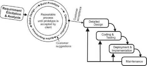
Fig. 4. Prototyping Process Model
The major strength of prototyping is the involvement of the client in developing a prototype model of an actual product, which increases the quality of the product as the generated prototype is much nearer to the actual requirement of the client. Finally, after the acceptance of the prototype the development begins with the iterative process model.
Prototype modeling flavor enhances the capability of iterative process modeling.
-
• Spiral Process Model
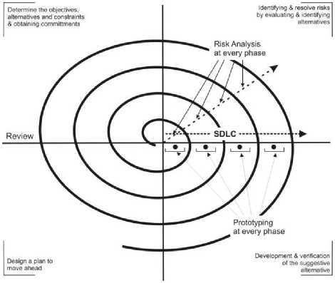
Fig. 5. Spiral Process Model
A process model having radial dimension in shape named spiral model [Fig.5.] enhances SDLC by fusion of risk analysis at every phase in four divisions’ viz.
-
• Determining the objectives, alternatives and constraints and obtaining commitment ,
-
• Identify & resolve risks by evaluating & identifying alternatives,
-
• Development & verification of the suggested alternative, and
-
• Design a plan to move ahead .
These four divisions/ segregation helps in making development easy and risk-considerable at an early stage.
-
• V-shaped Process Model
-
1) . Verification phase of V-Model proceeds with the sequence of
-
a) Requirement analysis: It includes collection of functional & non-functional requirements as per the need of the user .
-
b) Functional specification: It specifies the entire above un-structured requirement collected informal document. And similarly testing team works out the system test plan.
-
c) High-level design: Preparation of abstract design for the solution as per the specified requirement.
-
d) Detailed design/ program specification: All the codes and module design completed along with all codes and algorithms.
-
2) . Validation phase serializes the testing as below:
-
• Unit testing: It tests the detailed design and all the modules individually.
-
• Integration testing: It tests integrated stubs of all the modules as per the high level design structure.
-
• System testing: It tests the whole system as per the functional specification.
-
• User acceptance testing: It entertains the user in testing for acceptance testing.
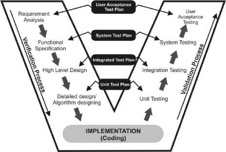
Fig. 6. V-Shape Process Model
It encourages the disciplined software development for sure. It somehow rigid in its process, but easy to use and appreciates whenever requirement completes before design [8]. It works well for small projects.
This model is suggested for large projects on the condition that if follows the approach of CBSE and for every component development one can use V-Model for simplicity, reliability, and re-usability thus improves the quality.
-
II. CBSE
Component based software engineering (CBSE) is based on reusability of software components written in the discipline of software engineering emerged due the unsuccessful object oriented architecture for reusability. Object classes are more detailed than abstraction of components. And abstraction provides a much better opportunity to be reusable, which appreciates COTS for better reusability [6]. Components of-the-Shelf (COTS) base development is much beneficial as reducing cost, less time to develop and market.
CBSE approach reduces development time and it increases quality as it exhibits performance, reliability and usability in comparing to the traditional approach of software development [7].
CBSE approach follows the following steps in software development [7]:
-
a) Identify & choose the prospective components for reusability.
-
b) Assurance for usable components.
-
c) Adjust components as per requirement.
-
d) Assimilate the components to form sub-systems to a new system.
This proven approach can be used in making software development more maintainable and flexible to attach and detach components.
-
III. MVC
Model-View-Controller (MVC) is now the well-known architecture implementing user-interfaces. In 1970’s Smalltalk (a programming language) firstly defined the concept of MVC. From that time onwards the MVC design pattern was becoming routine specifically in object oriented systems [11].
Technology related to re-usability is a common issue among developers and planners. MVC provides component reusability aspect referring sphere definite packages [12].
As is said this system is self-managing, an automatic and it includes some benefits among itself [13]:
-
• Possesses configuration : The system of MVC configures itself with the environment because of its self-configuring behavior.
-
• Possesses robustness : It shields the rest of the system from its flawed activity.
-
• Possesses optimization : Because of having own configuring, own robustness it automatically have its own optimal to proficiently make best use of the possessions to best meet the needs of its ambiance and users.
-
• Possesses protection : It monitors and anticipates the type of attacks like cross-side scripting, unauthorized access, etc. and use appropriate measures to neutralize the attack.
Experiencing different/ traditional architectures for software and web-development, but MVC architecture is an eye opening architecture, which enhances the capacity, fresh-up the mind due to its disciplined framework.
Work Segregation is the best aspect of the MVC framework . As team can be best escorted by making them (Model, View & Controller) separate [13].
-
IV. Perception on Software Quality
Usage of software(s) since 10 years increased radically, especially in communication, to reduce manual intrusion to evaluate better accuracy, to lessen the time consumption etc. usage of software(s) like: E-mail systems (rediff, g-mail, hot-mail), e-ticketing reservation (in railways, airways and now roadways also), e-billing, social media (facebook, we-chat, whatʼs up) etc.
Due to considerable increment in usage of software(s) [15], there is a keen need to maintain & improve software quality. Therefore, emphasis should be made on better process development of software(s), means, needs to retain, maintain & improve software quality on pre-defined attributes like: reliability, modifiability, traceability, portability etc.) .
Software quality needs to be analyzed again & again by researchers and also analyzed many times in the past. After studying various software factors, software quality may be defined as the “combination of understanding & performance of data modeling, creating business logic, designing an innovative layout separately and finally control and monitor the relationship among them by validating and verifying with the specified requirements”.
-
V. Class of Software
Class can be Organic, Semi-detached and embedded as Berry Boehm described in the book title “Software Engineering” .
Organic: miniature range software(s) in this category comes into action, in which experienced developers in this category needed. For e.g., website to any compa-ny/organization etc., web-application, means product line software(s) comes into this category. This type of soft-ware/ application acting as a pillar in the e-information world needs quality to be maintained [17], but, here it is needed to extend the types of projects to 2-50 KLOC to 2-99 KLOC.
Semi-Detached: Mid range software(s) in this category comes into action, in which average previous experience on similar projects is needed. For e.g., utility software(s) like compilers, databases or editors etc. can be developed in this category. Project size could be 50-300 KLOC.
Embedded: This category deals with larger projects, real time systems, complex interfaces. And very little previous experience is needed, but highly specialized types of developers required. For e.g., ATMs, Air Traffic Control etc. be developed in this kind. Project size is normally over 300 KLOC.
This paper emphasizes on organic class of software(s) where up to 2-99 KLOC can be extended. As in this category most of the customized product line packages were developed in this modern world specifically.
-
VI. Purpose of MVC
Major causes due to which this architecture is so efficient are:
-
1) Emphasizes on objects while planning automation rather on irrelevant processes: Firstly, making a story board is easy for any software development project and MVC emphasizes on objects to be mapped conceptually with the user’s and developer’s brain rather focusing on detailed architecture [19].
-
2) Divide ‘n’ Rule: As this says is so popular in negative sense, but positively it encourages the efficiency of the leader to project, direct n monitor the whole task easily and effectively without burdening the team(s).
-
3) Independence: Team members are independent to each other due to the distribution of their independent tasks, which lead towards at higher success ratio.
-
4) Ensuring Responsibility: Disciplined distribution positively emphasizes the individual responsibility.
-
5) Easy Maintenance: Again disciplined distribution & management, maintenance response efficiently and in time services.
Most motivational aspects of MVC are that this pattern is popularly used in web design as an HTML file serves as the model, containing the text to be shown on a webpage, a CSS file contains a description or view of the page’s layout, and the browser serves as the controller, rendering the HTML and CSS data as the webpage viewed [18].
This web design still exists in the modern era technological world. Updating and enhancement incorporates the same pattern efficiently, thus showing low risk architecture stay alive in the latest technology.
This design pattern ensures reduced software risk as of the above causes and thus improves the software quality.
-
VII. Purpose for Spiral Model
Some factors analyzed from literature survey are the fair enough reasons to pick the spiral process model to choose for research:
-
A. Success Ratio is high
Ratio of success is high because of analysis, involvement in depth.
-
B. Overlapped phases
This is also an advantage as because of overlapping of phases means whenever needed team can proceed on and from any phase to modify/ enhance the product at the worst from maintenance phase, in-fact.
-
C. Risk Involvement
The foremost aspect of spiral model is to identify, assessment and resolution of risk factor(s).
-
D. Changes are easy to incorporate
As because of the prototype development of each phase and documentation is disciplined then changes in the same system is easy to incorporate.
-
E. User Involvement
User involvement at every stage for prototyping is one of the best aspects of spiral model. In fact client knows the outcome at the very early stage.
-
F. Flexible
Regular feedback from the user periodically and the changes don’t come as a last minute surprise. Changes are easily accommodated.
-
G. Risk Assessment and Reduction
Risks are assessed and actions are put to reduce the key risks.
-
H. Reusability
If the prototype is operationally useful and robust enough to serve as a low-risk base for future product evolution, then the option of writing specified would be addressed but not exercised.
-
VIII. Proposing a Self-Managing Pipe-Line Framework or Model to Reduce Risk and Improve Software Quality
-
A. Project initiates with requirement elicitation and analysis
Commencement of project comprises the start-up phase of the project. This is the phase where the problem should be defined clearly to what needs to be accomplished and why it’s of great interest to the busi-ness/clients . Most project failures make their root cause in poor or mismanaged expectations of project ventureholders because the project business context was not definite, communicated, and understood by all ventureholders and team members. Therefore, trying to gather and analyze the complete and clear requirements at earliest. And finally document/ specify the whole requirement as SRS.
-
B. Plan the project
Planning of the project doesn’t mean for only schedules and budget, but also involves the effort to be made to successfully complete the project.
The planning phase answers the questions:
-
a. What work must be done to complete the task?
-
b. Feasibility (technical & economical) of the project as per the requirement.
-
c. Distribution planning as per business logic, data modeling and layout processing.
-
d. Who is responsible for the work assigned?
-
e. Deadline of the work done to be decided as per the requirement and budget.
-
f. Risk Assessment & Management Activity.
The planning phase motive is to achieve practical, attainable, schedule, predictable, flexible and communicable development:
-
a. PRACTICAL: capacity of the project should be consistent with resources, capability, time and allocation.
-
b. SCHEDULE: Reasonable time allocations for tasks and proper sequencing of work.
-
c. FLEXIBILITY: Recognition of key risks and contingency plan for managing risk that materializes.
-
g. COMMUNICATION: Definite pathways to communicate between teams, decision making authority and accountability.
-
C. Use-case modeling
User classes and use case diagrams should be prepared to represent the interaction between actors and models for better understanding.
Use case diagrams are used to gather the requirements of a system, including internal and external influences. These requirements are mostly design requirements. So when a system is analyzed to gather its functionalities use cases are prepared and actors are identified [17].
-
D. Activity diagram
An action is the fundamental unit of executable functionality in an activity. An action may have sets of incoming and outgoing activity edges that specify control flow and data flow from and to other nodes. The sequencing of actions is controlled by control edges and object flow edges within activities, which carry control and object events respectively [17] [20].
-
E. Distribution process
This process is to deliver the SRS, use-case model(s) and activity diagram(s) to the respective teams’ viz. business logic team, data modeling team and interaction logic team.
These documentation(s) helps them to proceed further with some facts:
-
1) Fetches the detail for their own specialization.
-
2) Sync with the uniform plan of action.
-
3) Help to develop further specifications.
-
F. The simultaneous derived spiral processes
Database Spiral Process Modeling [Fig.8.] : This derived process model is to develop and produce risk free data modeling having some disciplined steps:
-
i. Prepare some suggestive designs like: External & physical view of database used in the project , and Modeling class and its methods .
-
ii. Verify & validate the above database designs & classes for better alternative as per the documenta-tion(s) provided.
-
iii. Prepare the test-data for testing the proposed database and analyze the risk and try to correct the same or go to step {b} and have another alternative.
-
iv. Develop the final prototype of database for acceptance testing tested by the core team & prepare the final database design to be delivered.
Each of the above phases should revolve sequentially around below aspects:
-
1. Determine the objectives, alternatives and constraints & obtaining commitments in maintain designing database.
-
2. Identifying & resolve risks by evaluating & identifying alternatives.
-
3. Development & verification of the suggestive alternatives.
-
4. Plan for the next phase.
Business Logic Spiral Process Model [Fig.9.]: This derived process model is to identify the controlling class and methods used to control and manage the communication pathway(s) between interaction process & data modeling process efficiently having:
-
i. Prepare some suggestive pathways or methods for controlling the interaction between data-modeling and interaction logic.
-
ii. Verify & validate the suggestive pathways for better alternative as per the documentation(s) provided.
-
iii. Prepare the test-data for testing as per the activity cycle mentioned in activity diagram(s).
-
iv. Develop the final prototype of controlling methods for acceptance testing & finally prepare the final controlling class of business logic design.
Each of the above phases should revolve sequentially around below aspects:
-
1. Determine the objectives, alternatives and constraints & obtaining commitments in controlling the whole scenario.
-
2. Identifying & resolve risks by evaluating & identifying alternatives.
-
3. Development & verification of the suggestive alternatives.
-
5. Plan for the next phase.
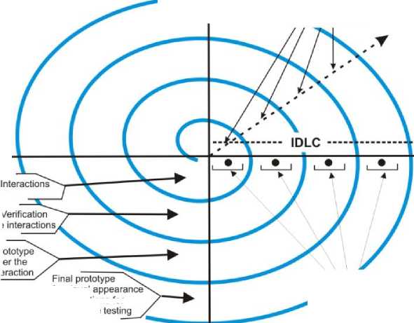
Interaction Spiral Process Model [Fig.10.]: This derived process model is to identify the layout & interactivity platform that deals with the outside world for sincere inputs and maximum required outputs from and to the user by following the below steps:
-
i. Plan and prepare some suggestive layouts and interactions as per the scope of the requirement and user.
-
ii. Verify & validate these above layouts and interactions as per the documentation(s) provided.
-
iii. Prepare the test-data for testing as per the activity cycle mentioned in activity diagram(s).
-
iv. Design & develop the final prototype of layout & interactions for acceptance testing & prepare the final prototype to be implemented.
Each of the above phases should revolve sequentially around below aspects:
-
1. Determine the objectives, alternatives and constraints & obtaining commitments for visual appearances & interactions.
-
2. Identifying & resolve risks by evaluating & identifying alternatives.
-
3. Development & verification of the suggestive alternatives.
-
6. Plan for the next phase.
Verification & Validations phase between data modeling & business logic: In this phase V-shape derived process helps in identifying the correct association between data modeling & business logic by verification and validation (testing). They both moves sequentially as:
Verification Phase-
-
b. Specify all the methods in data modeling class and business logic class.
-
c. Prepare all the state, structured charts and for all the methods and E-R diagrams for the database.
-
d. Convert all the structured charts to detailed algorithms and pseudo code.
-
e. Implement Coding.
Validation Phase-
Develop individual stubs for each level testing viz. unit, integrated & system testing . It flows as below:
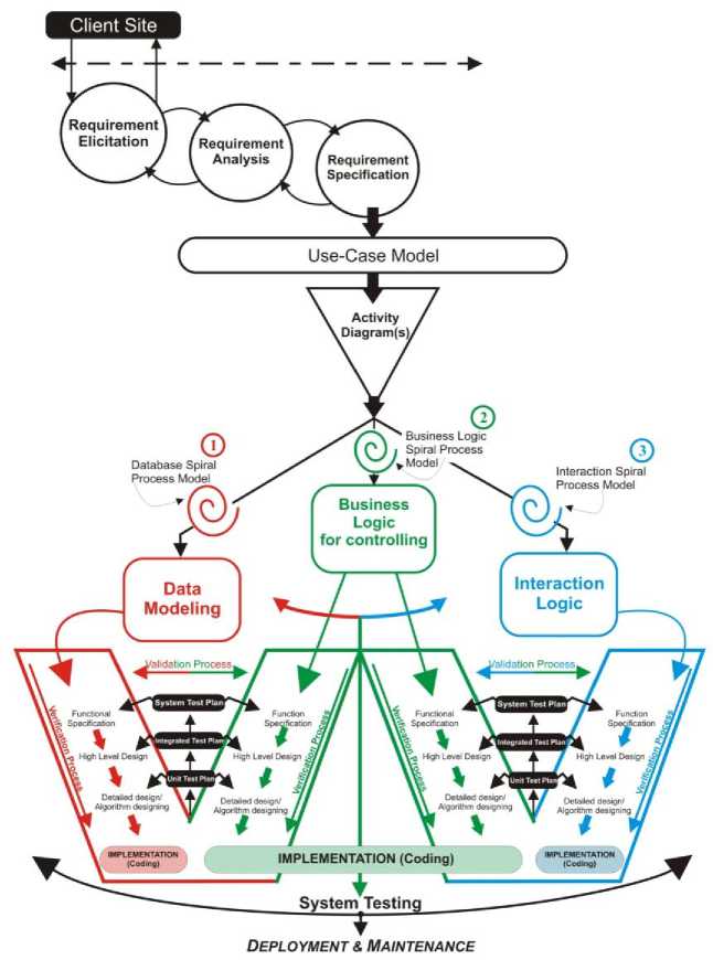
Fig. 7. Self-Managing Pipe-line Framework/ Model
Database designs
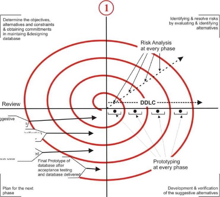
Fig. 8. Database Spiral Process Model
Test the product database by prepare test data / pathways to contra
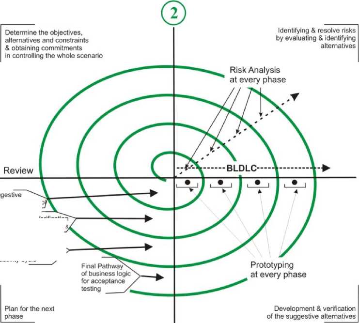
Fig. 9. Business Logic Spiral Process Model
Test the prototype pathway as per the activity cycle
Suggestive
Risk Analysis at every phase
Review
Prototyping at every phase
Fig. 10. Interaction Spiral Process Model
for visual
Plan for the next phase
Table 1. Maintenance Chart
Maintenance Chart
|
Error(s) |
Data Modeling |
Business Logic |
Interaction Logic |
Correction |
|
Unknown data item?? |
√ |
X |
X |
X |
|
File not found!! |
X |
X |
√ |
DONE |
|
Source not included!! |
X |
√ |
X |
DONE |
-
a. Now start with unit testing between the detailed design of data modeling and business logic.
-
b. Then move with integrated testing between the high level design of data modeling and business logic.
-
c. Finally, system testing between the functional specification of data modeling and business logic.
Verification & Validation phase between business logic & Interaction logic: In this phase another V-shape derived process helps in identifying the correct association between business logic & interaction logic by verification and validation (testing). They both move sequentially as:
Verification Phase-
-
a. Specify all the methods in business logic class & interaction layouts methods.
-
b. Prepare all the state, structured charts and for all the methods in business logic and layouts methods.
-
c. Convert all the structured charts to detailed algorithms and pseudo code.
Validation Phase-
Develop individual stubs for each level testing viz. unit, integrated & system testing . It flows as below:
-
a. Now start with unit testing between the detailed design of business logic and interaction design.
-
b. Then move with integrated testing between the high level design of business logic & interaction design.
-
c. Finally, system testing between the functional specification of business logic design and interaction design.
-
G. System testing plan after the development and assembling the whole project
Business logic/ controlling team will ensure the error correction/ maintenance, distribution by labeling in the tabular format, access to all the teams [Table 1].
This framework beautifully segregated the design approach to reduce risk, thus improves the software quality. Maintenance chart positively enhances the capability of either team as less and specialized work. Finally the tabular format of the maintenance chart always helps in decision making for the betterment of software quality.
After experimenting with developing web-application using proposed approach and comparing it with the traditional approach , four factors have been analyzed i.e. effort, team performance, congestion, and requirement accommodation. Here, the web application used is to add & update faculty, news and events on the institute website to display effectively on web within time as when required.
Team A
Task to be performed by
[Member 1]
Add Faculty
Plan Input design
Plan Validation
Plan Logic to insert in database
Plan Output design
[Member 3]
Add News/Events
Plan Input design
Plan Validation
Plan Logic to insert in database
Plan Output design
[Member 2]
Modify Faculty
Plan Input design
Plan Validation
Plan Logic to update in database
Plan Output design
[Member 4]
Modify News/Events
Plan Input design
Plan Validation
Plan Logic to update in database
Plan Output design
Fig. 11. Showing distribution of tasks in Team A with traditional approach
Here [Table 2] displays the nature of operations performed at a time by a member of a team. For e.g. Member 1 of Team A has to plan for ‘Add_Faculty’ module, then he/ she has to perform 4 different natured operations viz. ‘plan input design’, ‘plan validations’, ‘plan database processing’ and finally ‘plan for output design’. And so on for every member.
Team В
Task to be performed by
[Member 1]
Input/ Output Design for
Add_Faculty
ModifyFaculty
Add News/ Events
Modifying News/ Events
[Member 3]
Database processing logic for
Add_Faculty
Modify_Faculty
Add News/Events
Modifying News/ Events
[Member 2]
Controlling Logic design for
Add_Faculty
Modify_Faculty Add News/Events Modifying News/ Events
[Member 4]
Synchronization between all three for
AddFaculty
Modify_Faculty
Add News/Events
Modifying News/ Events
Fig. 12. Showing distribution of tasks in Team B with the proposed approach
Table 2. Operation performed at a time analyzed from Fig. 11
|
Team A Members |
Module |
Nature of Operations Count |
|
|
Similar |
Different |
||
|
Member 1 |
Add_Faculty |
0 |
4 |
|
Member 2 |
Modify_Faculty |
0 |
4 |
|
Member 3 |
Add News/ Events |
0 |
4 |
|
Member 4 |
Modify News/ Events |
0 |
4 |
Table 3. Operation performed at a time analyzed from Fig. 12
|
Team B Members |
Module |
Nature of Operations Count |
|
|
Similar |
Different |
||
|
Member 1 |
Input/ Output design |
4 |
0 |
|
Member 2 |
Controlling Logic Design |
4 |
0 |
|
Member 3 |
Database processing Logic |
4 |
0 |
|
Member 4 |
Synchronization |
4 |
0 |
But, the [Table 3] displays the nature of operations performed at a time by a member of a team. For e.g. Member 1 of Team B has to plan for ‘In-put/Output_Design’ module, then he/ she has to perform 4 similar operations that is designing an input/ output windows for viz. ʻAdd_Facultyʼ, ʻModifying_Facultyʼ, ʻAdd_News/ Eventsʼ, Modifying_News/ Eventsʼ . And so on for every member.
|
Findings from Table 2 & 3 |
Team A |
Team B |
|
Modules assigned |
4 |
4 |
|
Operations per modules per member |
4 |
4 |
|
Nature of operations per module |
Different |
Same |
|
Nature of Work |
Complex |
Simple |
|
Efficiency per module per member |
25% |
100% |
Efficiency for Team A -
Full Efficiency
No of diff . operations
100 % =25% 4
If the operations per module are same in nature, then a number of different operations is 1. So, the full efficiency per member is distributed is no. of operations:
Efficiency for Team B -
Full Efficiency No of diff . operations
100 %
100%
be same in nature to enhance the performance. vates in using the proposed approach, which dominates the traditional approach.
Table 5. Factors Concluded from Table 4
|
Factors |
Traditional Approach |
Our Approach |
|
Changes in User Requirement |
Complex to accommodate |
Easy to accommodate |
|
Nature of Team |
Dependent |
Independent |
|
Maintenance |
Complex |
Simple and easy |
|
Coding |
Complex |
Simple and easy |
|
Cyclomatic Complexity* |
04 to 08 |
02 to 04 |
Cyclomatic Complexity* increases in [Table 5] of traditional approach as Member(s) of a team has to deal different operations at a time by his/ her own viz.
Modify_News_Events :
Table 6. Overall Cyclomatic Complexity via Traditional approach
|
Task (s) |
Cyclomatic Complexity |
|
Input Designing |
1 |
|
Validation |
4 |
|
Logic to insert in database |
4 |
|
Output Design |
1 |
|
Total |
10 |
On the contrary Cyclomatic Complexity* in [Table 6] decreases in proposed approach as Member(s) of a team has to deal same operations at a time by his/ her own viz.
Database processing logic :
Proposed approach [Fig.7] in this paper decreases cyclomatic complexity and all the operations performed by a member (s) of single category and less test-cases due to declining cyclomatic complexity.
Table 6. Cyclomatic Complexity via proposed approach
|
Task (s) |
Cyclomatic Complexity |
|
Add_Faculty |
1 |
|
Modify_Faculty |
2 |
|
Add_NewsEvents |
1 |
|
Modify_NewsEvents |
2 |
|
Total |
6 |
Finally concluded that the proposed approach in this paper provides a better quality product and this process reduces risk in development strategy, but needed some good experience for distribution and assembling of tasks to decrease some risk and delivered an improved quality product.
* Here cyclomatic complexity means number of test case(s) in test suite(s).
-
X. Advantages Using Proposed Model
The proposed approach [Fig. 7] proposes to reduce software development risk and improvement in software quality. It reduces the technical controversies that emerge during the development phases, resulting enhancement in the power of thinking and specialization.
It displays the framework [Fig. 7] for another very effective process model that can be used to deploy with SDLC for better software quality having low risk towards [15]:
-
1) . User Requirements: Due to the distribution in working tasks, integrated in different requirement windows, for different type of requirements - thus incorporates the same easily to enhance the software. This allocation makes the environment more open, iterative and dynamic to any change [1].
-
2) . Team: Distribution of team for data-modeling , business logic and interaction & appearances motivates team to work in less burdened environment and on single track as specialization. While using this model the team leads should be previously experienced to monitor the whole scenario thus reduces risk in monitoring and development.
-
3) . Maintenance: All separated windows makes maintenance more open, iterative, interactive and dynamic. Separate maintenance team that already dealing as business logic planning who decide the incoming maintenance will go to which team.
So the tabular method [Table 1.1] enhances the capability of maintenance effort that automatically segregates corrective maintenance, enhancement maintenance in their respective windows that automatically drives to the concerned team.
-
4) . Less code: Component architectural and reusability aspect produces less code, which again a big advantage over traditional approaches.
-
5) . Low Cyclomatic complexity structure: Segregated modules ruled cyclomatic complexity at lower side [17].
V (G) =E-N+2 (3)
Where, ‘ E’ refers to the Number of Edges and ‘ N’ refers to Number of Nodes. Here edges mean probabilities and nodes means conditions .
If applying this above formula, proves the low Cyclomatic complexity, structure means minimum testcases that leads to minimum time frame for quality testing, thus reduces technical risk and improves software quality.
-
XI. Conclusion
References Flexible Self-Managing Pipe-line Framework Reducing Development Risk to Improve Software Quality
- AS/NZS ISO 31000:2009, “Risk Management – Principles & Guidelines”, 2009. Standards New Zealand.
- Walt Scacchi, “Process Models in Software Engineering”, Final Version to appear in, J.J. Marciniak (ed.), Encyclo-pedia of Software Engineering, 2nd Edition, John Wiley and Sons, Inc, New York, December 2001
- Seema,, Sona Malhotra, “Analysis and tabular comparison of popular SDLC models”, International Journal of Ad-vances in Computing and information Technology, ISSN 2277-9140
- Barrry W. Boehm, TRW Defence System Group, “A Spiral Model of Software Development and Enhancement”, 1986.
- S.Balaji, Dr.M.Sundararajan Murugaiyan, “Wateerfall vs V-Model Vs Agile: A Comparitive Study on SDLC”, Inter-national Journal of Information Technology and Business Management, ISSN 2304-0777.
- R. Moraes, J. Duraes, R. Barbosa, E. Martins, H. Madeira, “Experimental Risk Assessment and Comparison Using Software Fault Injection”, 37th Annual IEEE/IFIP Interna-tional Conference on Dependable Systems and Networks (DSN'07) 0-7695-2855-4/07 $20.00 © 2007.
- Avraham Leff, James T. Rayfield, “Web-Application De-velopment Using the ModelNiewlController Design Pat-tern”, 0-7695-1345-2, 2001 IEEE.
- Loveleen Kaur & Dr. Hardeep Singh , “Software Compo-nent Selection techniques - A review”, IJCSIT - s, Vol. 5 (3) , 2014, 3739-3742.
- Ishita Verma, “Study of Component Based Software Engi-neering”, IJCSCN. Vol 4(3), 84-88, ISSN:2249-5789.
- Radhika D Amlani, “Advantages and Limitations of Dif-ferent SDLC Models”, IJCAIT, ISSN: 2278-7720.
- http:// poincare.matf.bg.ac.rs/ ~andjelkaz/ pzv/ cas4/ mvc.pdf
- Mahemoff, M.J.; Melbourne Univ., Parkville, Vic., Aus-tralia ; Johnston, L.J., “Handling multiple domain objects with Model-View-Controller”, Technology of Object-Oriented Languages and Systems, 1999. TOOLS 32. Pro-ceedings
- Edward Curry, National University of Ireland, Galway, Paul Grace, Lancaster University, “Flexible Self-Management Using the Model-View-Controller Pattern”, Published by the IEEE Computer Society, 2008.
- Andreas Holzinger, Karl Heinz Struggl, Matjaž Debevc, “Applying Model-View-Controller (MVC) In Design And Development Of Information Systems: An example of smart assistive script breakdown in an e-Business application”, e-Business (ICE-B), Proceedings of the 2010 International Conference.
- Nitin Deepak, Shishir Kumar, “Perceptions on Risk Man-agement strategies in Software Development”, International Journal of System and Software Engineering”, ISSN: 2321-6017, Vol 2(1), 20-27,2014
- Radosław Hofman, “Software Quality Perception”, Ad-vanced Techniques in Computing Sciences and Software Engineering, 2010, Springer link, ISBN: 978-90-481-3659-9 (Print) 978-90-481-3660-5 (Online).
- K.K Aggarwal & Yogesh Singh, “Software Engineering 3rd edition”, Copyright © New Age International Publishers, 2007.
- http://en.wikipedia.org/wiki/ Model %E2%80%93 view %E2%80%93 controller
- Trygve Reenskaug and James O. Coplien, “The DCI Ar-chitecture: A New Vision of Object-Oriented Program-ming”, http://www.mif.vu.lt/ ~donatas/ Vadovavimas/ Temos/ OOP_evoliucija_DCI_Qi4j/ 2009 The DCI Archi-tecture – A New Vision of OOP.pdf, 2009
- A.K. Bhattacharjee, R.K. Shyamasundar, “Activity Dia-grams: A Formal Framework to Model Business Process and Code Generation”, Published by ETH Zurich, Chair of Software Engineering, copyright JOT, 2002.
- Dinesh Verma and Shishir Kumar, “An Improved Ap-proach for Reduction of Defect Density Using Optimal Module Sizes”, Published by Hindwai Publishing Corpora-tion, Advances in Software Engineering. Volume 2014, Article ID 803530.
- Nitin Deepak, Shishir Kumar, “Examining the Character of Software Characteristics to Improve Software Quality”, International Journal of Advanced Research in Computer Science and Software Engineering, Volume 4 Issue 1, ISSN No. 2277 128X.
- Khulood Salem Albeladi, M. Rizwan Jameel Qureshi, “Improvement of Component Integration Testing Tech-nique”, International Journal of Information Technology and Computer Science (IJITCS), Volume 5 No. 8, July 2013, ISSN: 2074-9015 (online), ISSN: 2074-9007 (print).
- Sandip Mal, Kumar Rajnish, “Coupling Metric for Under-standability and Modifiability of a Package in Object-Oriented Design”, International Journal of Information Technology and Computer Science (IJITCS), Vol. 6, No. 8, July 2014, ISSN: 2074-9015 (online), ISSN: 2074-9007 (print).
