Formal and Informal Modeling of Fault Tolerant Noc Architectures

Author: Mostefa BELARBI
Journal: International Journal of Intelligent Systems and Applications(IJISA) @ijisa
Article in issue: 12 vol.7, 2015.
Free access
The suggested new approach based on B-Event formal technics consists of suggesting aspects and constraints related to the reliability of NoC (Network-On-chip) and the over-cost related to the solutions of tolerances on the faults: a design of NoC tolerating on the faults for SoC (System-on-Chip) containing configurable technology FPGA (Field Programmable Gates Array), by extracting the properties of the NoC architecture. We illustrate our methodology by developing several refinements which produce QNoC (Quality of Service of Network on chip) switch architecture from specification to test. We will show how B-event formalism can follow life cycle of NoC design and test: for example the code VHDL (VHSIC Hardware Description Language) simulation established of certain kind of architecture can help us to optimize the architecture and produce new architecture; we can inject the new properties related to the new QNoC architecture into formal B-event specification. B-event is associated to Rodin tool environment. As case study, the last stage of refinement used a wireless network in order to generate complete test environment of the studied application.
Self-Organized Network-On-Chip NoC, Testability, Formal proof, Event-B, Code generation, VHSIC Hardware Description Language VHDL
Short address: https://sciup.org/15010774
IDR: 15010774
Text of the scientific article Formal and Informal Modeling of Fault Tolerant Noc Architectures
Published Online November 2015 in MECS
Reconfigurable FPGA-based Systems on Chips (or SoC) have a high degree of modularity and flexibility that are responding with the implementation development growth and are dynamically replaced using a hardware reconfiguration mechanism. This relocation or substitution is possible by combining a self-organizing mechanism, achieving dynamic and adaptive processes that interact and work independently and without external control [1], with the ability to partially or completely reconfigure FPGAs [2]. Indeed, these NoCs, which correspond to routers and interconnects for communication between units (Processor Elements - PEs, IPs- intellect properties, memory controllers, etc.) constituting the embedded SoCs, ensure the data exchange following a routing algorithm partially or fully adaptive [3]. The result is an intelligent, self-organized and safe operation, able to manage the transfer of tasks performed within an adaptive and reconfigurable NoC. In this case, reliability or dependability is a key aspect carried-out of the evolution and the high complexity of SoC.
The specification of this representation is not easy: the algorithms used by the systems are upgraded targeting data collection required properties. During the redevelopment of an algorithm, several models of the system using the algorithm are specified and interconnected by a relationship called refinement and step by step models are developed and proven using Event-B method with the tool-set Rodin [4]. After checking formally for all possibilities of this distributed system, the generation of the VHDL code will respect new constraints about the NoC system.
This complex architecture could be seen as a particular distributed system where its different properties will be represented formally using a vertex coloring algorithm, which will help to control all the system even to generate the code of this architecture respecting all auto-self organized MPSoC system functionalities [5]. B-Event models provide templates for communication constraints and guarantee the communication correctness. This work shows the importance of how to employ one of these models for reasoning about the communication correctness of the XY-routing algorithm. Three-dimensional Networks-on-Chip (3DNoC) represents the stacking of multiple layers of two-dimensional NoCs. We restrict ourselves in the present work to XY algorithm [6].
In this paper, we propose an approach which enables us to represent NoC architecture from a refinement point of view. During design process we have to add new elements (functions) to an existing system: incrementality notion [7]. Research works which deal the complexity process of incrementality versus refinement by introducing the notion of pre-validated types like graph theory are for example [6, 8, 9, 10], that try to decrease specification complexity. In the case of this paper, there are several phases of implementation which we exploit to improve the system by optimizing our architecture. We exploit interactivity between VHDL code simulation and Rodin specification refinement. The feedback from VHDL code to B-event specification [11] will be also exploited.
The paper is organized as follows: Section II presents the related works. Section III introduces the notions of NoC architecture and especially QNoC. Section IV describes the B-event terminology and functionalities. Section V presents the steps for formalizing the QNoC system. Section VI describes the environment test using wireless network auto-organized. In section VII, we present some criteria in order to compare informal and formal methods dealing with NoC architectures. Finally, at the last section, we summarize the methodology mechanisms which we introduced in this paper and some perspectives of this work.
-
II. Related Work
Using the embedded systems concept, we can process microelectronic aspects of integrated circuits on the SoC. Different research works have been brought to propose a new paradigm: the network on chip (NoC). Because of the complexity of several applications and the integration, inventors get on more and more resource of calculation (i. e. IPs) in a system on chip. However, it returns the manufacture test of these systems more difficult, notably systems on chip based on networks on chip QNoC( Quality of service of Network on Chip). To perform the routing communication, we must use several routing algorithms but this can make some main problems: the failure routing decision errors and the dropped node on the way problem which yielded the failing of the material.
We propose in this document to develop a methodology that used the B method [12,13] for the verification of the system on chip field. The objective is to propose a formal model with the help of the language B-event to verify the network on chip architecture [14-17].
There are research works [15] which allow to model NoC using declarative assertions to specify expected functional and temporal properties of modules and\or their environment by the recognizing what’s valuable such as the constraint for the correctly-use of a node (or IP) and it delivered result even the correct behavior from the design. PSL (property specification language) [22] is a formalism ease writing temporal and logical properties, the online embedded testing using technique for synthesis from the assertion and properties for a monitor, this work use the notion of monitor to pinpoint erroneous transactions between modules that belong to different clock domains concept suggested which is coded using VHDL or Verilog as language.
In some work researches [19] established abstraction by using modeling techniques like SLOOP or System Level design with Object Oriented Process. SLOOP employs four UML (Unified Modeling Language) models which detailing those three aspects the target system functionality, structure and timing. Each model is used to develop a system before software and hardware implementation. Conceptual Model is the result of the analysis of requirements to avoid non-functional constraint for a costumer. Functional model are suggested for the representation of structure of function and the task of level of parallelism carrying of computing workload and communication workload. Architectural model represent the physical resources of architecture it consist the processing resources and communication resources also it parameterize each resource using the concept of class. Performances model which maps process of functional model onto processing resources of architectural model, this model valuates the performances of the selected architecture using statistics, it helps the designer to improve the system which satisfies the requirements of the design.
NoC investigation can be dealt using tests with on-line and off-line modes. It proposes a new reliable router allowing accurate online error detections in dynamic Network on Chip. The proposed router has the capability to detect and localize accurately inner or outer data packet errors of the router while distinguish between temporary and permanently errors. The error detection mechanisms of the proposed switches and advantages with regards to the other main already proposed router approaches are detailed while proving the feasibility and efficiency through several simulations online detection cases. [21] Asynchronous NoC Platform established to perform test in which each router associated to wrapper do asynchronous test: the purpose is increasing controllability and observability and there for all network elements were tested.
A proposal for a new self-organizing mechanism [20] to the fault tolerance of adaptive NoC structures considered dynamic parts or reconfigurable system in reconfigurable multi-node network. Specifically, the proposed approach is based on self-test by detection and correction of errors in the NoC nodes structures communicating with a network system. This approach makes tests and reliability of static and dynamic parts of the reconfigurable nodes mechanism.
The reliability of the static parts based on inter-node tests by peer-to-peer communications, leading to deactivation of a failed node from other nodes in the network. For dynamic parts, the proposed approach is offline-based testability technique (DFT Design for Testability) injection of test vectors in the nodes of NoCs previously detected as faulty network. The main originality is that the IP test is dynamically implemented as a non-failed node to test node detected as faulty by an online technique node (online) detection of errors during the work of the node. The procedure for implementation of the IP tester in a remote node based on the ability of self-organization of multi-node system to implement fault detection of a disabled NoC to locate and isolate defective parts that could lead to an overall system failure.
-
III. Qnoc Architecture Overview
-
A. Technology Evolution
In order to improve router performances on which QNoC architecture was based such architecture transits from several kind of design: This next table demonstrates the difference between a Q-Switch and a Cu-Switch:
Table 1 Different kind of NoC
|
Q-Switch |
Cu-Switch |
|
Unidirectional bus |
Bidirectional bus |
|
One buffer for each input |
one buffer for 4 inputs |
|
The priority on right for the arbitration Policy. |
Arbitration Policy is based on the priority on right. |
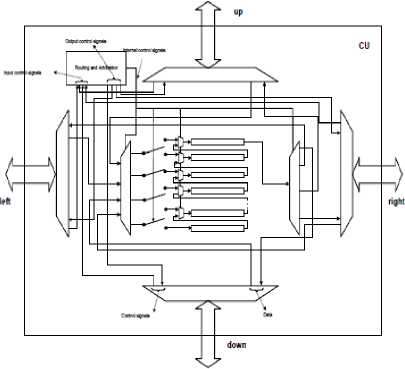
Remark : It may that several flits take the same way-out direction. In this case the switch takes 3 flits at maximum. A policy of arbitration must be adopted for the logic routing which manages the priority of sending of the flits. This policy is based on the rule of “the priority on right”. It is built individually for each port of Q-Switch (Fig.1-a).
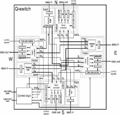
between packets stored and the next direction of the packets (See Fig.2).
-
• The Output Logic is made up of a semi crossbar composed of three inputs and four outputs; out- put buffer which consists of registers and a finite state machine (FSM). Incoming packets are stored into inputs according to priorities. If the neighbors of a switch are not busy, the first output of the semi crossbar is one of the adjacent switches. These packets are stored to registers, in the case where more than one packet choose the same output (direction). At maximum three messages can be stored in a output buffer. The finite state machine manages control signals and its role is also to avoid packets collisions. Moreover, it provides a central logic with information about the states of adjacent switches (wait situation, out signal, etc.).
-
• The Control Logic manages connections between the input and output ports of a switch, also handles the storage of packets that cannot be transferred to next directions, and informs the neighbors (which have sent the switch packets) that the switch cannot accept any other packets.
Fig.1–a. Architecture of Cu-Switch
-
B. Qnoc Architecture Topology
The topology of a QNoC architecture is usually a Mesh. The network has a grid-like form: boundary switches are connected to two or three neighbors, whereas other nodes are connected to four neighbors. The role of a switch is to pass data packets between elements (routers) of a QNoC architecture.
The switch (see Fig.1-b) is composed of:
-
C. Routing Process
The XY routing algorithm ( see figure 1-c) defines packets transmission: The packet travels first along x dimension, until the destination or elements unable to transmit in this x dimension, then it travels along y dimension using a reconfiguration mechanism ensures that for each transiting packet, either a path leading to the destination of the packet always exists or, if the packet is stored in some node unable to transmit data, the link between this node and the destination of the packet will eventually be restored.
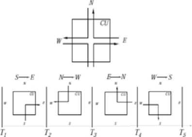
Fig.1-c. Right Priority
Fig.1-b. Structure of a Switch
-
• Input Register: Each incoming packet is stored in an input register when the Routing logic, computes the next direction of the packet (whether N, E, S or W). At maximum three packets are allowed per direction. The packets are transmitted to the output logic following the arbitration policy based on the rules of right priority which define priorities
-
IV. B-Event
The main reason to choose Event B [12] as a modeling language is the refinement, which allows a progressive development of models. When Event B also is supported by a complete toolset: RODIN [4] which provides features like refinement, proof obligations generation, proof assistants and model-checking facilities.
The Event B modeling language can express safety properties in two main structures: Contexts that express static parts of the model and machines that express dynamic parts.
The Event B model is defined by a machine contains events (or actions) that modify variables state and uses static information defined in a context. The general form of an event is expressed as follows
ANY x
WHERE G(x, u)
THEN u: | (P (u, u0)
END
Fig.2-a. Event B General form
These basic structures are extended by the refinement of models and this relates an abstract model and a concrete model by adding new events or variables, also allows to develop gradually Event-B models and to validate each decision step using the proof tool. The refinement relationship should be expressed as follows: a model M is refined by a model P, when P simulates M . The final concrete model is close to the behavior of real system that executes events using real source code. The refinement of a formal model allows us to enrich and ensure the model via a step-by-step approach and is the foundation of our correct-by-construction approach.
We have shortly introduced the Event B modeling language and the structures proposed for organizing the development of models. In fact, the classical refinement-based development of Event B requires a very careful derivation process, integrating possible tough interactive proofs for discharging generated proof obligations, at each step of development.
-
A. Context Structure
The Context contain many clauses introduced by a specific keywords as they are shown within Rodin platform, some clauses are introducing with modeling elements with labels (theorem axioms) which is generated automatically in the Rodin platform, such as “Sets” which defines the carrier set of the Context, “Constants” is the list of various constants introduced in the context, “Axioms” lists of the various predicates which will be present as hypotheses in all the proof obligations, “Theorems” lists of theorem which have to be proved within the context, “Extend” defines if a context is the extension of another (if exist).
-
B. Machine Structure
As the same of context, the machine had a specific keywords with labels introducing and automatically generated in the Rodin platform; “Refines” contains (if any) the machine which this machine refines; “Sees” list of contexts referenced by the machine, “Variables” lists the various variables introduced in a machine, “Invariants” the list of predicates which the variables must obey, “Events” lists various event in a machine (and they had a predefined syntax on the Rodin platform).
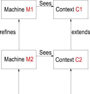
Fig.2-b. B-Event Concepts
-
C. Proof Obligations
The proof obligations define what is to be proved for an Event-B model. These proofs concern Invariant preservation, Feasibility, Fusion, … They are automatically generated by Rodin platform tool called the proof obligation generator, just to check contexts and machines texts and decide what is to prove in these texts, there are eleven rules for the proof obligation all defined and labeled inside the Rodin platform.
-
V. MODELING Qnoc ARCHITECTURE
The complexity of the architecture encourages us to break our formalization in different levels of observation. Our basic architecture is carried out by a mixing of two types of Switch (see figure one.) characterized by particular architectures represented in figure four.
-
A. First Architecture Design
There by, six levels are present here:
-
1) Abstract specification M0
The first model M0 is an abstract description of the service offered by the NoC architecture: the sending of the packet (p) by the switch source and the receiving of (p) by a switch destination. A set of switches (NODES) , a set of packets ( MSG), a function src, associating packets and their sources, a function dst, coupling packets and their destinations, are defined in context C0. The machine xyM0 uses (sees) the contents of the context C0, and with these, describes an abstract view of the service provided by the NoC architecture:
-
- An event SEND presents the sending of a packet(m), by its source(s), to switch destination(d).
-
- An event RECEIVE depicts the receiving a sent packet (m) by its destination (d).
Moreover, the model xyM0 allows us to express some properties and invariants:
Ran(received) ⊆ ran(sent) , this invariant expresses that each packet received by a switch destination has been sent by a switch source.
-
2) First refinement M1: Network introduction
The machine M1 refines M0 and introduces a network (a graph) between the sources and the destinations of packets. Some properties on the graph are defined in context C1: graph is non-empty, non-transitive and it is symmetrical.
The events in xyM0 are refined
-
- Event SEND: when a source sends a packet, the packet is put in the network.
-
- Event RECEIVE: a packet is received by its destinations, the packet has reached the destination.
New events are also introduced by M0:
-
- Event FORWARD: in the network a packet(p) transits from a node (x) to another node (y), until the destination (d) of the packet (p) is reached.
-
- Event DISABLE: A node is disabled. The node is not allowed to communicate with its neighbours (failure, etc). During the disabling of some nodes, we ensure that the packets transiting in the network will eventually reach their destinations (either after a reconfiguration of the network or by always letting a path to destinations available).
-
- Event RELINK: this event models the
reconfiguration of the network. Disabled nodes are re-enabled: the links between nodes are re enabled: the links between and their neighbors are restored, therefore allowing communications and packets of transfers. The reconfiguration of the network helps in demonstrating the safety of data transmission between a switch source and a switch destination.
The machine M1 also presents some properties of the system: ran(received) ∩ ran(store) ≠ ∅ , this Invariant demonstrates that a packet (p) sent by a source is either travelling in the network (store) or is received by the a destination.
-
3) Second refinement M2: channels introduction
This second refinement decomposes the event
FORWARD of M1 into two events:
-
- A refinement of the event FORWARD depicts the passing of a packet (p) from a switch (x) to channel (ch), leading to a neighbour(y).
-
- An event FROM_CHANNEL_TO_NODE models the transfer of a packet (p) from a channel (ch) to a connected switch(n).
The machine M2 also defines some properties: ran(c) ∩ ran (switch) = ∅ : this invariant expresses that each sent packet is either in a channel or in a switch. A sent packet cannot be in a channel and in a switch at the same time.
-
4) Third refinement M3: output logic
This refinement allows us to introduce the structure of a switch gradually. We express, in M13, that switches possess output ports. The abstract event FORWARD is further decomposed:
-
- The refinement of event FORWARD adds the fact that a packet(p), which is leaving a switch(x) and heading for a neighbour(y), first enters the output logic(op) of the switch(x) leading to (y).
Moreover, new properties and invariants are defined in M3:
Inv 1: ran(chan) ⊆ ran(sent)
Inv 2: ran(routingl) ∩ ran(chan) = ∅
The invariant inv1 expresses that each packet transiting in a channel (ch) has been sent by a source(s); inv2 presents the fact that a packet is either in an output port or in a channel, the packet cannot be in an output port and a channel between two switches at the same time.
-
5) Fourth refinement M4: Input register
introduction
This refinement (xyM4) adds input ports to the structure of a switch:
-
- The event SEND is refined: when a switch source (s) sends a packet (p), the packet(p) is put in an input port (ip) of the switch(s).
-
- The actions described by the abstract event FORWARD are decomposed :
o The event SWITCH_CONTROL, a refinement of FORWARD, models the passing of a packet (p), from an input(p), from an output port(op), to a channel (ch) leading to a target switch(n).
The machine xyM4 also presents properties and invariants:
Inv1: ran(inputbuffer) ⊆ ran(sent)
Inv2 = ran(inputbuffer) ∩ ran(chan) = ∅
The invariant exposes that each packet transiting in an input port(ip) has been sent by a source(s); inv2 presents the fact that a packet is either in an input port or in a channel, the packet cannot be in an input port and in a channel between two switches at the same time.
-
6) Fifth refinement M5: number of messages per switch
This refinement introduces the storage of packets in a switch: each output port of a switch can store a number of packets up to a limit (output places) of three messages. Packets can be blocked in a switch, because of wait or occupation signals from neighbors.
The event SWITCH_CONTROL is refined and adds the fact that following the transition of a packet from an input port of a switch (x) to an output port, if the switch (x) is not busy anymore, it sends a release signal to the previous switch linked to the input port. A new event RECEIVE_BUFFER_CREDIT models the receiving of a release signal by a switch(n).
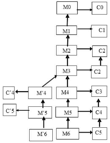
Fig.3. General Refinement Scheme
-
7) Sixth refinement M6: Algorithm XY
The last model describes the architecture of the network (graph): graph has a mesh topology. A numerical limit (nsize) is introduced to bound the number of routers in the dimensions x and y of the network topology; the network will be a regular 2D-Mesh, with a size (nsize x nsize); each switch is coupled with unique coordinates (x,y) with x ∈ [0..nsize-1] and y ∈ [0-nsize-1]. This model gives a fine-grained description of the structure of a switch.
-
- A switch has generally four output ports and four input ports (usually N, S, E and W), used for communication with neighbor’s.
-
- However, two cases are distinguished :
o Boundary switches in the corner have two outputs, and two input ports (N-E, N-W, S-E, and S-W).
o Other boundary switches have three output ports and three input ports (N-S-E, N-S-W
The cases of the XY routing algorithm are matched with refinements of event SWITCH CONTROL:
-
- SWITCH_CONTROL_LEFT case 1: a packet (p) is transmitted from an input port of a switch (x), to an output port, leading to neighbor (y), located at W. This event is triggered if the x-coordinate of the destination (d) (of the packet(p)) is inferior to the x-coordinate of the current node (x).
-
- SWITCH_CONTROL_RIGHT models Case 2: a packet (p) is transmitted from an input port of a switch (x) to an output port, leading to a neighbor (y) located at E. This event is triggered if the x-coordinate of the destination (d) (of the packet(p)) is superior to the x-coordinate of the current node(x).
-
- SWITCH_CONTROL_UP models Case 3: a packet (p) is transmitted, from an input port of a switch (x) to an output port, leading to a neighbor(y), located at N. This event is triggered if the y-coordinate of the destination (d) ( of the packet (p)) is superior to the y-coordinate of the destination (d) is equal to the x-coordinate of the current node(x), or the packet (p) cannot transit along the x-axis.
-
- SWITCH_CONTROL_DOWN models Case 4: a packet (p) is transmitted, from an input port of a switch(x), to an output port, leading to a neighbor (y), located at S. This event is triggered if the y-coordinate of the destination (d) ( of the packet(p)) is inferior to the y-coordinate of the current node(x), and either, if the x-coordinate of the destination (d) is equal to x-coordinate of the current node(x), or if the packet (p) cannot transit along the x-axis.
-
B. Second Architecture Design
-
1) VHDL code generation
This section shows the results of VHDL generated code allows us to have the possibility of blocs reusing.
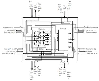
Fig.4-a. Easyswitch Architecture
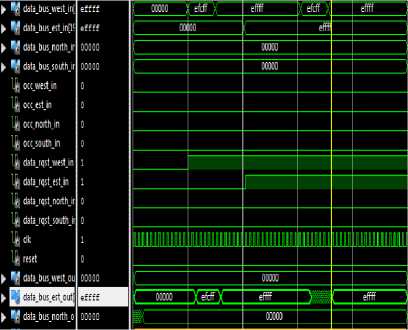
Fig.4-b. VHDL code Simulation
The file workbench is difficult because it is not automatically generated.
During Xilinx tool simulation we observe that:
-
- We need quantity of time of 15 ns in order to send between flits (piece of message);
-
- If we conserve the flit then the power consuming increases;
-
- All flits which arrive on one time slot will be routed before time slot period (strategy of output buffers).
-
- The phenomenon of head-of-line-blocking is
detected when data on the top of the file cannot access to output port and block all following data in the file.
Consequently: Deduced results after simulation: All flits need to be memorized. To deal with this problem, we introduce out buffers.
-
2) Improvement of architecture design
We present in this section formal design of CU-QNoC which represents the refinement of the specification presented on section IV.1 using decision design extracted from VHDL code simulation. We have introduced out buffers. The global schema of refinement is represented in figure 4 and the associated proof obligations are represented in table 2.
The refinement is represented in figure three. We remark that for context C’5 and the machine M4, there are more interactive proofs than automatic ones. This explained by the fact that a majority of these interactive proofs are quasi-automatic: the proofs did not need tough efforts (neither importing hypotheses nor simplifying goals etc.) , the mere usage/running of provers (provided by RODIN platform) allowed us to discharge these obligations. Contrary to the verification by simulation only, our work provides a framework for developing the network-on-chip architecture and the XY routing algorithm using essential safety properties together with a formal proof that asserts its correctness.

Fig.5. Auto Self-Reconfiguration Using IP Test on NoC Multi-node
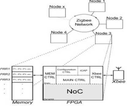
Fig.6. Auto-self Organized Wireless Network on Chip
-
VI. Testability Of Wireless Self-Organized Noc
Our system is inspired from the model proposed by [1] it is a system of self-reconfigurable multi-node, this net is composed of a set of self-organized wireless nodes that communicate using Zigbee network protocol (as shown in Figure five and six). Each node is independent. This allows maintenance and operational reliability of the system in case of failure. The model is based on the occupancy time of the router by sending a test packet to see if the router fails. The objective is to create an intelligent self-organizing system based on wireless technologies capable of self-management or self-distribution of tasks among different nodes. Dynamic task organization (IPs) is secured within the reconfigurable nodes through the NoC, while allowing the possibility of transferring the IPs to other nodes in case of failure detection. The dynamic self-organization is based on requests and responses generated between the different nodes of the network [2].
The architecture of a node is related to an FPGA circuit with a portion corresponding to a dynamic reconfigurable area implementing a multiprocessor system-on-chip (MPSoC)-based or adaptive 2D Mesh QNoC [3]. A node also integrates a Zigbee IP transmission protocol to ensure the inter-node communications system.
-
A. Reconfiguration Mechanism
The NoC structure of each node includes a mechanism for error detection line to achieve a detection mechanism out specific line. It is assumed in this case that the study of static parts of a failed node are faultless. When an error is detected within a NoC, the node is identified faulty. In the proposed approach, the offline IP tester is reconfigured in a delocalized non-faulty node to ensure the accuracy of test results. Thus, when a node is found defective, a test packet transmitted by transmission from the failed node. A volunteer node then handles the offline node failed the test. A node is designated volunteer if it satisfies the following rules:
Rule 1: Do not be a faulty node.
Rule 2: have the material resources to implement IP tester.
Rule 3: have the test packet configuration IP tester.
Rule 4: Do not be occupied by a priority.
Each potential node corresponding to these four rules can test the failed node. The failed node confirms the availability of the first test received, leading to the designation of the tester node. This latter implements IP tester through a dynamic partial reconfiguration using a packet from local test configuration. The off-line failed node test starts when the tester is configured IP (considered a priority). The tests are then made through the inter-node communications as the ZigBee protocol and the test method given in [1]. The node tester injects and receives via a router with its own NoC vectors answers to diagnose the failed node.
The test vectors and responses are injected into the NoC test using a TAS (Test Access Switch) and compared locally to identify faulty routers. Responses to test vectors defective routers are transmitted to the IP tester to be analyzed. The tester then determines the IP routers and defaulting parties erroneous router through position or erroneous bits in / responses to vectors. It follows a decision on the failed node (router reconfiguration, partial or complete deactivation).
-
B. Vertex Colored Algorithm
A distributed system is considered as a set of events composed of local events related to the agents and their local computations and global events like the use of the communication channel, messages sending/receiving... and is often seen as a graph (see figure seven), where the vertices are the nodes and the edges, direct communication links between them
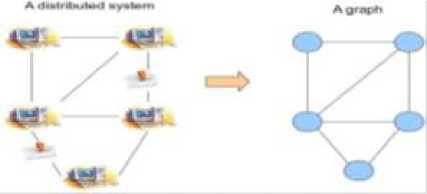
Fig.7. SoC Formalization onto Graph.
Symmetry breaking has always been a central problem in distributed systems. Several techniques have been developed in order to achieve it, such as Maximal Independent Set (MIS) algorithms, graph coloring algorithms [9]. In this section, we will focus on graph/vertex coloring algorithms . A vertex coloring algorithm is a method of graph labelling: its goal is to assign labels to the vertices of the graph. The labels are often assimilated to colors. Consequently, it is called graph coloring algorithm.
The coloring/labelling is done in such a manner that no two adjacent vertices of the graph share the same label/color: a proper coloring of a graph G = {V,E} (with V the set of the vertices of G and E the set of its edges), using a set of colors (COLORS cN | COLORS = {1..N}), is a function f such as (f: V> 5 COLORS |f(i) 5= f(j) if i^jeE). In this work, we focus on the development of algorithms using distributed techniques. In fact, there is little or no verification of the accuracy of previous algorithms considering some random numbers to define the process of secure coloration.'s Main contribution is still analyzing complexity and it can be done later on our models.
axm1 :NODES t 0
axm2 :PACKETS t 0
axm3 :src e PACKETS ^ NODES axm4 :dst e PACKETS ^ NODES axm5 :V p ■ pe PACKETS ^ src(p) t dst(p)
Fig.8. Abstract formal view of the system
-
C. Formalization using Event-B
As we explain previously the Wireless reconfigurable system could be represented as a graph, there are many practical applications of algorithms colored graph that include:
· Planning algorithms graph coloring can be used to control a set of nodes. Two nodes are considered adjacent when they may occur simultaneously. The aim is to prevent adjacent nodes occur at the same time. But in our case there may be two nodes that have the same job but two test nodes cannot even fix the failed node at the same time.
-
· Each node must be correctly colored in green, the correct node is a node that can send and receive packets.
-
· Each failed node must be colored red, a failed node is a node that cannot send or receive packets or one of the two.
-
· Each node test should be colored blue, a test node is a node chosen to correct the failed node.
-
1) Abstract level
We start with an abstract specification of the system by defining the role of the network send and receive packets (as shown in figure eight). So two sets will be defined in this level; existing nodes (NODES) and packets (packets) sent by a single source (src) and received by a single destination (dst). Sources are different destinations. The following axioms are described in the context of the abstract level as follows:
invl :sent e NODES ^ PACKETS inv2 :rcvd e NODES ^ PACKETS inv3 :ran(rcvd) C ran(sent)
inv4 :V s,p ■ seNODES Л pe PACKETS Л s^p e sent
^ s = src(p)
inv5 :V d,p ■ deNODES Л pe PACKETS Л d^p e rcvd
^ d = dst(p)
inv6 :V s1, s2, p ■ sleNODES Лs2eNODES Л pePACKETS
Л sl^pe sent Л s2^pesent^ s1=s2
V d1, d2, p ■ d1eNODES Лd2eNODES Л pePACKETS Л : d1^percvd Л d2^percvd^ d1=d2
Fig.9. Set of Invariants
We define the variables rcvd and sent that allow us to perform the SEND and RECEIVE actions. The following invariants are described in the abstract level the machine contains initial values of variables which are empty, the event SEND apply the action act1: sent ≔ sent ∪ {s ↦ p}, when the event receive apply the action act1: rcvd ≔ rcvd ∪ {d ↦ p}.
INITIALISATION ≙ act1 : sent ≔ ∅ act2 : rcvd ≔ ∅
Fig.10. Initialisation
-
2) Vertex colored graph introduction
We assume that the graph is given a set of nodes. Next, we define a set of colors (Red_Color, Green_Color, Blue_Color), whose components are the colors selected by the nodes during the execution of the algorithms of a graph coloring. We specify some properties of these constants:
green_color ≙
WHEREgrd5 : GrnClr ∉ CCorrectNode[GRAPH[ grd6 : CorrectNode↦p ∈ sent grd8 : CorrectNode↦p ∈rcvd
THEN act1 : CCorrectNode(node) ≔GrnClr
Fig.13. Corrected Node Coloration in the System
-
• Faulty Node:
Now the question is to calculate the function of coloration with red and we need to find an inductive property simulate the calculation of this function. Two variables will be added at this level; FaultyNode CFaultyNode and which are defined with the following properties:
INVARIANTS inv1 : FaultyNode ∈ NODES inv2 : CFaultyNode ∈ NODES ⇸ COLOR
CONSTANTS GRAPH Red_Color Green_Color Blue Color
Fig.14. Invariants
Faulty node is a failed node therefore be colored with red (as shown in Fig fourteen) the action will be as follow:
Fig.11. Constants
|
axm1 |
GRAPH ∈ NODES ↔ NODES |
|
axm2 |
GRAPH ≠ ∅ |
|
axm3 |
COLOR ≠ ∅ |
|
axm4 |
∀ c·c ∈ COLOR ⇒ c=Red_Color ∨ |
|
c=Green_Color ∨ c=Blue_Color |
|
|
axm5 |
∀ n·n ∈ NODES ⇒ n ∈ dom(GRAPH) |
|
axm6 |
NODES◁id ∩GRAPH = ∅ |
|
axm7 |
GRAPH = GRAPH ∼ |
|
axm8 |
∀ s·s ⊆ NODES ∧ s ≠ ∅ ∧ GRAPH[s] ⊆ s ⇒ NODES ⊆ s |
Fig.12. Axioms
-
- Axm5 axiom expresses that all vertices belong to the graph GRAPH, they are not isolated,
-
- Expresses axm6 axiom that the graph of the graph is irreflexive: the neighbor of a peak in GRAPH be another vertex, and not itself,
-
- Axm7 axiom expresses that the graph of the graph is symmetric,
-
- Axm8 axiom expresses that the graph graph is connected.
-
• Correct Node:
In this refined machine level abstract level we will consider all node can send and receive packet thus allowing us to colored green (as shown in Figure thirteen). CCorrecteNode the variable is defined with the following property:
inv1: CCorrectNode ∈ NODES ⇸ COLOR
This property defines a node as part of all the colored nodes, then all the net will be colored in green applying the event green_color:
red_color ≙
WHERE grd3 : rdClr ∈ COLOR grd4 : node ∈ dom(GRAPH)
grd5 : node = FaultyNode grd6 : rdClr ∉ CFaultyNode[GRAPH[{node}]]
grd7 : FaultyNode ↦p ∉sent grd8 : FaultyNode ↦p ∉rcvd
THEN act1 : CFaultyNode(node) ≔rdClr
Fig.15. Faulty Node Coloration in the System
-
• IP Test Node :
In this level the calculation of the selection function of the node test is specified in a simple way to break the complexity of the role of this node, then just follow the rules of choice of the node test and the rest is considered procedure to apply after selecting the node test
|
blue_color ≙ |
|
|
WHERE |
|
|
grd4 |
node ∈ dom(GRAPH) |
|
grd5 |
node = TestNode |
|
grd6 |
blClr ∉ CTestNode[GRAPH[{node}]] |
|
grd7 |
TestNode ↦ p ∉ sent |
|
grd8 |
TestNode ↦ p ∉ rcvd |
|
grd9 |
TestNode ≠ FaultyNode |
|
grd10 |
: src(BitstreamPacket)= TestNode |
|
grd11 |
: dst(BitstreamPacket)= TestNode |
|
THEN |
|
|
act1 : |
CTestNode(node) ≔ blClr |
Fig.16. Blue Color Node
- Rule 1: Do not be a faulty node. This is defined in the grd9
-
- Rule 2: have the material resources to implement IP tester.
-
- Rule 3: Bitsream have the configuration of the IP tester. The grd10 grd11 and respect this rule because if the node does not have the file reconfiguration may receive from our a node.
-
- Rule 4: do not be occupied by a priority. The grd7 and grd8 means that this node is not busy with sending or receiving packets.
After follow the rules node can be chosen as test node (as shown in Figures 15 and 16) and the action of the blue color attribution for a node test will be performed.
-
VII. Comparative Study Between Informal And Formal Approaches
a- Informal approach :
Using heuristics to improve QNoC architecture: several years to improve architecture:
Non-existence of support worked as container on which we can improve architecture. We must really implement to test it efficiency.
Advantages: temporal constraints can be measured.
Disadvantages: real implementation of cell tests, limitation of node number under NoC. (5 to 6 nodes order)
-
• Auto-organized wireless network [1]:
-
■ Platform : ML 507 / Virtex 5 FX70 Digilent
Nexys 3 board / Spartran 6
-
■ Tools : Xilinx/ Xbee protocol
-
■ Constraints : 5x5 2D-mesh NoC
-
■ Wireless network
-
• Test ANoC platform [22]
-
■ Routers and wrappers were modeled using
System C and VHDL or Verilog netlist.
-
■ Co-simulation was realized by ModelSim tool of Mentor Graphics [26].
-
■ Constraints: 3 x 3, 3 x 4,4x5 2 D-mesh
-
■ Single Soc.
b- Formal approach:
It is characterized by
-
- General approach on which we can designing architecture from complete high level point of view.
-
- Rigorous syntax to describe problem.
-
- Possibility to generate code
-
- Using high level object (graph theory) to reason about some problems.
VIII. Conclusion
The paper aims to define a new design flow for the future on chip communications. The main goal of this is to provide a formal language of software and hardware platform for design space exploration of such architectures. Regular-topology NoC is proposed as on-chip communication architectures primarily using switching and routing techniques.. NoCs are a rather new field of research. Regular topology NoCs are developed as they are inspired by general purpose multicomputer networks.
Our method concerns the horizontal and vertical validation between design layers. We refer us to formal method event-B [6, 2] to structure embedded system design life cycle. Event-B is a method for specifying, designing and coding software systems: the concept of generalized substitution and on structuring mechanisms (machine, refinement, and implementation). The concept of refinement is the key notion for developing B models of (software) systems in an incremental way.
There are several phases which we exploit to improve the systems by optimizing our architecture. We exploit interactivity between VHDL code simulation and Rodin specification refinement. The feedback from VHDL code to B-event specification will be also exploited. [11]
A case study for the formalization of the most abstract level of the NoC to the lowest level in event-B was presented in a hierarchical way. The B-event helps to identify invariants for reliable systems. It finds invariants for a correct and meaningful model represents a significant challenge, for it ensures the safe operation of various systems. In summary, we have proposed a switch NoC architecture and its proof process (B formalism). The results of the proof process have made it possible to validate the operations of our architecture. The refinement allows us to give different views of our architecture and to validate. We can integrate our approach in general frame work of FPGA NoC based Design using formal refinements and produce formal specifications of particular architecture which helps to document all the design process.
As future perspectives, we project to establish formal rules to SoC which are heterogeneous and application-specific/domain-specific. In SoC, computation nodes (units) have often different communications requirements and geometry. There are several limitations in using regular-topology NoC for heterogeneous application/domain-specific SoC such as poorly supported communication locality, treated equally communication requirements of function units, a low utilization of abundant network resource, and different-sized function units which do not fit correctly in floor plans. This research work will focus on irregular topology NoCs and FPGA dynamic reconfiguration by taking into account the algorithm specifications and any potential parallelism. It appears interesting to analyse the complete design flow from algorithm specifications till the VHDL (RTL) generation of irregular NoCs topologies that support dynamic reconfiguration. Dynamic reconfiguration can be considered at different levels: inserting/ removing of processing units, dynamic scheduling, topology modification and network size changes, adaptation of the buffer size.
References Formal and Informal Modeling of Fault Tolerant Noc Architectures
- M. Heil and C. Tanougast: “Fault-tolerant self-organized mechanism for networked reconfigurable MPSoC” Codit’14. Metz.
- Killian, C. Tanougast, F. Monterio, and A. Dandache, “A new efficient and reliable dynamically Reconfigurable Network-on-Chip", Journal of Electrical and Computer Engineering, special issue Design and Automation for Integrated Circuits and Systems, Volume 2012, Article ID 843239, 16 pages, Hiwdawi, 2012.
- E. Bolotin, I. Cidon, R. Ginosar, A. Kolodny, “QNoC: QoS architecture and design process for network on chip” Journal of Systems architecture. 2003.
- Project RODIN. Rigorous open development environment for complex systems. http://www.eventb.org/, 2004-2010.
- M. Kamali, Luigia Petre, K. Sere, M. Daneshtalab Refinement-Based Modeling of 3D NoCs 2011 14th Euromicro Conference on Digital System Design.
- M Belarbi: Formal Modelling of Real-Time Embedded Automotive Architecture. Society of Design and Process Science Journal. JIDP, Volume 13, Number 2, 2009.
- H. Daoud, C. Tanougast, M. Belarbi and D. Mery, "Formal verification properties for Rapid Prototyping Using Fault Tolerant NoC-based Architecture", First International Workshop on Mathematics and Computer Science, Dec. 2012, University Ibn Khaldoun of Tiaret.
- Butler MJ (2009) Decomposition structures for Event-B. In: Leuschel M, Wehrheim H (eds) Proceedings of 7th international conference on integrated formal methods, IFM2009, Dusseldorf, Germany, February 16–19, 2009. Lecture notes in computer science, vol 5423. Springer, Berlin, pp 20–38.
- M. B. Andriamiarina, D. Méry, and N. K. Singh. Revisiting Snapshot Algorithms by Re?nement-based Techniques. In PDCAT. IEEE Computer Society, 2012.
- A. Hariche. M. Belarbi. and H. Daoud(2013), new Operators-Based Approach for the Event-B Refinement: QNoC Case Study IEEE ICM’2013, Beirut 15-18 Dec. 2013.
- A. Hariche. M. Belarbi. and H. Daoud(2012), Based B Extraction of QNoC architecture properties IWMCS’2012, Tiaret 16-17 Dec. 2012. Published by MomaJournal, Vol 1, Issue 2 (2012). ISSN N° 2253-0665.
- Abrial J.-R., The B book: assigning programs to meanings, Cambridge University Press, 1996.
- Abrial, J-R, Butler MJ, Hallerstede S, Hoang TS, Mehta F, Voisin L (2010) Rodin: an open toolset for modelling and reasoning in Event-B. STTT 12(6):447–466.
- Bjerregaard and S. Mahadevan. A Survey of Research and Practices of Network-on-Chip. ACM Computer Surveys, 38(1), 2006.
- K. Goossens. Formal Methods for Networks on Chips. In Proceedings of the Fifth International Conference on Application of Concurrency to System Design, ACSD’05, pages 188–189. IEEE Computer Society, 200.
- Killian, C. Tanougast, F. Monterio, and A. Dandache, “Online routing fault detection for reconfigurable noc,” in International Conference on Field Programmable Logic and Applications, 2010.
- Killian, C. Tanougast, F. Monterio, and A. Dandache. Online routing fault detection for recon?gurable noc. In International Conference on Field Programmable Logic and Applications, 2010.
- J.S. Chenard, S. Bourduas, N. Azuelos, M. Boul′e, and Z. Zilic. Hardware Assertion Checkers in On-line Detection of Network-on-Chip Faults. In Proceedings of the Workshop on Diagnostic Services in Networks.
- Zhu, Q. and Matsuda, A. and Kuwamura, S. and Nakata, T. (2002) An Object-Oriented Design Process for System-on-Chip using UML Proceedings of 15th International Symposium on System Synthesis, New York, 2-4 October 2002, pp. 249-254. doi:10.1145/581199.58125.
- H.Daoud, C.Tanougast, M.Belarbi_, M. Heil_ “Formal Specification and Verification of wireless networked self-organized Systems on Chip” Cofid’14. Metz.
- X.-T. Tran, J. Durupt, Y. Thonnart, F. Bertrand, V. Beroulle, and C. Robach. Implementation of a Design-for-Test Architecture for Asynchronous Networks-on-Chip. In Proceeding of the 1st ACM/IEEE International Symposium on Networks-on-Chips, NOCS 2007, pp. 216{216, New Jersey, USA, May 2007.
- Morin-Allory, K. and Fesquet, L. and Borroine, D slopp(2006) Asynchronous Assertion Monitors For Multi-clock domain system veri?cation, 14-16 June. Seventeenth IEEE International Workshop on Rapid System Prototyping.
- R. Allur, D.L. Dill, “A theory of timed automata”, Theoretical Computer Science. 1994, Vol. 126, pp. 183-235.
- M. Butler and I. Maamria “Mathematical Extension in Event-B through the Rodin Theory Component” Research report 8 June 2010.
- Mentor Graphics www.mentorgraphics.com.
- M. Hosseinabady, A. Banaiyan, M.-N. Bojnordi, Z. Navabi ?A Concurrent Testing Method for NoC Switches”. in Proceedings of the conference on Design, automation and test in Europe: Proceedings, ser. DATE ’06. European Design and Automation Association, 2006, pp. 1171–1176.
