Formalizing the Software Engineering Process Using a Graphical Software Process Modelling Formalism

Author: Hisham S. Khdair, Mohammed M. Awad, Zulaiha A. Othman
Journal: International Journal of Information Technology and Computer Science(IJITCS) @ijitcs
Article in issue: 6 Vol. 9, 2017.
Free access
Software process modelling has recently become an area of interest within both academia and industry. It aims at defining and formalizing the software process in the form of formal rigorous models. A software process modelling formalism presents the language or notation in which the software process is defined and formalized. Several software process modelling formalisms have been introduced lately, however, they have failed to gain the attention of the industry. One major objective of formalizing the software process that has ever been an issue of research, is to enhance the understanding and communication among software process users. To achieve this aim, a modelling formalism has to offer a common language to be well-understood by all software process users. BPMN presents a graphical-based widely accepted standard formalism, mainly aimed at business process modelling. This paper illustrates a software process modelling formalism based upon BPMN specifications for representing the software process, named as, SP2MN. The paper also demonstrates the applicability and evaluation of the proposed formalism by; utilizing the standard ISPW-6 benchmark problem, in addition to comparing the expressiveness of SP2MN with similar software process modelling formalisms. The evaluations prove that SP2MN contributes in enhancing software process formalization. SP2MN, accordingly, can be used as a standard software process modelling formalism.
Software process, Software process model, Software process modelling, Software process modelling language, BPMN
Short address: https://sciup.org/15012652
IDR: 15012652
Text of the scientific article Formalizing the Software Engineering Process Using a Graphical Software Process Modelling Formalism
Published Online June 2017 in MECS
A software engineering process (or simply, software process) is defined as the partially ordered set of activities to be undertaken to manage, develop and maintain software systems and to be carried out by the human agents to pursue the goals of software engineering [1, 2] In order to achieve a precise and rigorous specification of these activities, researchers in the field have agreed that defining and formalizing a software process has to follow an engineered disciplines and technologies as it is followed in the conventional software engineering [3].
Software process engineering can be defined as the systematic and engineered paradigm that deals with all engineering activities related to designing, constructing and adapting the software process [4]. Software process modelling is the most prominent software process engineering paradigm. In software process modelling, the modelling of the software process refers to the definition and formalization of software processes as models. Finkelstein et al. [5] define a process model as the description of a process expressed in a suitable software process modelling formalism. A software process modelling formalism, in turn, is the language (or notation) that is used to support the act of software process modelling.
Counting on a rigorously formalized software process within an organization or for a specific project is a basis for improvement from the point of view of both, the product quality as well as the process quality and productivity. Among the benefits of software process modelling/formalization which are worth highlighting are:
providing a basis for software process analysis, evaluation and improvement, and a source of information for training new developers. Software process explicit definition enables certification, evaluation and improvement according to standards such as CMMI, which may also bring commercial benefits [6-8].
Curtis et al. [9] present some of the specific goals and benefits of software process modelling, as: facilitating user understanding and communication, providing automated execution support, or supporting software process management and improvement. Based on that, defining and/or identifying software process modelling formalism to be used is a main concern of software process modelling. The right formalism to be chosen should fulfil one of the major goals of software process modelling.
Facilitating the understanding of software process models and enhancing the communication between different software process users has been an ever existing concern in software process modelling. Software process users are of many types, ranging from, naïve users such as customers and stakeholders who don’t have understanding about technical issues, to software executives and developer, software engineers, project managers, etc. It is important for all those users to have a common understanding about the software process in order to communicate. Therefore, the formalism has to be easily understandable by all of such different kinds of users, and hence the most likely formalism for such an aim is a visual graphical-based SPML [10, 11].
There are several graphical-based SPMLs/Formalisms have been proposed, for example, state-transition [12, 13], petri-nets [14], IDEF-based [15], etc. Such SPMLs have practically put a quite robust emphasis on formality, strong notation, syntax and semantics. However, they have failed to present that common ground language that is familiar and acceptable by software process users and practitioners. The continuing proliferation of such first-generation SPMLs has naturally raised the need for standardizing software process descriptions. The success of the Unified Modelling Language (UML) standard for traditional software modelling has allured many researchers to adapt it into software process modelling, for example, the SPEM standard of OMG [16], the PROMENADE language [17], Di Nitto et al. approach [18], UML4SPM [19], and so on.
Business Process Model and Notation (BPMN) is another promising global standard for process modelling and it is presented as one of the most important components of successful Business-IT-Alignment. BPMN was mainly intended for business process modelling to provide a notation that is readily understandable by all business users, from the business analysts, to the technical developers, and to the business people. This paper deploys and adapts such a modelling techniques for the aim of software process modelling within a new SPML, named as: Software Process MetaModel and Notation (SP2MN). SP2MN aims to contribute in enhancing the software process understanding and communication as a major goal for software process modelling.
SP2MN provides a graphical-based notation for generic software process modelling, adapted from BPMN. The constructs and concepts of software process modelling are represented by a high-level abstract metamodel. Providing an expressive SPML was the main design objective for SP2MN, where its expressiveness is considered by its capability to express the most common software process modeling concepts [20, 21]. In order to check if SP2MN meets its design objective, an evaluation is undertaken by demonstrating and expressing the formalization of the 6th International Software Process Workshop (ISPW-6) software process example problem [22] according to SP2MN modelling specification and notation. Furthermore, the outcome models and their associated expressiveness issues are compared to the provided solutions of other SPMLs where possible.
This paper is organized as follows. Section II studies and represents the expressiveness and technical adequacy of BPMN against other modelling techniques. Furthermore, it studies the suitability of BPMN for software process modelling and identifies the extensions and enhancements to suit software process modelling if required. Section III gives an overview of SP2MN. Section IV and V provide brief descriptions of the SP2MN solution to the ISPW-6 software process problem and the Agile Scrum software process. Section VI discusses the lessons learned. Finally, Section VII presents the conclusions of the paper.
-
II. BPMN Specification
BPMN presents a graphical notation, widely accepted for business process modelling. It is maintained by the object management group (OMG) [23], which is established through other world-wide standards such as UML. It is based on a flowcharting technique, very similar to activity diagram in UML.
The primary goal behind BPMN is to provide a standard notation that is easily understandable by different kind of process users. Consequently, BPMN serves as a common language, bridging the communication gap that frequently occurs between process design and implementation.
BPMN provides a large palette of expressive notation which is able to represent the real process’s elements and concepts. Table 1 below shows the graphical elements of BPMN used to express main process modelling concepts, such as: process’s activities and steps, events and states, decision nodes, flow connections and interdependencies, process participants, as well as other elements.
Table 1. BPMN specification - elements and notation
Element
Description
Symbol
Activities and Tasks
An activity is a generic term for work that company performs in a process. The types of activities that are a part of a process model are: sub-process and task. Which in turn, allows more hierarchy and decomposition of the process model.
Task
$ubProce$$ 0
Events
An event is something that happens during the course of a process. There are three types of events, based on when they affect the flow: start, intermediate, and end.
Stat
Intemnediate
End
n
S Ё
5 I*
Exclusive DecisionWerje
Gateways/ Nodes
A gateway is used to control the divergence and convergence of sequence flows in a process. Thus, it will determine branching, forking, merging, and joining of paths.
DalB-teedXOR Event-based XOR
Inclisive Decism/Merge (OR)
Complex DecisionMerge
Parallel FatiJoin (AND)
Flow Connections
Connecting objects are the ways of connecting the flow objects to each other or other information, as: sequence flow, message flow, and association. While sequence flow itself can be, conditional, conditional, default, or exceptional flow.
Sequence Flew
О.......................
Message Flow
>
Sequence Flow
Conditional
Sequence Flow
Default
Sequence Flow
Association
Data Objects and Artifacts
Data objects provide information about what activities require to be performed and/or what they produce, data objects can represent a singular object or a collection of objects. Additional artifacts are text annotations or group.
Data Object
G roup
Annotation
I
Swimlanes
For grouping the primary modeling elements through swimlanes, this happens by two means: pools and lanes. A pool is a graphical container for partitioning a set of activities from other pools. A lane is a subpartition within a process, sometimes within a pool, and will extend the entire length of the process. In BPMN they are represented mostly horizontally.

Compared to other standard process modelling formalisms, e.g. UML Activity Diagram [24] (for a wider comparative analysis, see [25-33]), BPMN provides a high level of ease of understanding of its process models. It also offers a comprehensive support of the control-flow and data perspectives.
Yet, BPMN brings a series of enhancements to process modeling, especially, with regards to the graphical elements used to represent the control-flow patterns and the workflow data patterns. Major enhancements concern with: exclusive, parallel and event-based gateways, varied kind of tasks, such as human, service and business rule tasks, sequential multi-instance activity, different kinds of data objects, intermediate and non-interrupting events for a process, sub-processes, loop-processes and event sub-processes for a process, and so on. Furthermore, BPMN provides simpler graphical symbols for representation, for example, there are aspects of business processes that can be modeled in BPMN using only one symbol, but for which the representation in UML AD requires the use of a group of symbols.
It can be concluded that BPMN is a convenient, yet promising technique for modelling and formalizing the software process. However, software process modelling has specific modelling needs, which distinguish it from business process modelling. In order to represent the actual software process in real software process modelling contexts, BPMN specifications have to be adapted and extended.
-
III. Software Process Modelling
A software process is not abstracted by only one single view. The literature of software process modelling shows several proposed software process models that intend to convey different views of the software process [34].
There are activity-oriented software process models ([16, 35] which focus on the activities in the software process, where product-oriented software process models [36, 37] which concern about the software artifacts and output products of the software process. Furthermore, there are resource-focused software process models which focus on the resources that are needed or provided to the software process, as well as role-oriented software process models which concern about the skills and the responsibilities of the software process performers [16]. For more software process modelling approaches comparison, see ([38, 39]).
As a conclusion, we define [40] a set of common concepts to be included in a common software process modelling formalism, and accordingly, an expressive software process modelling language based-on BPMN has to encompass these concepts (designed in the next Section). The set of concepts are summarized in Table 2 below, where the first and second columns describe the concept, while the third relate such concept to the source software process model/s.
Table 2. Defined software process modelling concepts for an expressive modelling language
|
Concept |
Definition |
Representative process model/s |
|
Work Unit |
A software process defines the structured work unit to be performed to develop a software system. Such work unit delineate the work to be performed along a timeline or lifecycle. |
OPF [1], represented as “Work Unit”, SPEM [2], represented as “Work Definition”. |
|
Activity |
An activity is a high level work unit. An activity models a cohesive collection of tasks for manipulating one or more work products. A task is therefore a type of work unit but with finer granularity than an activity. Techniques state how a task is to be undertaken. |
OPF [35], represented as “Activity”, “Task” and the associated “Technique”. |
|
Work Product |
A work product models anything of value that is created, accessed and used, or modified during the performance of work units. Thus, expressing the work product state is essential during the software process performance. Work products are of different types and themselves have many representation and modelling forms. |
Entity Process Model [3], SPEM [16], Cossentino et al. approach [4]. |
|
Role |
A role, models a collections of cohesive and interrelated responsibilities that are played by one or more agent/actor (individuals or a set of individuals). |
SPEM [16], OPF [35], represented as “Indirect Producer”. Bendraou et al. approach [5], represented as “Responsible Role”. |
|
Actor |
Is a performer that represents one or more individual human actor/ agent that is assigned (i.e. by a project manager) to perform one or more role. A human actor might use one or more tool (i.e. software application) in performing the role. |
OPF [35], represented as “Direct Producer”. |
|
Stage |
A stage represents the intended timing of the performance of a temporally-cohesive set of work units during the enactment of a software process. |
SPEM [16], represented as “Phase”, “Iteration” as subtype of an activity and consequently a work definition, OPF [35], “Stage” with association to work unit. Cossentino et al. approach [36], represented as “Phase” with association to activity. |
|
Lifecycle |
A lifecycle consists of all phases during which a single system, application, or major component is produced, used, and retired. |
OPF [35], SPEM [16]. |
|
Context |
A context represents the situation and the intention of an actor at a given moment of the project. The key concepts of Context that it is composed of a Situation and an Intention. The situation is a part of a work product under a specific circumstance. The intention represents the objective that an actor wants to achieve according to the situation. |
Ralyte et al. approach [6], SO2M [7], NATURE [8]. |
-
IV. SP2MN: A Bpmn-Based Software Process Modelling Formalism
Software Process Meta-Model and Notation (SP2MN)
is a software process modelling language. SP2MN is mainly a software process modelling language which is based on, adapted and extended BPMN 2.0 notation to suit the software process modelling context, as discussed previously in the last two sections.
As a language, it is composed of syntax and semantics
-
[44]. The syntax of a language means the structure of that language. The syntax is also divided into two types. The abstract syntax in SP2MN presents the rules and the grammar of the language, it is represented here, as the name refers, by a meta-model (a conceptual model of the concepts included in the language [40]). Whereas, the concrete syntax in SP2MN represents the graphical notation -which is based on BPMN notation. For detailed information on SP2MN, see [40].
The main adaptions and extensions of BPMN 2.0 into
SP2MN are summarized in Table 3 below. The adaptions and extensions are made with reference to the BPMN constructs and notation in Table 1 and the defined concepts and constructs of software process modelling in Table 2, respectively.
Because of the limited space, the adopted exact elements from BPMN 2.0 specification are eliminated from the below table, such as, events, gateways and flow controls.
Table 3. SP2MN Notation
Software Process Concept
Work Units (Tasks or Activities)
Notation (Graphical Symbol)
Techniques
Work Products (Artifacts, Deliverables, Outcomes)


Textual Artifact

Deliverable
Role
Actor
Life Cycle
Stage
Graphical Artifact

Outcome

Primary Role

Additional Performer


Human Actor Tool


Description
Work Units are represented by SP2MN Tasks and Activities. SP2MN Activity reuses BPMN Sub-Process construct. Likewise, SP2MN Task reuses BPMN Task construct.
A Technique is a new construct provided by SP2MN as an extension to BPMN Artifact
SP2MN Work Product extends BPMN Data Object construct with three kinds of Work Products. SP2MN provides Artifacts, Deliverables and Outcomes as three kinds of Work Products. SP2MN Artifacts are of two types, Graphical Artifacts or Textual Artifacts.
SP2MN provides two kinds of Roles as Primary Performers and Additional Performers. The BPMN Lane element is reused only for representing a SP2MN Primary Performer, where assigned tasks to a specific Primary Performer are grouped within its represented Lane. Yet, when there is a Work Unit (Activity or Task) assigned to a different additional
Role, this is represented by SP2MN Additional Performer construct as a new BPMN Artifact.
An Actor is a new construct provided by SP2MN as an extension to BPMN Artifact. SP2MN provides two types of Actors, which is either a Human Actor or a Tool.
A Lifecycle is a new construct provided by SP2MN as an extension to BPMN Artifact.
SP2MN Stage construct is represented by BPMN Group element.
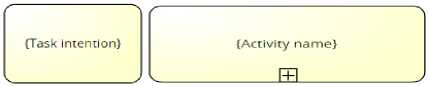
Context (Intention plus situation)
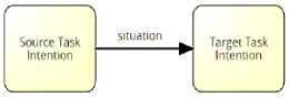
The Context construct is composed of Intention and Situation. The Intention construct which is associated to a certain Task is represented as the Task label. The Situation construct is represented as the Sequence Flow label (ID).
-
V. Formalizing The ISPW-6 Software Process Example Problem Using Sp2mn
The ISPW-6 software process problem has been produced as a standard benchmark software process modelling example problem [22]. A problem that comprehensively exercises the various modelling approaches being developed, throughout coverage of several important components of real-world software processes. The primary purpose behind that was to facilitate understanding, assessing and comparing the various approaches that are being proposed for software process modelling.
The ISPW-6 problem concerns with a software change request occurring at the end of the development project. A number of activities are defined including: Modify Design; Review Design; Modify Code; Modify Test Plans; Modify Unit Test Package; and Test Unit. Some activities may be executed in parallel, while others have to be executed in a sequential manner. In each activity, there are also defined roles, tools, source files, and preconditions and post-conditions which must be respected by the software engineers to complete the task. In general, the description of ISPW-6 software process problem mainly consists of the following elements:
-
• Responsibilities: which describe the responsible roles within the software process, e.g. Project Manager, Design Engineer, QA Engineer and so on.
-
• Steps (work units): which describe the actions to be performed by one or more responsible role, such as: Modify Design, Review Design, Modify Code, and so on.
-
• Inputs/Outputs: which describe the work products required or produced by each specified step.
-
• Constraints (pre-conditions and post-conditions): which describe the sequencing of steps, which in turn is useful for representing the Context concept.
For a detailed information about how are these elements presented in ISPW-6 problem scenario, refer back to [22].
“Fig. 1,” represents a portion of the overall software process model solution according to SP2MN specification for ISPW-6.
The figure shows the modelled tasks, such as “Manage Plan”, “Manage Resources”, “Modify Design”, “Modify Code” and so on. It expresses the “Project Manager” role as a lane that contains all the tasks that are assigned to this role. “Design Engineer” represents another role with its assigned tasks.
For more elaborations, the first task, “Manage Resources” starts when it receives a message signal from “Configuration Control Board”, which represented as an external entity to the process. The task is valid when the situation “change is authorized” is valid. The Manage plan task takes “Requirements Change” and “Project Plans” as input work products. Both products are kind of deliverable work products (refer to (Table 3)). The task has the Project Plans product as an output product. Project Plans has a textual kind of representation formalism; therefore, it was represented as a textual artifact in the model. Project Plans status is set as updated. Updated project plans are the triggering situation for the following intention of the task “Manage Resources”. Manage Resources task produces “Task Assignments and Scheduled Dates” work product, where the creation of this product triggers the other subsequent tasks, and hence other all tasks are forked by a Parallel Gateway to be executed in parallel before joining again at the end of the process when completing all tasks.
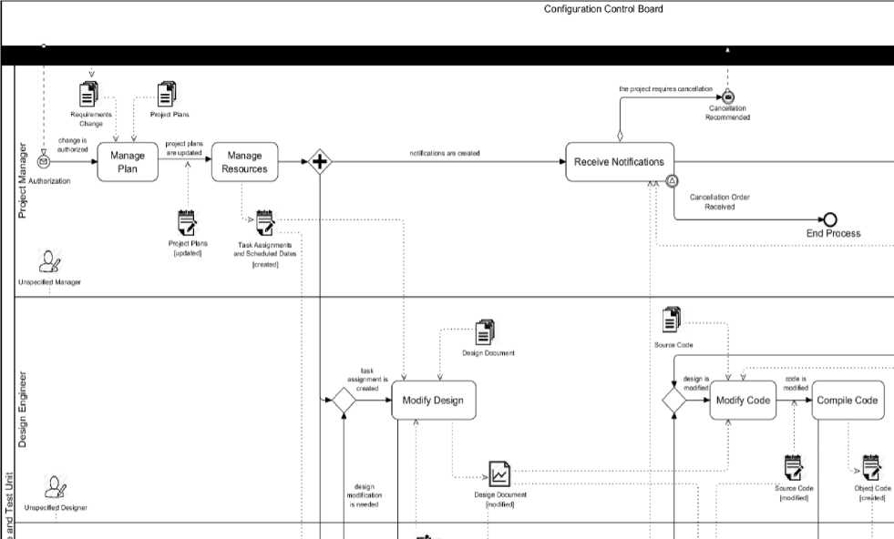
Fig.1. ISPW-6 software process model according to SP2MN
-
VI. Results
The following discussion focuses on the issues relating to the effectiveness of representation and expressiveness of the SP2MN notation as compared to other SPMLs.
SP2MN has provided solutions to the ISPW-6 problem which have demonstrated that SP2MN notation is simple and intuitive. This is seen as due to the reasons are that SP2MN adopts a visual syntax, and the general structure of the SP2MN graphs resembles the structure of a conventional process models.
The expressiveness power of the proposed approach with compared to other similar SPMLs based on standard ISPW-6 software process problem is demonstrated in Table 4 below.
Table 4. Expressiveness of SP2MN compared to similar languages
|
ISPW-6 software process elements to be represented [22] |
As represented by [12] |
As represented by UML4SPM [45] |
As represented by this approach (SP2MN) [9] |
|
Work units/steps |
Represented as tasks. |
Represented as abstract activity concept only. |
Work units are represented as tasks, subprocesses. Moreover, the technique, as well as the stage and lifecycle concepts representations are supported. |
|
Work products (as inputs or outputs) |
Work product is represented. |
Work products and product states are represented. |
Work products, product kinds (deliverable, or artifact), product types (Graphical, or Textual), and representation formalism, in addition to product state are represented. |
|
Responsibility (Roles) |
Roles are represented. |
Roles are represented. |
Roles, primary and additional roles are represented. |
|
Actors (Although it is not specified in ISPW-6) |
Human actors and tools representation is supported. |
Human actors and tools representation is supported. |
Human actors and tools is supported. |
|
Constraints (Pre-conditions and Post-conditions) |
Post-condition is implicitly represented by the (finishing state) concept. |
Only represented by abstract pre-condition and postcondition. |
Pre-conditions are represented by intentions which are associated to tasks. Postconditions are represented by situations that are needed to trigger such tasks. |
|
Communication between participants, roles and their work units. |
Some events are used as means to trigger actions that allow stage/task state change. |
Massage communication between activities, and send signal actions. |
The software process participants are clearly represented by separate pools and the communication flow between them is by messages. The communication within the process is by signal events and data association flow. |
|
Activities Sequence and Coordination |
Represented by event flow concept. In addition to, AND, OR stages. |
Represented by control flow, object flow, and control nodes. |
Represented by sequence flow. As well as, parallel, inclusive and exclusive gateways and nodes. |
|
Software process events/states |
Start stage, and end stage. |
Start, end, message, change and time events. |
Represented by rich set of, start, intermediate, and end events. |
|
Modularization (Although it is not required by ISPW-6) |
Not handled. |
Supported implicitly and partially by the represented UML software activities. |
It is supported by tasks that are represented as autonomous sections (associated with Contexts ), which are eligible to be defined and represented as method services. |
-
VII. Conclusion
A major issue for modelling the software process is to enhance the understanding and communication among software process users. For this aim a software process modelling language in use has to be simple and adoptable.
SP2MN concerns the reusing and adapting BPMN 2.0, as a clear, simple, understandable, as well as being standard, widely acceptable and used formalism for process modelling. SP2MN also extends BPMN in order to provide an expressive software process modelling language.
This paper has presented an evaluation of SP2MN modelling on the international standard benchmark ISPW-6 software process example problem. This case study has proven the validity of SP2MN.
Moreover, the evaluation with other similar SPMLs has proven the effectiveness of SP2MN in terms of the language syntax and semantics.
References Formalizing the Software Engineering Process Using a Graphical Software Process Modelling Formalism
- B. Henderson-Sellers and J. Ralyte, "Situational Method Engineering: State-of-the-Art Review," J. UCS, vol. 16, no. 3, pp. 424-478, 2010.
- J. Lonchamp, "A Structured Conceptual and Terminological Framework for Software Process Engineering," in ICSP, 1993, pp. 41-53.
- L. Osterweil, "Software processes are software too," in Proceedings of the 9th international conference on Software Engineering, 1987, pp. 2-13: IEEE Computer Society Press.
- S. Brinkkemper, "Method engineering: engineering of information systems development methods and tools," Information and software technology, vol. 38, no. 4, pp. 275-280, 1996.
- A. Finkelsteiin, J. Kramer, and B. Nuseibeh, Software process modelling and technology. John Wiley & Sons, Inc., 1994.
- S. T. Acuna and X. Ferre, "Software Process Modelling," in ISAS-SCI (1), 2001, pp. 237-242.
- A. Fuggetta, "Software process: a roadmap," in Proceedings of the Conference on the Future of Software Engineering, 2000, pp. 25-34: ACM.
- P. Ruiz, A. Quispe, M. a. C. Bastarrica, and J. A. Hurtado, "Formalizing the software process in small companies," 8CCC, Colombia (August 2013), 2013.
- B. Curtis, M. I. Kellner, and J. Over, "Process modeling," Communications of the ACM, vol. 35, no. 9, pp. 75-90, 1992.
- S. T. Acuna and N. Juristo, Software process modeling. Springer Science & Business Media, 2006.
- M. I. Kellner, "Software process modeling at SEI," in In Software Maintenance, Scottsdale, AZ, 1988, p. 78: IEEE.
- J. C. Grundy and J. G. Hosking, "Serendipity: integrated environment support for process modelling, enactment and work coordination," in Process Technology: Springer, 1998, pp. 27-60.
- D. Harel, "Statecharts: A visual formalism for complex systems," Science of computer programming, vol. 8, no. 3, pp. 231-274, 1987.
- D. Kartson, G. Balbo, S. Donatelli, G. Franceschinis, and G. Conte, Modelling with generalized stochastic Petri nets. John Wiley & Sons, Inc., 1994.
- R. Atan, "Use Of An Attribute Grammar For Software Process Measurement," Universiti Putra Malaysia, 2005.
- OMG. (2008). Software & Systems Process Engineering Metamodel Specification (SPEM) - Version 2.0. Available: http://www.omg.org/spec/SPEM/2.0/
- X. Franch and J. M. Riba, "A structured approach to software process modelling," in Euromicro Conference, 1998. Proceedings. 24th, 1998, vol. 2, pp. 753-762: IEEE.
- E. D. Nitto, L. Lavazza, M. Schiavoni, E. Tracanella, and M. Trombetta, "Deriving executable process descriptions from UML," in Software Engineering, 2002. ICSE 2002. Proceedings of the 24rd International Conference on, 2002, pp. 155-165: IEEE.
- R. Bendraou, M. P. Gervais, and X. Blanc, "UML4SPM: An executable software process modeling language providing high-level abstractions," in Enterprise Distributed Object Computing Conference, 2006. EDOC'06. 10th IEEE International, 2006, pp. 297-306: IEEE.
- M. Felleisen, "On the expressive power of programming languages," Science of computer programming, vol. 17, no. 1, pp. 35-75, 1991.
- M. Felleisen, "On the expressive power of programming languages," in ESOP'90: Springer, 1990, pp. 134-151.
- M. Kellner et al., "ISPW-6 software process example," in 6th International Software Process Workshop, Japan, 1991, pp. 176-187: IEEE.
- OMG. (2011). Business Process Model and Notation (BPMN). Available: http://www.omg.org/spec/BPMN/2.0/
- OMG. (2009). UML Version 2.2. Available: http://www.omg.org/spec/UML/2.2/
- P. Wohed, W. M. P. van der Aalst, M. Dumas, A. H. M. ter Hofstede, and N. Russell, On the suitability of BPMN for business process modelling. Springer, 2006.
- J. C. Recker, M. zur Muehlen, K. Siau, J. Erickson, and M. Indulska, "Measuring method complexity: UML versus BPMN," 2009.
- G. Aagesen and J. Krogstie, "BPMN 2.0 for modeling business processes," in Handbook on Business Process Management 1: Springer, 2014, pp. 219-250.
- L. Eloranta, E. Kallio, and I. Terho, "A Notation Evaluation of BPMN and UML Activity Diagrams‖," Special course in information systems, 2006.
- C. V. Geambaşu, "BPMN vs. UML Activity Diagram for Business Process Modeling," 2012.
- M. R. Khabbazi, M. K. Hasan, R. Sulaiman, A. Shapi'i, and A. Taei-Zadeh, "Business Process Modelling in Production Logistics: Complementary Use of BPMN and UML," Middle-East Journal of Scientific Research, vol. 15, no. 4, pp. 516-529, 2013.
- S. Meyer, K. Sperner, C. Magerkurth, and J. Pasquier, "Towards modeling real-world aware business processes," in Proceedings of the Second International Workshop on Web of Things, 2011, p. 8: ACM.
- D. Peixoto, V. Batista, A. Atayde, E. Borges, R. Resende, and C. Pádua, "A comparison of BPMN and UML 2.0 activity diagrams," VII Simposio Brasileiro de Qualidade de Software, vol. 56, 2008.
- Van Der Aalst, Wil M. P., and A. H. M. Ter Hofstede, "Workflow patterns put into context," Software & Systems Modeling, vol. 11, no. 3, pp. 319-323, 2012.
- C. Rolland, V. Plihon, and J. Ralyte, "Specifying the reuse context of scenario method chunks," in Advanced Information Systems Engineering, 1998, pp. 191-218: Springer.
- D. G. Firesmith and B. Henderson-Sellers, The OPEN process framework: An introduction. Pearson Education, 2002.
- M. Cossentino, S. Gaglio, A. Garro, and V. Seidita, "Method fragments for agent design methodologies: from standardisation to research," International Journal of Agent-Oriented Software Engineering, vol. 1, no. 1, pp. 91-121, 2007.
- W. S. Humphrey and M. I. Kellner, "Software process modeling: principles of entity process models," in Proceedings of the 11th international conference on Software engineering, 1989, pp. 331-342: ACM.
- R. Deneckère, A. Iacovelli, E. Kornyshova, and C. Souveyet, "From method fragments to method services," arXiv preprint arXiv:0911.0428, 2009.
- B. Henderson-Sellers and C. Gonzalez-Perez, "A comparison of four process metamodels and the creation of a new generic standard," Information and software technology, vol. 47, no. 1, pp. 49-65, 2005.
- H. Khdair and Z. A. Othman, "SP2MN: A Software Process Meta-modeling Language," International Review on Computers and Software, vol. 10, no. 7, pp. 726-734, 2015.
- J. Ralyte and C. Rolland, "An approach for method reengineering," in Conceptual Modeling—ER 2001: Springer, 2001, pp. 471-484.
- C. Cauvet, "Method engineering: a service-oriented approach," in Intentional Perspectives on Information Systems Engineering: Springer, 2010, pp. 335-354.
- C. Rolland, C. Souveyet, and M. Moreno, "An approach for defining ways-of-working," Information Systems, vol. 20, no. 4, pp. 337-359, 1995.
- G. Génova, "Modeling and metamodeling in Model Driven Development - What is a model: syntax and semantics," 2009.
- R. Bendraou, J.-M. Jezequel, M. P. Gervais, and X. Blanc, "A comparison of six uml-based languages for software process modeling," Software Engineering, IEEE Transactions on, vol. 36, no. 5, pp. 662-675, 2010.
