Formation of spatial structural coverings

Author: Antoshkin V.D., Sagaidak M.O., Dyugaev A.S., Dixit S.
Journal: Строительство уникальных зданий и сооружений @unistroy
Article in issue: 4 (109), 2023.
Free access
The object of research is spatial structural coatings of buildings and methods of their formation. Areas of use of structural structures are premises of hall buildings and warehouses.
Prefabricated spatial structure, spherical shell, constructive and technological solution, panel, regular quadrangle, cut, pyramid
Short address: https://sciup.org/143182714
IDR: 143182714 | UDC: 69 | DOI: 10.4123/CUBS.109.21
Text of the scientific article Formation of spatial structural coverings
Spatial frame structures are widely used to create new architectural forms due to the versatility of application, rational use of materials, manufacturability, and operational qualities. The most used structural structures in the form of flat slabs covering buildings («Mero» type systems and structural slabs of the «Markhi» and «Kislovodsk» types used in Russia) have remarkable structural and technological qualities. However, when using them, these types of coatings lose out to pitched spatial structures in terms of performance in areas with heavy precipitation [1], [2]. The use of traditional structural structures of spatial outline [3, 4]. has significant disadvantages: many standard sizes of elements and assemblies, complicated manufacturing, and construction technologies, and, accordingly, an increase in the cost of the construction—the spatial outline structures proposed by the authors [5], [6]. Constructive and technological solutions and effective digital technologies for geometry formation will help solve these problems of building coatings of this type.
Thus, the object of this work is new constructive and technological solutions for structural structures of coatings of spatial shape. The main objectives of the study are:
-
- Development of new methods and theory of their structural and technological shaping and development based on constructive solutions for assemblies and connections of prefabricated elements, ensuring their safe operation.
-
-Selection, theoretical justification, and implementation of algorithms for the formation of a geometric triangular network on a sphere and the possibilities of other commonly used surfaces as a new structural and technological basis for structural structures.
In all structural solutions of spatial structures, there is a tendency to use effective technological techniques for manufacturing individual elements at the stage of forming the geometry of the shape of these structures, providing the possibility of bench pre-assembly of structural segments, erecting them with a given accuracy of mounting the coating as a whole or its main components [7], [8], [9], [10].
Solving the problems of geometric and structural-technological formation of structural coatings is possible using graphical methods of computer software systems and analytical methods using accurate mathematical models.
In this paper, we will analyze both methods for solving the geometry of prefabricated structures made of quadrangular flat or pyramidal panels based on the surface of the sphere and the transfer surface (Fig. 1.).Optimization of a structural geometric network on an arbitrary surface according to the criterion of minimum standard sizes of elements while maintaining manufacturability can be represented and solved by placing regular and irregular quadrangles inscribed in circles of minimum dimensions, for example, on segments of arbitrary chord surfaces shown in Figure 1. In addition to the known options for using the properties of circles to form panels, we will propose new mathematical models that realize the possibilities of circles in the bases of cones.
The graphic method of structural and technological formation of the structure at the initial stage is implemented in the work [3]. In the block of structural coverage of the spatial outline, hollow quadrangular pyramids with a base and stiffeners are combined into a single spatial block by a system of elements and panels installed on the nodes of the lower and upper belts, respectively (Fig. 1). These pyramids with edges and vertices at the top should be inscribed in straight cones with bases in the form of circles (regular cones). Therefore, they have the same length as the edges of the pyramid. Due to this, the pyramids have a flat quadrangular through panel at the base. At the same time elements of the opposite belt are also arranged as flat in the form of quadrangular panels, which form the basis of the next pyramid with equal ribs, and their tops are directed downwards, i.e. are also inscribed into regular cones coming from their tops from nodes of the lower belt of the spatial unit. Together with the resulting properties - flat panels or bases in the lower and upper level of the blocks. constructs can describe any surfaces possible for a combination of polygonal or quadrilateral level cells. Thus, important tasks are solved: reducing the number of standard sizes, reducing labor intensity, as well as increasing bearing capacity; simplifying manufacture and installation of spatial structures of practically arbitrary shape due to reducing the number of standard sizes of elements and more complete use of strength properties of used materials and increasing the assembly degree, as well as improving operational characteristics and architectural expressiveness of the coating [3], [10].
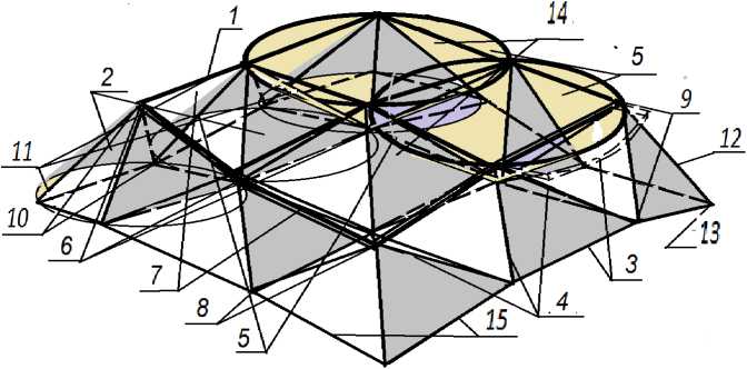
Fig. 1 — Fragment of the structural coverage block: 1 — spatial block of the structural coverage; 2 — hollow polygonal pyramids; 3 — the base of the pyramids; 4 — the edges of the pyramids; 5 — cones in which the pyramids are inscribed; 6 — the tops of the pyramids; 7 — panels in the upper bases of the pyramids (the cones are highlighted in color); 8 — details of connections; 9 — nodes of connection of pyramids; 10 — docking units; 11 —docking elements; 12 — supporting elements; 13 — support nodes; 14 — upper and 15 — lower belts
Innovative constructive and technological forms of structural and spatial coatings should ensure the implementation of all the above principles and approaches already at the stage of geometric cutting of the simplest surface in the form of a sphere. In this paper, several constructive and technological methods of forming structures on the simplest surface in the form of a sphere with quadrangular flat panels in the coating called the "Antants" system are proposed and investigated" [11], [12], [13], [14].
-
2 Methods and Materials
The essence of the proposed versions of the Antants sections is that the upper and lower belts are prefabricated spherical shells composed of flat quadrangular panels. At the common apex of the sphere, when divided into flat panels, there is a regular quadrangle (square panel), and the lower belt consists of hollow flat bases of solid or through pyramids. The upper and lower belts are built based on the Chebyshev network on a sphere with 90 ° sectors. This mesh gives the sphere the same properties as a spherical structure constructed by cones for an arbitrary surface (Fig. 1). The fact that not all surfaces on which Chebyshev networks are implemented can be represented by flat panels using cones is shown below (Fig. 6). Examples of the formation of spherical structures, verified by analytical methods using the proposed simplified mathematical models, are shown in Figures 2-4.
Figure 2 shows a spatial block of structural coating from reinforced cement hollow quadrangular pyramids and panels with supporting elements in perspective [3], [8], [15], [16].For the second variant of solutions within sectors of 90°, in prefabricated spherical shells of chords, quadrangular panels are made of frame and with corners described by circles of the same radius from the centers of the panels lying on the sphere [4], [17], [18].
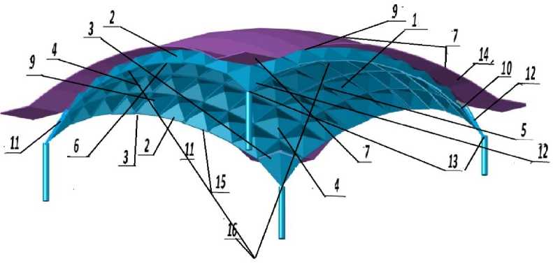
Fig. 2 — Reinforced cement spatial structure with docking panels in the upper belt: 1 —- spatial block of the structural coating; 2 — hollow polygonal pyramids; 3 — the base of the pyramids; 4 — the edges of the pyramids; 5 — cones in which the pyramids are inscribed; 6 — the tops of the pyramids; 7— panels in the upper bases of the pyramids (the cones are highlighted by filling); 8 — details of connections; 9 — nodes of connection of pyramids; 10 — docking units; 11 — docking elements; 12 — supporting elements; 13 — support nodes; 14 — upper and 15 — lower chords, 16 — center of spheres
Figure 3 shows a perspective view of a four-sector structure in a plan view of 90°. The space block shown here can be made so that the pyramids with top and bottom apexes are framed and form belts in spherical surfaces with a single center. For a better distribution of forces in the supporting elements of the blocks, the flat bases of the pyramids of the lower chord are constructed by planes from the points of the support nodes, which are located on the corresponding spherical surface of the chord and are made with ribs of different lengths (i.e., they are inscribed in indirect cones) [5], [19], [20]. The connecting elements are pyramids of blocks made with edges of the same length and a flat base in the adjacent part of the upper chord, which means that the proposed geometric schemes for dividing the spherical structure can be developed using the Chebyshev network as the initial basis for the formation, blocking, and organization of volumetric and expressive forms of transverse coatings [6], [21], [24].
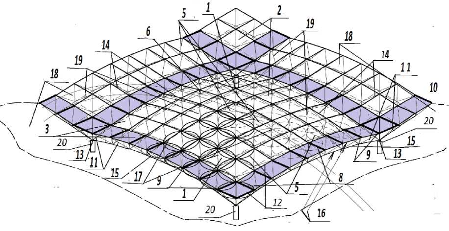
Fig. 3 — Fragment of the spatial block of the structural coverage of the building
Frame pyramids are made on enlarging stands and then stacked in a checkerboard pattern: first, one belt, then another. Enlarged and docking elements are stacked and connected in sectors or fragments of at least 1/8 of the block along the scaffolding, also from sectors with a certain geometry of the lower belt (Fig. 1) and with the possibility of turning or moving the scaffolding around the fixed central part [6], [21, [22].
In the third variant of solutions, structural coverings are also made of flat frame quadrangular panels, inscribed, but with a convexity downward (see Fig. 4). Figure 4 shows a perspective view from below of a structural covering with a bulge downward with consoles. Pyramids 2, with vertices six above and below, are made of frames from tubular rods 19 and form spherical surfaces with belts 14 and 15 with a center in the joining part 16 facing upward. In the concave parts of block 2, on the flat bases, 3 of the connecting elements-pyramids 17 of the lower chord, frame capitals 21 are made of tubular supporting elements-rods 12, on which they are mounted on the supports 20.
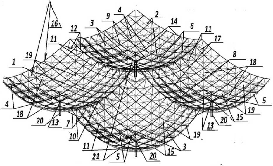
Fig. 4 — Spatial block of the structural covering of a building with concavities down
Figure 5 shows the node of the lower chord of the rod covered with rectangular tubular elements. Structurally, the spatial block can be made so that the pyramids and panels are made of the frame from rectangular tubular rods, the ends of which are flattened with a double bend and connected to incomplete pyramids of the lower chord and panels of the upper chord with tack weld [3], [12], [23].
Then, after assembling all the elements, they are welded in the tubular units by welding, using removable graphite clips, i.e., without a tubular outer cage left, into a finished structure with parts in the form of a left lining, protected with foam and a central cover or part for fastening the fence.
In comparison with the known solution, the proposed one allows for a reduction of the labor intensity of the coating as a whole to simplify the manufacture and installation by reducing the number of standard sizes of panels and elements, as well as reducing the number of jointed mounting elements, to perform a pre-assembly of structural elements; to increase the bearing capacity due to the effective outline of the coating and, accordingly, the reliability of the structure [4], [14], [24], [25].
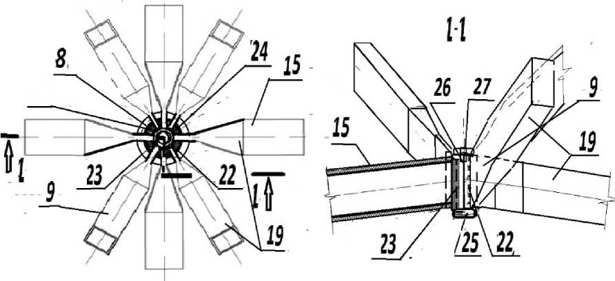
Fig. 5 — Nodes of the structure on tubular welding, flattened with a double bend of the ends of tubular rods
-
3 Results and Discussion
It also provides improved performance and architectural expressiveness of the structural coating. The position of the network, superimposed on the curved surface of the sphere, can be described by the set of coordinates of its nodes [5, 19, 28]. Imagine that in Euclidean space, the sphere's center is aligned with the origin. It is customary to orient the Chebyshev network on the surface so that the original directions of the threads are located along mutually orthogonal geodesic lines. The origin of the network - the center of coordinates is located at the zenith point, the coordinates of which are X = 0, Y = 0, Z = Ri. Here is the radius of the sphere of the upper belt. We combine the boundaries of the sectors with the directions of the meridians in the X0Z and Y0Z planes, which are geodesic lines on the sphere. The coordinates of the network nodes located on these meridians can be calculated using the formulas (1):
x i j = y i j = R i sin( i - 1) a ; z i j = R i cos( i — 1) a ; (1)
where i, j - are the ordinal numbers of the network nodes in the meridian directions along the X and Y axes, respectively, while at the zenith point, their values are equal to 1;
n a =------- - the value of the arc between the nodes of the network in radians; n is the number of
2( n - i)
Chebyshev network nodes on the axial meridian.
The task of calculating the coordinates of the network nodes on the sphere located between the axial meridians can be formulated as sequential finding the coordinates of the fourth nodes of spatially curvilinear equilateral quadrangles of the cells of the network using the known coordinates of two adjacent nodes. On a sphere, the equality of the lengths of the arcs also means the equality of their chords. Let us replace the consideration of a spatially curvilinear network cell with the study of its model Antoshkin, V.; Sagaidak, M; Dyugaev A.; Dixit, S.
Formation of spatial structural coverings;
as a broken spatial parallelogram. We can write down the compatibility requirement of two nonlinear equations for the required node as a point of intersection in the space of two segments of adjacent sides of a parallelogram (2).
(xi,j - xi-1,j )2 + (yi,j- y i-1,j)2 +(zi,j- zi-1,j)2
(xu — xi,j-i)2 +(У и — y,,j-1)2 +(zi,j — Zi,j-1)2- where h – chord is the shortest distance between adjacent nodes of a network cell. The formula easily calculates this distance:
-
h — 2R. sin a 1
The system solution (2) should be the equation of the circle as the line of intersection of two spheres of radius h with centers at the nodes adjacent to the desired one. The condition that the required knot lies on the sphere's surface can be written as an equation of a sphere of radius R (3).
x , j + у , j + Z i j — R 12 ;
This equation has two roots and determines that the required node can be located at one of the two points of intersection of the above circle with the sphere's surface. These points are two opposite vertices of a cell, the position of one of which is predetermined. Let us simplify system (2) by opening the brackets and considering that the sum of the squares of the coordinates of each node is equal to the square of the radius of the spherical surface centered at the origin of coordinates (4). We obtain a system of two linear equations (4):
k 1 xi,j + k2 У,, j + k3 — 0, t1 x, j + t2 zi, j + tз— 0; (4)
where, for simplicity, coefficients calculated by formulas (5) are introduced:
k 1 — Xi j + k 2 y i j + k 3 — 0;
t1 — xi-1j- У-1/1!k2- k2 — yi-1,jZi, j-1 - yi,j-1 Zi-1,j ;
t 2 — z i - 1, j - (5)
k 3 — (- - R 1 2)( z i , j - 1 - z i - 1, j );
t з — (y - R 1 2) - y i - 1, j k 3 / k 2 .
Rewriting equations (4) in the form of functions y i j — f ( x i j ); z i j — f ( x i j ); and substituting them into equation (3), we obtain a quadratic equation with one unknown (6):
zi j — f ( x i - , j );
, (6)
Ax,. ,2 + 2 Bx ,. + C — 0.
i,j i, J
Here, the coefficients A, B, and intercept C are introduced to simplify the notation and are calculated by formulas (7), considering (5).
k 1 2
A — 1 + + k22
B — k 1 k 3 / k 22
t 1 2
t 2 2 ;
+ 1 3 t i / 1 2 ;
c — k y + t y - R 2. k 2 2 t 2 21
Thus, to calculate the coordinates of the nodes of the Chebyshev network on the sphere, it is sufficient to find the larger of the roots of the equation x ij (6) and, substituting its value into equations (4), calculate the values of coordinates уц and zq . Note that in connection with the symmetry, it is sufficient to calculate the coordinates of half of the nodes since:
x. — x. ■ y. .
i , j j , i ; y i , j
- y. ■ z. . — z. ..
j , i i , j j , i
To form the upper belt with a radius R1 of a two-belt structure, it is necessary to use the values of coordinates with an even sum of indices while forming the lower belt with i + j — 2,4,6...2n, a radius R2 - with an odd sum of indices i + j — 3,5...2n -1.
Taking into account the restrictions given by cuts based on 90° sectors, we obtain for a span of 24 m an optimal cut on a sphere [5,29] with five rows of circles (see Fig. 4, 6), which consists of mounting only quadrangular panels of 9 standard sizes, for a span of 24 m or from five regular quadrangular panels, four irregular quadrangular panels and twelve triangular insert panels (for rods - a total of 35 standard sizes).
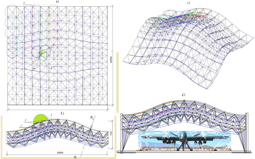
Fig. 6 — The structure of the spatial outline based on the transfer surface: a — 1 edge-radius of the intersection of three auxiliary spheres; 2 sides of the base of the pyramid; 3 spheres from the upper-level centers; 4 spheres from the centers of the lower level; 5 circles in which the bases of the pyramid are inscribed; b — 1-5 same as fig. 6, a, R1, R2 are the radii of curvature of the transfer surface of the upper level; c — without designations; d — the structure of the hangar cover for aircraft.
Transfer surfaces, tori, etc., are the simplest for forming structures using straight cones. Given that these surfaces can be represented by a repeating grid of guides or generators in the form of isosceles trapezoids, instead of splitting with straight cones, it is possible to use auxiliary spheres of the required radius to form equal braces-radii. Figure 6 a shows circle 5 describing the bases of the pyramids, as well Antoshkin, V.; Sagaidak, M; Dyugaev A.; Dixit, S.
Formation of spatial structural coverings;
as two auxiliary spheres, three centered at the nodes at the upper level and one sphere four at the node of the lower level [3, 29]. The intersection of the spheres forms a skew-radius 1 of the structure, and the planes of their intersection coincide with the faces of adjacent pyramids. In contrast to the structures on spherical surfaces, the structural load-bearing structure based on the transfer surface does not have radial symmetry. Still, due to the repeating grid of panels, it is more efficient and technologically more advanced than the spherical one. It has almost half the standard sizes of elements at the lower and upper levels at comparable coverage.
The above methods are the easiest way to solve the problem of constructing panel two-belt systems on transfer surfaces. However, these forms are used less often and require separate elaboration and research.
4 Conclusions
The following results were obtained in the study:
-
1. New methods and theories of their constructive and technological shaping have been developed
-
2. Components and connections of prefabricated elements have been developed on the basis of constructive solutions to ensure their safe operation.
-
3. Theoretically justified and implemented algorithms for the formation of a geometric triangular network on a sphere and the possibilities of other commonly used surfaces as a new structural and technological basis for structural structures.
Developed prefabricated spatial blocks of structural structures "Antants" can be used for coatings and enclosing elements of buildings for various purposes, as well as for the device of spherical reflectors in mirror antennas and energy concentrators.
The use of the indicated cones and circles for constructing a geometric network of flat quadrangles or pyramidal quadrangular elements with a flat base makes it possible to reduce the number of standard sizes of mounting elements of the dome by 5–30% to obtain, if necessary, flat quadrangular panels in the coatings, to ensure increased manufacturing accuracy during the enlarged assembly of coatings, and also take advantage of the design advantages of prestressing.
The designs based on the transfer surface and the main advantages are analyzed. It is more efficient and technologically more advanced than the spherical one. It has almost half the standard sizes of elements at the lower and upper levels at comparable coverage.
-
5 Conflict of Interests
Sponsors played no role in the study's design, collection, analysis, or interpretation of data, writing the manuscript, or deciding whether to publish the results. The authors developed the main mathematical approaches at the stage of geometric formation of surfaces in the form of structures on an initiative basis and presented them for the first time.
References Formation of spatial structural coverings
- Faibishenko V.K. (2015) Spatial framework of buildings and structures, including the nodal connection of the rods of the markhi system. Рatent RU 2 577 339 C1. https://patenton.ru/patent/RU2577339C1/en
- Nelasov V. S, Faibishenko V. K. Collapsible multi-level car parking. Patent RU 144543 U1 2013. https://rusneb.ru/catalog/000224_000128_0000144543_20140827_U1_RU
- Antoshkin V.D., Gorina M.V., Matyakubov H. (2021) Prospective structural and technological solutions of spatial structural coatings. Privolzhsky scientific journal, N. Novgorod. 2(58) 71–83. https://elibrary.ru/item.asp?id=46314125
- Antoshkin V.D., Travush V.I., Konovalov A.G., Erofeeva I.V. (2017) Composite block of prefabricated structural coating. Invention patent RU 2625582 C1. https://elibrary.ru/item.asp?id=38267720
- Udler E. M. (2014) Chebyshev grid on the surface of the sphere. International Journal of Applied and Fundamental Research, 6, 43–44. https://applied- research.ru/ru/article/view?id=5164&ysclid=lt2s1yzk92820403538
- Ishanova V.I., Shpikerman E.E., Udler E.M. (2013), Chebyshev network construction on the surface of a hyperbolic paraboloid. Izvestiya KGASU, 4(26),10–18. https://cyberleninka.ru/article/n/postroenie-seti-chebysheva-na-poverhnosti-giperbolicheskogo-paraboloida
- Antoshkin V. D. (2022) Prefabricated spherical shells with hexagonal panels based on the Chebyshev network. The privolzhsky scientific journal. 3 (63) Nizhny Novgorod, NNGASU,.22–36. https://pnj.nngasu.ru/word/articles/3-2022/3.pdf.
- Kudryavtseva, V. I., Udler E. M. (2015) On the formation of tent tent shells and the construction of shortest lines on the surface of negative. Gaussian curvature obtained by rotation of the generator. 5 (2). 309–312. https://fundamental-research.ru/ru/article/view?id=38213
- Vedyakov I. I. Pogoreltsev A.A., Pyatikrestovsky K.P. (2015) Prospects for improving the standards of designing wooden structures. Industrial and civil engineering, 4. 28–32. https://elibrary.ru/item.asp?id=23300577
- Udler E.M. (2012) Numerical method for calculating a soft shell filled with liquid and gas. Izvestiya KGASU. 2(20). 98–99. https://cyberleninka.ru/article/n/chislennyy-metod-rascheta-myagkoy-obolochki-zapolnennoy-zhidkostyu-i-gazom.
- Antoshkin V. D. (2017) Research of settlement models of the bearing framework with a compound spherical structural covering, Academia Architecture and construction. 1. 133-138. https://elibrary.ru/item.asp?id=29093264
- Popov, E. V. (1999) Cutting pattern generation for tent type structures. The Transactions of the Canadian Society for Mechanical Engineering. 22, 4, 253–261. https://www.semanticscholar.org/paper/CUTTING-PATTERN-GENERATION-FOR-TENT-TYPE-STRUCTURES-Popov/403f3b9171b60d80ade1f39cef70d466f1f72cf8
- Mishchenko A.V., Nemirovsky Yu.V. (2007) Calculation and design of wooden rod systems taking into account physical nonlinearity. Construction mechanics and calculation of structures. 6, 46 – 52. https://elibrary.ru/item.asp?id=22662689
- Pyatikrestovsky K.P., Travush V. I. (2015) On programming a nonlinear method for calculating wooden structures. Academia. Architecture and construction. 2, 115–119. https://cyberleninka.ru/article/n/o-programmirovanii-nelineynogo-metoda-rascheta-derevyannyh-konstruktsiy
- Suprun A.N., Dyskin L.M., Platov A.Yu., Lakhov A.Ya. (2012) Computer-aided design and strength calculation of single-contour geodesic shells made of flat elements. Bulletin of MGSU. 8, 226–233. https://elibrary.ru/item.asp?id=20599931
- Antoshkin V. D., Travush V.I., Gorina M. V., Antoshkin D. V., Konovalov A. G., Sagaidak M. O. (2019) Spherical shell with a coating. Patent for invention RU 2685602 C1. https://elibrary.ru/item.asp?id=38145206
- Fridkin, V. M. (2011) Shaping of building structures [Electronic resource. Moscow State University of Civil Engineering, EBS DIA, 171p. http://www.iprbookshop.ru/16318.html.
- Shirokov V. S. (2013) The search for optimal ratios of the boom of lifting and span of a structural dome structure. Bulletin of MGSU. 9. 32–40. https://cyberleninka.ru/article/n/poisk-optimalnyh-sootnosheniy-strely-podema-i-proleta-strukturnoy-kupolnoy-konstruktsii
- Udler E. M., Tolstov E. V. (2020). Method of fabricating covers of tent hypar roofs. Patent RU 2 728 063 C1 https://patenton.ru/patent/RU2728063C1
- Travush V.I., Antoshkin V.D., Erofeeva I.V., Antoshkin D.V. (2014) Assembled sperical shell. Patent for invention RU 2564545 C1. https://patenton.ru/patent/RU2564545C1/en
- Klyuev S.V., Klyuev A.V., Petrov N.I., Promahov V.V., Klimenko V.A. (2020) Optimal designing of the rod structure. International Journal of Engineering Research and Technology. 13, 11, 3757–3760. https://ripublication.com/irph/ijert20/ijertv13n11_95.pdf
- Lienhard W. (2011) Cyclic polygons in non-Euclidean geometry. Elem. math, 66, 2, 74-82. https://www.researchgate.net/publication/268017395
- Huybers P. (2002) Reciprocal polyhedra. Lightweight structures in civil engineering. Proceedings of the international symposium. Warsaw, Poland, 24, 28–29 https://research.tudelft.nl/en/publications/reciprocal-polyhedra
- Çarbaş S., Saka M.P. (2009) Optimum design of single layer network domes using harmony search method. Asian journal of civil engineering (building and housing. 10, 1, 97–112. https://www.researchgate.net/publication/241767744_
- Popov, E. V. Geometric Approach to Chebyshev Net Generation Along an Arbitrary Surface Represented by NURBS [Electronic resource] Proceedings of the International Conference on Computer Graphics & Vision GRAPHICON' 2002. Nizhny Novgorod https://www.graphicon.ru/html/2002/pdf/Popov_En_Re.pdf
- Behzad A., Hamid M., Amran A. (2012) Find the optimum shape design of externally pressurized torispherical dome ends based on buckling pressure by using imperialist Competitive Algorithm and Genetic Algorithm. Applied Mechanics and Materials Vols. 110—116. 956–964. https://www.scientific.net/AMM.110-116.956
- Wang, C. L. (2004). On increasing the developability of a trimmed NURBS surfaces. Computer-Aided Design. 1,.20 p. https://link.springer.com/article/10.1007/s00366-004-0272-8
- Lewis, W.J. Tension Structures: Form and Behavior. Kent: ICE Publishing, 2017. 210 p. https://www.researchgate.net/publication/268416833.
- Forster B., Mollaert M. European design Guide for tensile surface structures. Leonberg: Germany, 2004. 354 p. https://researchportal.vub.be/en/publications/european-design-guide-for-tensile-surface-structures
