Fractal multiband microstrip patch antenna for wireless applications

Author: Nilima Arun Bodhaye, P.L.Zade
Journal: International Journal of Wireless and Microwave Technologies @ijwmt
Article in issue: 5 Vol.8, 2018.
Free access
This paper proposes a design of fractal multi-band microstrip patch antenna dedicated for wireless applications. The proposed antenna uses a FR-4 epoxy substrate having permittivity 4.4 and tangent loss to be 0.02.The microstrip antenna proposed is designed by incorporating double I-shape slot on the surface of rectangular patch and simulated by using HFSS software. Further the antenna is modified by inserting fractal shape and obtained the three frequency bands located at 2.4Ghz , 3.5Ghz and 5.50Ghz respectively and antenna parameter like VSWR, return loss, antenna gain, directivity of an antenna and bandwidth has been analyzed. The designing of proposed antenna is to be followed by fabrication by using A FR-4 substrate of thickness 1.60mm. Further, this paper discusses, the simulated and measured results comparison and analysis of the same. For designing and simulating of antennae simulation software HFSS has been used. The simulated and measured results represented are in permissible range.
Fractal, microstrip, HFSS, return loss, VSWR, multi-band
Short address: https://sciup.org/15016945
IDR: 15016945 | DOI: 10.5815/ijwmt.2018.05.05
Text of the scientific article Fractal multiband microstrip patch antenna for wireless applications
In a massively developing technical world many recent devices used in government and commercial purpose have similar specifications for dedicated applications such as mobile radio, wireless communication etc[1]. In order to meet variety of requirements, printed microstrip antennas can be preferably used [1].The reason behind the popularity of microstrip antennas is being the low profile, effective adaptability to planer and non-planar surfaces, mechanically robust when mounted on rigid surfaces, simple yet inexpensive for manufacturing used
* Corresponding author. Tel.:
in modern printed circuit technology, very nice compatibility with MMIC designs. Also when the particular shape of the patch and mode are chosen, they are found to be pretty good versatile in context of parameters like resonant frequency, polarization, radiation pattern and impedance matching[1].
Emerging trends in the development of domains such as wideband antennas, multi-band antennas or re-configurable antennas are grabbing much attention as they have capability to fulfils variety of specifications of different applications only in one single terminal. Such single terminals or devices provides many applications as WLAN,GPS, GSM, Bluetooth and many more. To meet these different applications wide-band, multi-band or re-configurable antennas have been emerged [1].A dual band microstrip patch antenna with good gain and efficiency for resonance frequencies 2.45 Ghz and 4.41 Ghz is applicable for the applications of RADAR, Bluetooth and Biomedical instrumentation[2]. To achieve Multi resonant structure current distribution is disturbed intentionally by incorporating slot of the appropriate dimension on to the surface of either on microstrip ground plane or on the surface of the microstrip patch. Some of the slot structures like defective ground structure and fractal slots has attracted the designer by their different features such as for size reduction, bandwidth enhancement, co-polarization enhancement and depressing cross-polarization and many more. A novel approach by designing antenna with the open eye shaped slot in circular patch which is embedded inside a rectangular slot of a rectangular microstrip patch has been proposed to achieve multi-band antenna for smart grid and ultra wideband (UWB ) applications[3].80% of size reduction along with the multi band characteristic is achieved for wireless and satellite communication by simply indulging array of rectangular slits on not radiating edges[4]. However truncating of the patch at the four corners of patch also has been proved to be very effective to achieve triband as well as dual polarization feature for WIMAX, WLAN and GSM/DCS applications [5]. DGS structure is used to achieve multi-band and size reduction as well. A compact rectangular microstrip patch antenna having triangular slots in ground plane has been designed for Wireless Local Area Network, Worldwide interoperability for microwave access(WI-MAX), Airport surveillance and Direct broadcast satellite(DSB) Europe [6].To reduce the mutual coupling DGS technique is adopted. To enhance the isolation between the closely placed antenna with inserting DGS and microstrip matching network. By introducing DGS, the distribution of ground surface current and is varied and mutual coupling caused by near field is decreased[7]. Fractal shapes are utilized in antenna design to improve its parameters. Nobel enhancement of gain and directivity obtained from fractal antenna also the bandwidth of negative refractive index is increased when extra spaces are used in antenna design [8]. A E-shaped fractal antenna with two iterations has been developed along with incorporating DGS structure to meet the specification of wireless applications [9]. For the Fractal shapes like Sipernski Gasket, Minkowski, Hilbert Curve and Koch Curve, Fractal Arrays can be applied on multiband antenna so as to reduce antenna size. A dual polarized microstrip Sipernski fractral patch was designed with two iterations for S band[10]. A triband circularly polarized boundary microstip antenna was perturbed with asymmetrical kochfractal curves at the boundaries to achieve 3dB axial ratio bandwidth for WLAN and WIMAX applications was represented [11]. Other fractal shape such as Hilbert fractal slot introduced inside a rectangular microstrip patch is useful to generate multi resonating frequencies and act as additional resonator along with microstrip feed line, thereby achieving almost bidirectional radiation pattern at all operating frequencies covering wireless applications[12].By introducing parallel slot , size reduction has been achieved and resulted in mild changes in resonance frequency along with constant gain and as a length of slot increased. There is comparatively less variation in the gain[13]. In order to accomplish miniaturized antenna structure various techniques has been developed. By using high dielectric constant of range 10.2 permeabilities has found to be useful for miniaturizing the multi-band antenna for ISM ,WIMAX and Wi-Fi application[14].
This paper proposes a fractal design of multi-band microstrip patch antenna having defected ground structure in ground plane by using substrate material as FR-4 epoxy material and multiple resonating frequencies are obtained by cutting double I-shape slots on the radiating patch, defective ground structures are used for impedance matching. The propose work of the antenna is featured for three applications as Wi-Fi, WiMAX and Blue tooth. Section 1.1presents the Design structure of the proposed multi-band antenna, Section1.2 explains the result and discussion. Section 1.3 presents the result and discussion. Finally, the paper has been concluded in 1.4. On the basis of parametric study slots have been incorporated on the surface of microstrip patch so as to generate multiple resonant frequency bands.
-
1.1. Structure
-
1.1.1 Rectangular patch antenna at 2.4 GHz design
-
In this section the basic simple rectangular microstrip patch antenna design has been described. The three important parameters necessary for the designing rectangular microstrip Patch Antenna are:
-
• Operating frequency (fo): The prime step is to select the operating frequency of the antenna appropriately in accordance with application. 2.4 GHz has been chosen to be resonant frequency.
-
• Dielectric for the substrate (εr): for the substrate FR4 glass epoxy has been used as a dielectric material having permittivity constant 4.4.
-
• Dielectric substrate height (h): Height of the substrate is the very important parameter for microstrip patch antenna to be used in wireless applications, essentially antenna should not bulkily. Hence, the height of the dielectric substrate is chosen to be 1.6 mm. Table 1 below shows the calculated values of the parameter.
Table 1.Dimensions of the Antenna Structure
|
S.N. |
Parameter |
Dimensions (m.m.) |
|
1. |
Width of patch W |
38.22 |
|
2. |
Effective dielectric constant εreff |
3.99 |
|
3. |
Length of patch L |
30.25 |
|
4. |
Substrate Length Ls |
59 |
|
5. |
Width of the substrate Ws |
50 |
|
6. |
Feed length |
14.5 |
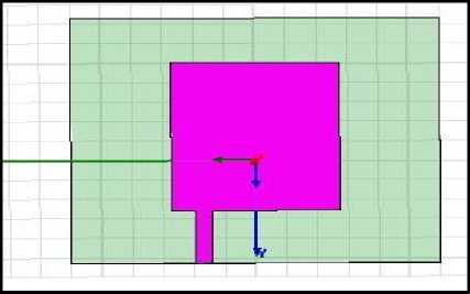
Fig.1.1. design of simple rectangular microstrip patch antenna
(a)
(b)
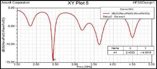
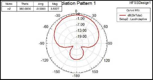
Fig.1.2. (a) s11 parameter of rectangular microstrip patch antenna (b) radiation pattern of RMSA
The simple rectangular microstrip patch antenna has been designed by calculating the basic antenna parameter and also observed the s11 parameter and radiation pattern using High frequency simulation software. Figure 1.1 (a) depicts the return loss of the rectangular microstrip patch antenna at 2.43 Ghz below -10 dB i.e.-14.60 dB and figure 1.1 (b) depicts the graphical representation of radiation pattern of simple microstrip patch antenna.
-
1.2. Design of fractal Multi-band Microstrip Patch Antenna
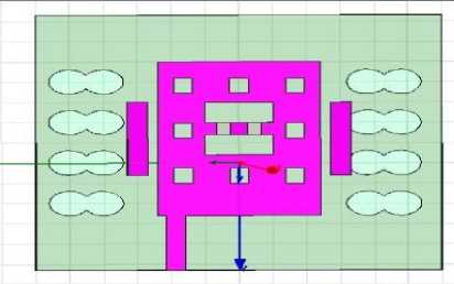
Furthermore, to obtain the multi-band frequencies, a simple structure of rectangular microstrip patch antenna for 2.4 Ghz , is modified by cutting double I-shape slot on the radiating patch and incorporating dumbbell shape defective ground structure. To obtain multiple resonant frequencies no of slots have been incorporated on the basis of parametric studies in the microstrip patch. The defective ground structure is used to increase the effective length of the antenna, thereby reducing the physical length of resonance [1].The proposed fractal Multi-band microstrip patch antenna is designed in three steps. Initially, in order to obtain the multiple frequency bands, the double I-shape slot is inserted on the radiating patch. Two parasitic elements parallel to the radiating patch have been embedded to perturb the surface current path; also local inductive effect has been introduced to obtain multi-band frequency operation.
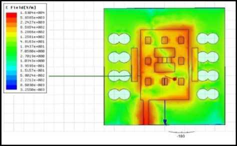
Fig.1.3 (a) shows the design of proposed microstrip patch antenna which incorporate fractal geometry along with the defected ground structure. In this paper, dumbbell shape DGS has been used. Fig. 1.3 (b) shows the current distribution plot for the proposed antenna.
(a)
(b)
Fig.1.3. (a) Design of proposed microstrip patch antenna (b) Current distribution of the proposed antenna
-
1.3. Simulations and Result
The verification and analysis of this antenna have to be carried out so as to achieve the desired results. The simulating and optimizing the proposed microstrip patch antenna has been carried out by frequency EM solver simulation software (HFSS). Fig 1.4 (a) and (b) depict the simulated return loss and VSWR for the same of the proposed antenna are as below.
(a)
(b)
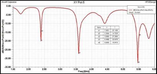
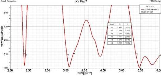
Fig.1.4. (a) s11 parameter of fractal antenna (b) VSWR of fractal antenna
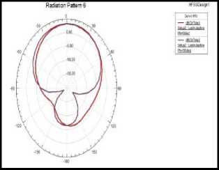
The resonant frequencies for the simulation results are lies at 2.40Ghz, 3.58Ghz and 5.50Ghz with reflection coefficient -20.14dB, -27.26 dB and -32.64 dB respectively. The resonant frequencies can be varied by adjusting and optimizing the dimensions of fractal geometry. The E-plane and H-plane radiation for the different three frequency bands are shown in Fig.(a), (b) and (c).
(a)
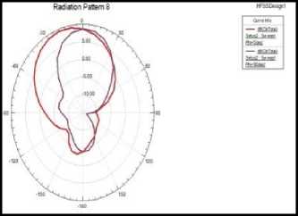
(b)
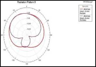
(c)
Fig. 1.5. E-plane and H-plane field (a) at 2.40Ghz (b) at 5.50Ghz frequency(c) at 3.58Ghz frequency
The antenna proposed has been fabricated followed by testing so as to verify the results of simulation .Fig.1.6(a) and Fig.1.6 (b) depict a fabricated antenna. However in table 2.A comparative analysis of measured and simulated results has been shown.
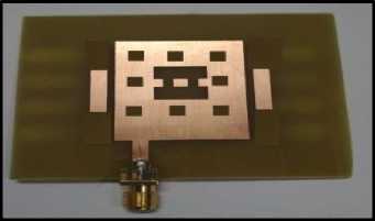
(a)
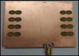
(b)
Fig.1.6. (a) front view of proposed fabricated antenna (b): back view of proposed fabricated antenna
(a)
(b)
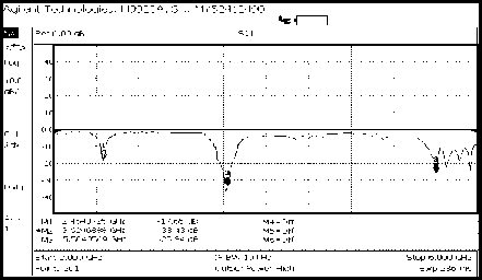
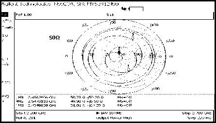
Fig.1.7. (a) Measured return loss antenna of proposed fabricated antenna (b) smith chart of proposed fabricated antenna
Fig.1.7(a) shows the measured return loss and fig (b) shows the measured impedance plot for the proposed fabricated antenna prototype. From table 2, It could be observed the measured and simulated results has permissible similarity.
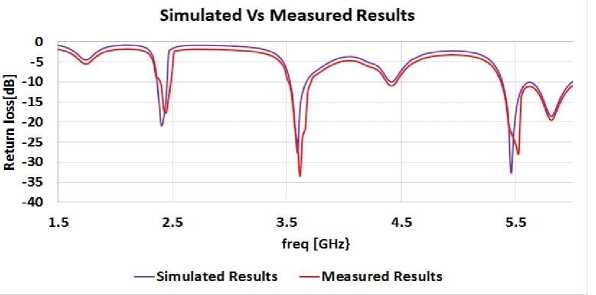
Fig.1.8. Simulated and Measured return loss plot of prototype of double I-slot RMSA with parasitic elements and DGS
Table 1. Comparison table Simulated Vs Measured Results of Fractal Antenna
|
Sr. No. |
Results |
Freq (GHz) |
Return loss(dB) |
VSWR |
Bandwidth (MHz) |
Impedance (ohm) |
|
1. |
Simulated results |
2.40 |
-20.14 |
1.21 |
60 |
50.8 |
|
3.58 |
-27.26 |
1.09 |
130 |
|||
|
5.50 |
-32.64 |
1.05 |
700 |
|||
|
2. |
Measured Results |
2.45 |
-17.65 |
1.32 |
64 |
50.7 |
|
3.62 |
-33.43 |
1.04 |
150 |
|||
|
5.50 |
-25.84 |
1.10 |
660 |
2. Conclusions
This paper deduces a fractal multi-band antenna resonating for three multiple frequency bands for wireless standards such as WI-FI, WiMAX and Bluetooth. The antenna proposed is fabricated and RF Vector Network Analyzer of Agilent technologies of series N9923A having range 300Khz to 8GHzhas been used to test the antenna for validation with simulation results. To reduce the reflections Defective ground structure has been introduced. However microstrip feed line has been used for matching the impedance. This antenna is dedicated to work for three wireless frequencies, which are 2.45GHz, 3.62 GHz and 5.50GHz.This proposed antenna can be further modified into re-configurable antenna by incorporating switches in the switch-able slots.
References Fractal multiband microstrip patch antenna for wireless applications
- Balanis, C.A. Antenna theory : Analysis and Design John Wile and Sons Inc New Jersy ,1997.
- Sheikh Dobir Hossain a , K. M. Abdus Sobahan b , Md. Khalid Hossain c* , Md. Masud Ahamed, “A Rectangular Microstrip Patch Antenna for Wireless Communications Operates in Dual Band”I.J. Wireless and Microwave Technologies, 2016, 5, 35-44.
- Akash d , Rebeka Sultana e , Md. Masum Billah fKirtiVyas, A. K. Sharma, P. K. Singhal, “3A Novel CPW Fed Multiband Circular Microstrip Patch Antenna for Wireless Applications”, 2012 Fourth International Conference on Computational Intelligence and Communication Networks,978-0-7695-4850, IEEE,2012, pp. 1-4.
- Pristin K Mathew, S. Merlin Gilbert Raj, UjwalPrakash A.J, “Compact Multiband Antenna for Wireless and Satellite Communication”,2014 ,ICECS -2014, International Conference on Electronics and Communication Systems, 13 -14 February 2014.
- Rahul S. Parbat , Sagar D. Mahamine, Shekhar H. Bodake, Mahesh P. Aher, “Dual Polarized Triple Band Microstrip Antenna for GSM/WiMAX/WLAN Applications”, 2016 International Conference on Automatic Control and Dynamic Optimization Techniques (ICACDOT) International Institute of Information Technology (I²IT), Pune,978-1-5090-2080-5, IEEE, 2016, pp.1137-1141.
- Amiya B. Sahoo, AyushBiswal, Chandan K. Sahu, Jogesh C. Dash, B. B. Mangaraj, “Design of Multi-band Rectangular Patch Antennas using Defected Ground Structure (DGS)”, (RTEICT), IEEE International Conference On Recent Trends in Electronics Information & Communication Technology, India, 978-1-5090-3704-9, pp.1183-1187, 19-20 May 2017.
- Sachin S. Khade, S.L.Badjate , “A Compact Multiband U Shape MIMO Antenna for Wireless Application”I.J. Wireless and Microwave Technologies, 2016, 5, 61-71.
- Ammar Nadal Shareef, Amer Basim Shaalan, “Fractal Peano Antenna Covered by Two Layers of Modified Ring Resonator”
- Ajay Nagpal, A. Marwaha, “Multiband E-shaped fractal microstrip patch antenna with DGS for wireless applications,”2013 5th international conference on computational intelligence and communication networks, 2013
- Ms. Ali Fathima N. A.,Ms. Jayarenjini N, Ms. Megha S., Dr. Unni C.,” Dual Polarized Microstrip Fractal Patch Antennfor S-band Applications, ICCC, 2015, International Conference on Control, Communication & Computing India, Trivandrum ,978-1-4673-7349-4,19-21, November 2015, pp.464-469
- V.V.Reddy,N.V.S.N.Sarma,”Triband Circularly Polarized Koch FractalBoundary Microstrip Antenna,” IEEE ANTENNAS AND WIRELESS PROPAGATION LETTERS, VOL. 13, 2014, pp. 1057-1060
- ChamaipornRatnaratorn, NorakamonWongsin, ChatreeMahatthanajatuphat, Prayoot, Akkaraekthalin ,”A Multiband Wide Slotted Antenna with Hilbert Fractal Slot on Rectangular Patch,”978-1-4799-0545-4, IEEE.
- Deepanshu Kaushal , Shanmuganantham Thangavelu, “Design of Microstrip Trapezoidal Patch Antenna Using Coaxial Feeding Technique for Space Applications” I.J. Wireless and Microwave Technologies, 2017, 6, 1-12.
- Amal K A, Subin Joseph, Sree kumara amma, Ajoy kumar Mondal, R.Ratheesh, ”Compact Multiband Microstrip Patch Antenna For Wireless Applications,”2016 International Conference on Communication Systems and Networks (ComNet) ,IEEE, 978-1-5090-3349-2, 21-23 July 2016, pp.153-156.
