Fuzzy Logic Control of Wind Turbine System Connection to PM Synchronous Generator for Maximum Power Point Tracking

Author: Hadi Sefidgar, S. Asghar Gholamian
Journal: International Journal of Intelligent Systems and Applications(IJISA) @ijisa
Article in issue: 7 vol.6, 2014.
Free access
In this paper, a fuzzy logic control (FLC) is proposed for maximum power point tracking (MPPT) in wind turbine connection to Permanent Magnet Synchronous Generator (PMSG). The proposed fuzzy logic controller tracks the maximum power point (MPP) by measurements the load voltage and current. This controller calculates the load power and sent through the fuzzy logic system. The main goal of this paper is design of the fuzzy logic controller in the model of DC-DC converter (boost converter). This method allows the MPPT controller output (duty cycle) adjusts the voltage input to the converter to track the maximum power point of the wind generator.
Wind Turbine, Fuzzy Logic, PMSG, MPPT
Short address: https://sciup.org/15010579
IDR: 15010579
Text of the scientific article Fuzzy Logic Control of Wind Turbine System Connection to PM Synchronous Generator for Maximum Power Point Tracking
Published Online June 2014 in MECS
Nowadays Renewable energy is developed because of the environmental problems and fossil-fuel exhaustion. Compared with another renewable energy such as solar energy, although wind energy systems are to the smaller extent costly to install than the solar system, however, the use of power electronic converts will be to a lesser degree extent [1].
The power generation using wind energy is possible in two ways, constant speed operation and variable speed operation using power electronic converts. The variable speed operation for wind generator is attractive because of its characteristic to achieve maximum efficiency at all wind velocities. Therefore, variable-speed control of the permanent magnet synchronous generator (PMSG) that applied vector control is needed [2].
Among different types of wind turbine, permanentmagnet (PM) generator is widely used because of its high reliability and simple structure, especially for small-size wind turbines [4-5].
The wind systems are, by nature, non-linear power sources that need accurate on-line identification on the optimal operating point. Thus, to achieve optimal point requires a MPPT controller. MPPT controller changes the rotor speed according to the variation of wind speed so that the tip speed ratio (TSR) is optimal [3].
One of the ways to achieve the maximum power point, this is a turbine blade pitch angle (β) can be controlled but for a low-power wind turbines, blade pitch angle control method is impossible, due to mechanical problems in its construction. Therefore, to achieve maximum power at low power turbine must be used the power control methods [6]. Now, the maximum power tracking control methods commonly used are tip-speed ratio control (TSR), optimal torque control (OT) [7] ,power signal feedback (PSF) [8] and search control method [9]. The TSR, OT and PSF are a costly method, due to mechanical sensors. But the search control method does not require a mechanical sensor. Also, this method is independent of the characteristics of the turbine and generator. Another benefit of this method is simple structure and high reliability [10]. However, for small and stand-alone wind power systems, the simplicity and reliability of the power controller is very important. In this paper presents a new MPPT control strategy which predicts the maximum power point make use of fuzzy logic without mechanical sensors.
-
II. Wind Turbine Modeling
If you can ignore the friction of the rotor, turbine mechanical properties can be expressed by the following equations [11]:
Tm - Toad = Jd!(1)
dt
Pm — PLoad = J®^
dt
Pm = 0.5 X Cp (X, в) x px A X V3(3)
X = (Rm®) ^ V(4)
Where Tm is shaft mechanical torque, Tload is electromagnetic torque; J is combined inertia of rotor and load. Pm is mechanical output power of the turbine (w), ρ is air density (kg/m3), a is turbine swept area (m2), v is wind speed (m/s), Cp(λ,β) is performance coefficient of the turbine, β is blade pitch angle (deg), Rm is turbine radii(m), ωm is turbine angular velocity (rad/s) and λ is tip speed ratio of the rotor blade tip speed to wind speed.
The mechanical power generated by the turbine rotor to the initial power of the wind turbine power coefficient (Cp) say that a non-linear relationship between the tip different blade angle, the power coefficients vary with tip speed ratio.
From figure.1, we can see the variation of power coefficient versus the blade pitch angle β. Where the β gradually increases, the curve of Cp will decrease significantly. Generally, to achieve the maximum wind power, β value should be very small. If β is at a given
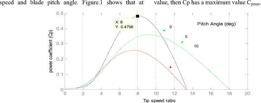
Fig.1. Wind-turbine power coefficient characteristics of a wind turbine.
In this paper, the value of β is equal to zero and power coefficient only function of tip speed ratio is considered. According to equation 3, the most important parameters to achieve the maximum power point wind turbine is Cp curve, so that maximum power output of wind turbines occurs when cp is maximum. The constant β, the optimum Cp occurs at different values of λ. Determined for each wind speed, there is an optimum rotor speed as the wind speed, and the power output is maximum. So if the wind speed is considered constant, Cp value will depend on the wind turbine rotor speed. Thus, by controlling the rotor speed, turbine power output is controlled. In addition, for each specific wind speed, there is only one rotor speed which leads to maximum power
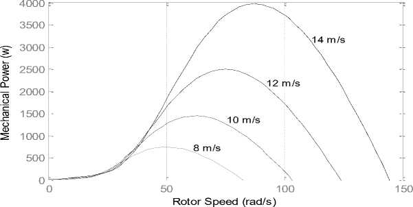
Fig. 2. The power curves for different wind speeds and zero bitch angle
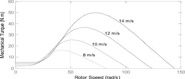
Fig. 3. the Torque curves for different wind speeds and zero bitch angle
Figures 2 and 3 show the curves of the wind turbine power- rotor speed and turbine torque – rotor speed for the different wind speeds. From the figures, it is clear that for the different power curves, the maximum powers are achieved at the different rotor speeds. Therefore, the rotor speed should be operated at the optimum speed. This technique is called as MPPT (Maximum Power Point Tracking).
-
III. Maximum power point control
Figure4 presents the block diagram of the wind energy conversion system in our research; wind energy by wind turbines is converted into mechanical power on the shaft. Mechanical power by a permanent magnet synchronous generator (PMSG) is converted into electrical power.
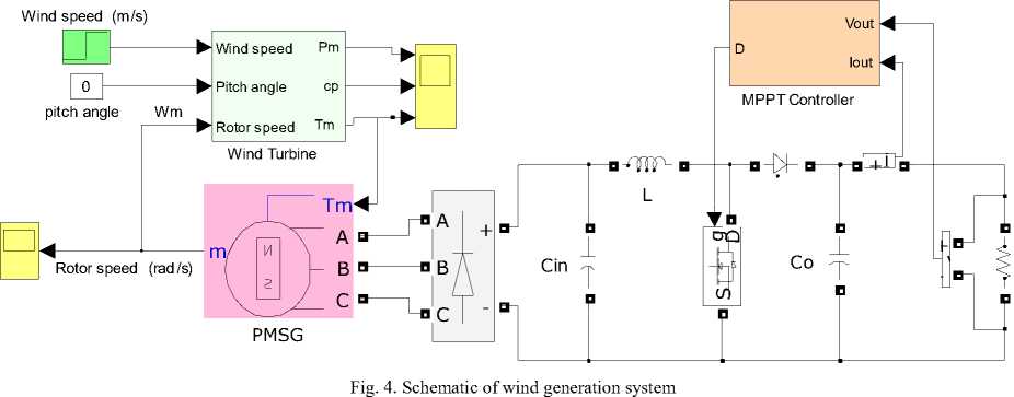
The generator ac output voltage is converted to dc form using a three-phase full-wave bridge rectifier. The main purpose of applying the rectifier, isolation voltage variable frequency produced by the machine, the load must operate at a fixed frequency, it is.
The boost DC / DC converter to control the output voltage of the rectifier (V dc ) is applied. Rectifier output voltage and current are measured and sent to the controller.
-
IV. Fuzzy algorithm to achieve MPPT
In references [12-13] , a new approach was proposed for tracking control of maximum power which is independent of the characteristics of the turbine.
In this methodology, the controller measured voltage and current of the rectifier then, search the maximum power point.
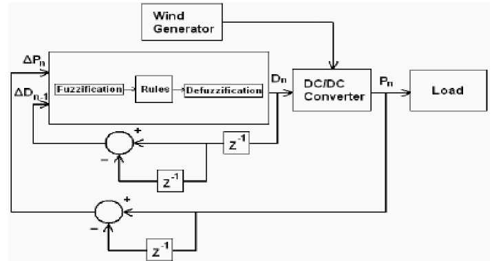
Fig. 5. Block diagram of the fuzzy controller
In this paper, the fuzzy algorithm used to achieve the maximum power point. In this methodology, the load voltage and current measurements and output power is calculated and sent to the controller. Fig. 5 shown the block diagram of the controller used in this case.
During the process of fuzzy membership functions with a range of 0 and 1 is used to convert the controller’s input variables to membership values ranging. For the FLC used, membership functions are chosen to be of triangular form for reasons of simplicity since they are less demanding in computational resources. Two inputs for the FLC are the output power variation, ΔPn and the converter’s output duty cycle difference, ΔDn-1.
kF =р -nn
Pn - 1
io n n-1
o n-2
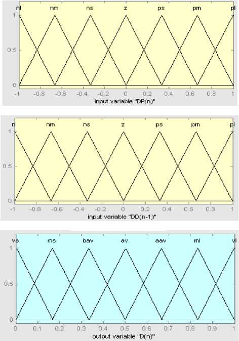
Fig. 6. Membership functions for fuzzy variables
For the fuzzy inference engine, “IF-THEN” rules with “AND” logical operators are designed for the fuzzy variable process. Table 1 displays the rules governing the controller’s operation. The system will measure the output power difference ΔPn and adjust D in order to track the MPP. Fig. 6 shows the membership functions for the inputs of ΔP , ΔDi and output Do , normalized in the range of [-1,1].
Table1. Fuzzy rules
|
Δ Di n |
Δ P n |
||||||
|
nl |
nm |
ns |
z |
ps |
pm |
pl |
|
|
nl |
vl |
vl |
ml |
bav |
ms |
vs |
vs |
|
nm |
vl |
ml |
aav |
bav |
bav |
ms |
vs |
|
ns |
ml |
aav |
aav |
av |
bav |
bav |
vs |
|
z |
vs |
ms |
bav |
av |
aav |
ml |
vl |
|
ps |
ms |
bav |
bav |
av |
aav |
aav |
ml |
|
pm |
vs |
ms |
bav |
aav |
aav |
ml |
vl |
|
pl |
vs |
vs |
ms |
ml |
ml |
vl |
vl |
ΔP = nm AND ΔDi n = nm , then a large duty cycle is commanded, i.e. Do = ml , to keep the system on the same course.
Defuzzification is the process through which the single output fuzzy set, deriving from the aggregation of the outputs of each rule, is converted to a single alue. Here, the centroid defuzzification method, which returns as output the centre of the area under the curve of the output fuzzy set, is used.
-
V. Simulation Results
The model of wind energy system with MPPT control is simulated using MATLAB/ SIMULINK as shown in Fig. 4. The wind energy system include: Wind Turbine, Permanent Magnet Synchronous Generator (PMSG), Three Phase Full Bridge Rectifier, Boost DC/DC Converter and MPPT Controller. Table 2 shows the parameters of the Wind Turbine and PMSG used in simulation model.
Table 2. The parameters of the wind turbine and PMSG
|
Turbine- Rated power |
2.5 |
kw |
|
Rated Wind Speed |
12 |
m/s |
|
Optimum power coefficient |
0.48 |
- |
|
PMSG- Rated power |
3 |
kw |
|
Ld, Lq |
0.435 |
mH |
|
P |
4 |
- |
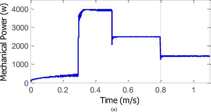
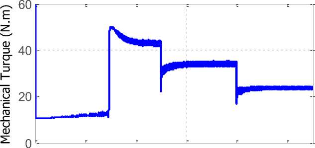
In this simulation, the wind speed has changed in three steps. Wind speed at time t 1 = 0.5s and t 2 = 0.8s is changed from 14 m/s to 12 m/s and then to 10 m/s is reduced. With the change of wind speed, the performance of wind turbine with fuzzy controller can track the maximum power delivery operating point .
Figure7 shows the variation of the wind speed and generator speed. It is seen that according to the wind speed variation the generator speed varies and that its output power is produced corresponding to the wind speed variation.
As was said, Turbine power coefficient is the most important parameters for optimum system performance and obtain the maximum power from the wind. Figure8 shows simulation results of the aerodynamic coefficient г p .
Figure8 displays that when the wind speed changes, the wind turbine power coefficient had small fluctuations phenomenon, but the value of the wind turbine power coefficient would back to the best value soon. It costs less then 0.2s from one stable state to another stable state.
The optimal power coefficient value 0.48. In figure 8, we can see the controller fast and accurate performance.
Figure9 shows the mechanical power and turbine torque curves.
If for example a medium power increase is measured having resulted from a previous duty cycle increase i.e.
0 0.2 0.4 0.6 0.8 1
Time (s) (a) wind speed
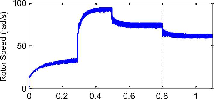
Time (s) (b) Rotor speed
Fig. 7. Simulation results of rotor speed for a step variation of wind speed.
Power Coefficient (Cp)
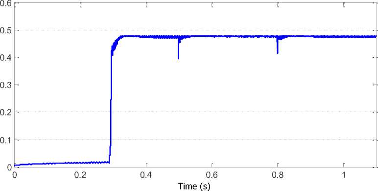
Fig. 8. Simulation results of aerodynamic constant Cp for three step variation of wind speed
0 0.2 0.4 0.6 0.8 1
Time (s)
(b)
Fig. 9. (a) the mechanical power and (b) turbine torque curves
-
VI. CONCLUSIONS
In this paper, we have proposed a fuzzy logic MPPT technique which can extract maximum power is described and verified through the simulation. The proposed method is completely independent of the properties of turbine and generator. This new MPPT doesn’t need the wind speed measurements but the voltage and current load is measured. So this method is not any mechanical sensor which will result in reduced costs and increased reliability of the system. Moreover this control strategy is comparatively easy, and has high practical value. Simulation results show that in any atmospheric conditions such as wind speed changes, the wind turbine system can run stable, and to track the maximum power.
References Fuzzy Logic Control of Wind Turbine System Connection to PM Synchronous Generator for Maximum Power Point Tracking
- Senjyu, T., Tamaki, S., Muhando, E., Urasaki, N., Kinjo, H., Funabashi, T., et al. (2006). Wind velocity and rotor position sensorless maximum power point tracking control for wind generation system. Renewable Energy, 31, 1764–1775.
- A. Meharrar; M. Tioursi, M. Hatti, A. Boudghène Stambouli." A variable speed wind generator maximum power tracking based on adaptative neuro-fuzzy inference system". Expert Systems with Applications 38 (2011) 7659–7664.
- J. F. Manwell, J. G. Mcgowan, A. L. Rogers, Wind Energy Explained: Theory, Design and Application, John Wiley & Sons Ltd, Chichester, 2002.
- C. H. Ng, M. A. Parker, R. Li, P. J. Tavner, J. R. Bumby, and E. Spooner, “A multilevel modular converter for a large, light weight wind turbine generator,” IEEE Trans. Power Electron., vol. 23, no. 3, pp. 1062–1074, May 2008.
- K. Protsenko and D. Xu, “Modeling and control of brushless doubly-fed induction generators in wind energy applications,” IEEE Trans. Power Electron., vol. 23, no. 3, pp. 1191–1197, May 2008.
- Kuo-Yuan Lo, Yaow-Ming Chen, Senior Member, IEEE, and Yung-Ruei Chang, Member, IEEE.' MPPT Battery Charger for Stand-Alone Wind Power System'. IEEE transactions on power electronics, vol. 26, no. 6, june 2011.
- S.Morimoto, H. Nakayama, M. Sanada, andY. Takeda, “Sensorless output maximization control for variablespeed wind generation system using IPMSG,” IEEE Trans. Ind. Appl., vol. 41, no. 1, pp. 60–67, Jan./Feb. 2005.
- K. Tan and S. Islam, “Optimum control strategies in energy conversion of PMSG wind turbine system without mechanical sensors,” IEEE Trans. Energy Convers., vol. 19, no. 2, pp. 392–399, Jun. 2004.
- C. Pan and Y. Juan, “Novel Sensorless MPPT Controller for a High-Efficiency Microscale Wind Power Generation System,” IEEE Trans. Energy Conversion. Vol 24, pp. 1-10, Jun. 2009.
- Kuo-Yuan Lo, Yung-Ruei Chang, and Yaw-Ming Chen, ''Battery Charger with MPPT Function for Stand-Alone Wind Turbines'', The 2010 International Power Electronics Conference.
- T. Tanaka, T. Toumiya, T. Suzuki, “Output control by hill climbing method for a small scale wind turbine generating system,” Renewable Energy, Vol. 12, No. 4, 1997, pp: 387- 400.
- E. Koutroulis, and K. Kalaitzakis, “Design of a maximum power tracking system for Wind-Energy-Conversion applications”, IEEE Trans.on Industrial Electronics, Vol. 53, no. 2, pp. 486-494, April 2006.
- N. Yamamura, M. Ishida, and T. Hori, “A simple wind power generating system with permanent magnet type synchronous generator”, IEEE International Conf. on Power Electronics and Drive Systems, PEDS ’99, Hong Kong , July 1999.
