Fuzzy Predictive Control of Step-Down DC-DC Converter Based on Hybrid System Approach

Author: Morteza Sarailoo, Zahra Rahmani, Behrooz Rezaie
Journal: International Journal of Intelligent Systems and Applications(IJISA) @ijisa
Article in issue: 2 vol.6, 2014.
Free access
In this paper, a fuzzy predictive control scheme is proposed for controlling output voltage of a step-down DC-DC converter in presence of disturbance and uncertainty. The DC-DC converter is considered as a hybrid system and modeled by Mixed Logical Dynamical modeling approach. The main objective of the paper is to design a Fuzzy Predictive Control to achieve desired voltage output without increasing complexity of the hybrid model of DC-DC converter in various conditions. A model predictive control is designed based on the hybrid model and applied to the system. Although the performance of the model predictive control method is satisfactory in normal condition, it suffers from lack of robustness in presence of disturbance and uncertainty. So, to succeed in facing up to the problem a fuzzy supervisor is utilized to adjust the main predictive controller based on the measured states of the system. In this paper it is shown that the proposed fuzzy predictive control scheme has advantages such as simplicity and efficiency in normal operation and robustness in presence of disturbance and uncertainty. Through simulations effectiveness of the proposed method is shown.
Step-Down DC-DC Converter, Hybrid Model, Mixed Logical Dynamical Model, Model Predictive Control, Fuzzy Supervisor
Short address: https://sciup.org/15010522
IDR: 15010522
Text of the scientific article Fuzzy Predictive Control of Step-Down DC-DC Converter Based on Hybrid System Approach
Published Online January 2014 in MECS
Step-down DC-DC converters are switched circuits that transfer power from a DC source to a DC load. Because of light weight, compact size, high efficiency, and reliability of DC-DC converters, they are used in a large variety of applications such as computer power supplies, battery chargers, variable speed DC motor drives, and many other applications. Switch-mode DCDC conversion as a mature and well-established technology have been studied by many researchers in recent years [1-5]. Nonetheless, modeling and controlling of DC-DC converters in academic’s research have been continued [6-11].
Over the past decades, many researchers have studied modeling and controlling DC-DC converters [2-5]. The standard approach for modeling such systems is the state-space averaging model. In order to overcome the difficulties posed by the hybrid nature of the system, a solution is to use an averaged continuous-time model [2,12]. However, the model obtained using this procedure is still nonlinear. It is due to the presence of multiplicative terms involving the state variables and the duty cycles. Many approaches have been presented based on the average modeling method [3,13]. Nevertheless, for design purposes, they still carry the difficulty of being nonlinear with respect to the duty cycle, and making a systematic approach to the controller design problem is a challenging task.
Obtaining an accurate model for many systems is difficult when they actually consist of many different operating modes which are transferred to each other based on logics, conditions or rules. Such systems are so-called hybrid systems. A hybrid system consists of several dynamical equations representing the system behavior at a certain operating condition(s). The DCDC converter system can be easily modeled by hybrid modeling approaches [14-18]. These models can describe hybrid systems perfectly and they can reduce the effects of nonlinearity raised by the hybrid nature of the system. In this paper a step-down DC-DC converter is considered as a hybrid system and therefore it is modeled based on an existing method for such systems, namely Mixed Logical Dynamical model (MLD) [16]. However, it is very important to utilize a control method which coincides with such models.
There are many methods for controlling load’s voltage in step-down DC-DC converter. In [19] a fuzzy logic controller scheme was proposed for controlling a DC-DC converter. In the proposed scheme a genetic algorithm was used to enhance the output quality of a PID fuzzy controller. Eduardo Mojica-Nava and Nicanor Quijano [20] proposed a weighted control technique that uses the replicator dynamics concepts to weight the operation of different controllers tuned to operate in different modes. They applied their scheme to a step-down DC-DC converter and showed its performance through simulations. In [21], author derived a family of PI controllers with parameters that depend nonlinearly on the steady-state duty cycle. He used the Ziegler-Nichols method in the PI controller around a constant operating equilibrium point. He applied the proposed scheme to a boost and a buckboost converter. An unconstrained nonlinear predictive controller is formulated for a DC-DC converter in [22]. They used a control methodology that extends the concept of Generalized Predictive Control to nonlinear systems. Finally, Tobias Geyer et. al. proposed a novel modeling and controller design approach based on the hybrid system [1]. They proposed a hybrid model of system for the whole operating range and designed a model predictive controller based on this model. They showed the advantages of their proposed scheme using simulations.
Most of the previous analyses were only applicable for specific classes of nonlinear systems and they are suitable for simple scenarios. Moreover, some of the previous analyses are complex, need huge computational efforts and are not optimal. In addition, most of the previous researches are not robust in presence of disturbances or uncertainties. Therefore, it is a significant open challenge to study simple and systematic methods with optimal results while increasing robustness of controller in presence of disturbance an uncertainty.
Due to the hybrid nature of the DC-DC converter system [1], one of the ways of controlling the system is using the model predictive control (MPC) approach for hybrid systems which has many advantages such as optimal solution and meeting constraint [15,23]. In this paper First a MLD model of the DC-DC converter is provided. Using this model a MPC is designed to control output voltage around the desire value. Due to disturbance and uncertainty distort output voltage of the system a scheme should be used to subdue this problem. A method to solve this problem is to modify the model used by the MPC [1] which increases the complexity and the cost of implementation. So in this paper in order to overcome defect of model predictive control in presence of disturbance and uncertainty, a scheme based on a fuzzy supervisor is suggested to adjust the reference signal of the MPC based on the states of the DC-DC converter. Through simulations simplicity, effectiveness and robustness of the proposed scheme are shown.
The rest of the paper is as follows: in Section II, the mathematical model and MLD model of the converter are introduced. Next, a hybrid model predictive controller is designed and applied to the system in Section III and the results are shown in normal condition and in presence of disturbance. In Section IV, the fuzzy predictive controller is proposed for controlling the system under the same condition as the previous section. Finally, concluding remarks are drawn in Section V.
-
II. Mathematical Model and Hybrid Model of Step-Down DC-DC Converter
The topology of the converter is depicted in Fig. 1. It consists of a linear load, a capacitor, and an inductor which are supplied by a voltage source using two switches [1].
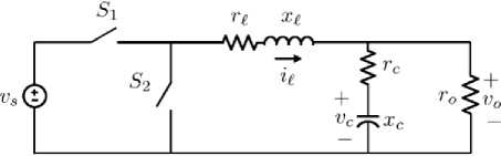
Fig. 1: Step-down DC-DC converter system [1]
Based on the positions of the switches, the DC-DC converter dynamics are changed. Therefore it behaves as a hybrid system. In general, the DC-DC converter has three different modes of operation. It has a linear continuous-time dynamic in each mode. The objective of control for the DC-DC converter is to achieve the desired output voltage by managing duty cycles of switches, but the control problem becomes more complicated when the operating point of the system changes due to variations and uncertainties of input voltage and its load [1].
Here the circuit of the DC-DC converter shown in Fig. 1 is considered. The system is a Fixed-frequency switch-mode DC-DC converter. The primary switch S 1 is always controlled and the secondary switch S operates dually to the main switch. The primary switch is closed at the start of the each period and the control purpose is to decide when the primary switch must be opened within a period to achieve desire output.
In continuous-time the system’s dynamics equations are as follow [1]:
dx ( t )
------= dt vo (t)
where
Fx ( t ) + fv s if kT s < t < ( k + d ( k T
Fx ( t ) if ( k + d ( k )T s < t < ( k + 1)T s
(1.a)
gTx ( t )
(1.b)
T is the sampling time (period
time), k
indicates the time-step, v s is the input voltage, and d is the input signal related to the k -th time-step which is a number between 0 and 1. v o is output voltage of the DC-DC converter.
In the above equations the states should be measured directly. However, v c is not accessible, and therefore the capacitor voltage v c is estimated by output voltage v o [1]. Hence we have:
X (t ) = [ i l (t ) V o (t )]
F =
r l x l

rcr l ------(1 - xc r c —7) r o + r c xl
x l
(1 + xc r c o - ) xc r o + r c x l
xl ro ro + rc
g =[ 0 1 f
du ( k ) = S u ( k ) - d ( k ) (4.b)
where Su is the new state variable and du represents new equation which is the variation of the input signal.
In order to obtain the MLD model (based on (3)) of the DC-DC converter, hybrid system’s description language (HYSDEL) and hybrid toolbox are used [17, 24]. The parameters of converter and the constraints imposed on the system are given in the Table 1.
where r o denotes the ohmic output load, r c is Equivalent Series Resistance (ESR) of the capacitor, and r l is the internal resistance of the inductor. In addition, x c and x l are the capacitance and inductance of the low-pass filtering stage, respectively.
Now in order to achieve discrete-time equations from (1), v -resolution modeling approach is used, and each period is divided into v equal sections [1]. So (1) are rewritten as follow:
Ф ^ ( n ) + T v s
^ ( n + 1) = ^ Ф ^ ( n )
if G n A G n + 1
G n
(2.a)
фАn ) + T ( vd ( k ) - n ) if G n A a n + 1
n
G n = true ^ d(k) > — , n = 0,..., v - 1 v
(2.b)
where § , Ф and T respectively are the discrete-time representation of states, F and f with sampling time T s = f s / v .
According to (2), the system is modeled in the MLD model which has the following structure [16]:
x (k +1) = Ax (k) + B u(k) + B 23(k) + B 3z (k)
y (k) = Cx (k) + D u (k) + D 23(k) + D 3 (k)
E 25(k) + E 3z (k ) < E 1u (k) + E 4x (k) + E 5(3.c)
where x is the system state, y and u are the output and the input signal, respectively. 5 denotes the logical auxiliary variables, and z denotes the continuous auxiliary variables. A , B i ( i = 1,2,3 ), C , D / ( i = 1,2,3 ) and E i ( i = 1,...,5 ) are proper and time-invariant matrixes.
Before obtaining the MLD model of the system based on the discrete-time equations, since one of our goals is to limit the variation of the input signal d near the zero a new state and a new equation is introduced as follow:
Su ( k + 1) = d ( k ) (4.a)
Table 1: The nominal parameters of the converter in p.u. [1]
|
Parameters of the converter |
|||
|
source |
Capacitor |
Inductor |
Load |
|
vs = 1.8 |
xc = 10.294 |
x l = 0.477 |
ro = 1 |
|
rc = 0.001 |
r l = 0.05 |
||
|
il max = 3 |
|||
The number of sections in each period ( v ) is 4, and the MLD model of the system has the following properties:
-
• 3 states (3 continuous: i l ( k ) , vo ( k ) , Su ( k ) -0 binary), 1 inputs (1 continuous: d ( k ) -0 binary), 1 outputs (1 continuous: du ( k ) -0 binary).
-
• 25 continuous auxiliary variables, 7 binary auxiliary variables, 95 mixed-integer linear inequalities.
-
• Sampling time is 1s.
Consequently the matrixes A , B 1 , B 2 , B 3 , C , D 1 , D 2 , D 3 , E 1 , E 2 , E 3 , E 4 and E 5 of the MLD model of the DC-DC system have dimensions of 3 x 3, 3 x 1,
-
3 x 7, 3 x 25, 1 x 3, 1 x 1, 1 x 7, 1 x 25, 95 x 1, 95 x 7, 95 x 25,
95 x 3 and 95 x 1 , respectively.
To evaluate accuracy of the obtained MLD model using v -resolution modeling approach, a coefficient namely ‘coefficient of determination’ is used to show the fitness of the MLD model. The coefficient of determination varies from 0 to 1, where ‘0’ means the model has no relation with the system, and ‘1’ means that the model describes the system perfectly; in other hand the larger value of coefficient of determination indicates a better fitness of the model [25]. The result of computation of the coefficient of determination for MLD model is provided in Table 2.
Table 2: Comparison between the coefficient of determination for two MLD models
In next section, a model predictive control is designed and applied to the system. Its behavior in presence of disturbance and uncertainty is studied.
integer linear program). In inequalities (5.b), b 1 , b 2 , G 1 , H 1 , and H 2 are the proper matrices which define the constraints and guarantee the stability of the system.
Now, according to (5) and subject to the MLD model of the system, a model predictive controller is designed in order to achieve following goals: first output voltage follows the reference voltage, second the variation of the input signal d limits near the zero, and finally the system does not violent the constraints.
The state variables of the step down DC-DC converter are considered as x 1 = q , x 2 = vo and x 3 = S u . The output of system is y = du . So the cost function is defined as follow:
III. Model Predictive Control
Model predictive control is one of the mature and commonplace control approaches which is applied in many practical and academic systems [28-31]. MPC strictly depends on the model of system which is under the control [15,23]. In previous section, a relatively accurate hybrid model of the DC-DC converter was obtained. The hybrid model predictive control (HMPC) is very similar to the conventional MPC but with a slight difference in the cost function the logical and continuous auxiliary variables should be considered [14].
The open loop optimization problem (OOP) in hybrid systems is to minimum the cost function J (.) by meeting the constraints imposed on the controller within a constant prediction’s horizon H p and subject to the system model which here is a MLD model [14]:
J ( У ( k ), x ( k )) =
u ( k ) - 1, 0
H
p
Z ( x 2 ( k + i |k ) - x r 2( k ))
(6.a)
x ( k ) -
(6.b)
min J (u (k ), y (k ), z (k ), x (k )) =
u (k ),^(k ),z (k )
Hp
Z Wx (x (k + i \k)- xr (k ))|| + i = 1 p
H p - 1
Z (| Wu ( u ( k + i\k ) - u r ( k ))||
i = 0 p (5.a)
+1 W z (( k + i ) к ) - z r ( к )| | p +
| Wy ( У ( k + i \k ) - У г ( k ))|| )
in which, the values of the weighting matrix have been determined based on the importance of the variables and the relationships between the variables.
In (6.a) the prediction horizon ( H p ) must be chosen wisely in order to keep the computation time of the OOP in all conditions (nominal, disturbance and uncertainty) less than the sampling time. To select the proper prediction horizon in Table 3 a comparison is provided between maximum computation times of different prediction horizons.
H 1uk - b 1, G 1 xk + H2uk - b 2 (5.b)
Table 3: Comparison between maximum computation time of different prediction horizons
|
Prediction Horizon ( H p ) |
Maximum Computation Time (s) |
|
1 |
Infeasible |
|
2 |
0.004 |
|
3 |
0.123 |
|
4 |
3.801 |
where J (.) is the cost function, and x r , u r , z r and y r indicate reference signals. W x , W u , W z and W y are the proper constant weighting matrices, and the index p indicates the norm which determines the type of the OOP (if p = 2 then the problem is a mixed integer quadratic program and if p = 1, от then it is a mixed
According to the Table 3 all prediction horizon more than one are feasible, but due to the shortage of time for solving the optimization problem, the prediction horizon is set to three.
A traditional MPC scheme is shown in the Fig. 2.
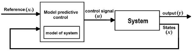
Fig. 2: The block diagram of a conventional MPC method
In order to find the proper input, the OOP should be solved. Due to the cost function (6) is an infinite-norm, the OOP is a mixed integer linear program. In this paper the OOP is solved by using hybrid toolbox which uses the GNU Linear Programming Kit (GLPK) to solve the OOP [24,32]. The cost function (6.a) has been considered in its simplest form to show the efficiency of proposed fuzzy method even without well developed model predictive controllers.
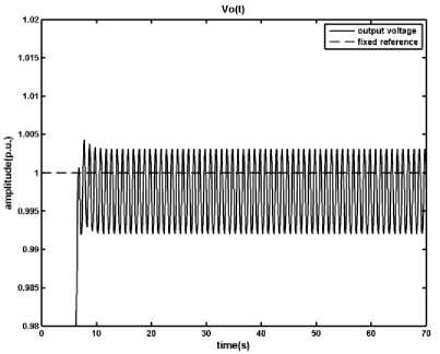
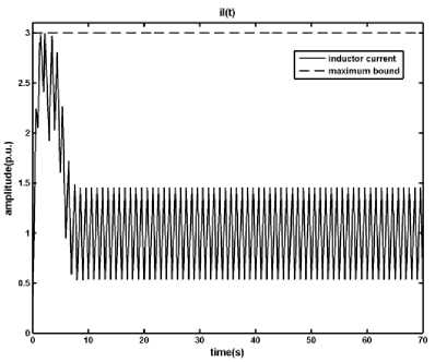
The result of applying the designed MPC controller to the DC-DC converter in nominal startup is shown in the Fig. 3.
According to Fig. 3, the MPC controller which has been designed subject to the MLD model of the DC-DC converter works very good in nominal condition and the persistent error is less than 1 percent. In addition the inductor current is under the maximum allowed amount ( il max ) .
(a)
(b)
(c)
Fig. 3: Results of applying the MPC method on the DC-DC converter, a) output voltage, b) inductor current, c) time in which the primary switch is opened within a period
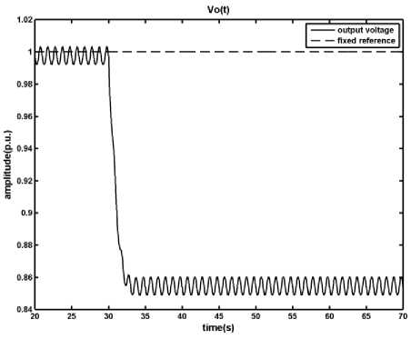
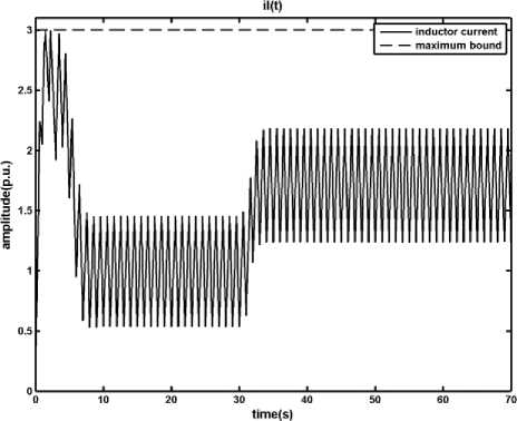
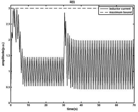
In disturbance condition, two different scenarios are considered one is a sudden increase in input voltage and the other is sudden decrease in output load. For uncertainty condition, due to difficulty of measuring the ESR ( r c ) and the inductance ( x l ), it is assumed that r c and x l have respectively up to 30% and 50% measuring error. In the worse case there are +30% error for r c and -50% error for x l . The results of simulations are shown in Figures 4, 5 and 6.
(a)
(b)
(c)
(c)
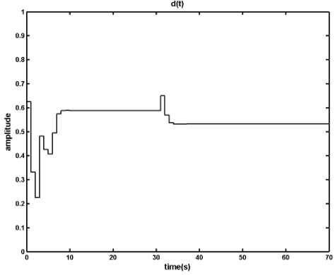
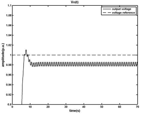
Fig. 4: Results of applying the MPC method on the DC-DC converter in presence of disturbance, load changes from ro = 1 p.u. to ro = 0.5 p.u. at t= 30s, a) output voltage, b) inductor current, c) time in which the primary switch is opened within a period
(a)
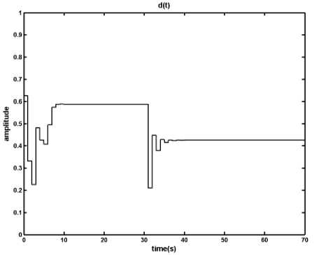
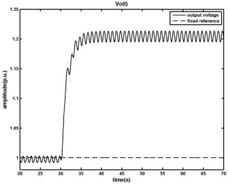
Fig. 5: Results of applying the MPC method on the DC-DC converter in presence of disturbance, input voltage changes from v s = 1.8 p.u. to v s = 3 p.u. at t = 30 s , a) output voltage, b) inductor current, c) time in which the primary switch is opened within a period
(a)
(b)
Fig. 6: Results of applying the MPC method on the DC-DC converter in presence of uncertainty, in the worth case condition r c and x l have respectively +30% and -50% measuring error, a) output voltage, b) inductor current, c) time in which the primary switch is opened within a period
(c)
As it is shown, in the presence of the disturbance and uncertainty designed MPC manages to keep the inductor current under its limit; however the difference between the system and the MLD model, which is used by MPC to produce control signal, causes the output degrades from the reference signal. This digression is not acceptable and should be removed. In the next section a fuzzy model predictive controller is proposed in order to overcome the effects of uncertainty and disturbance in the system.
-
IV. Fuzzy Model Predictive Control
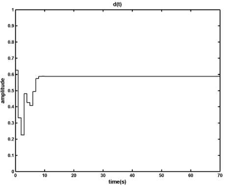
The MPC method, as shown in previous section, is very sensitive to the model of the system. Uncertainty and disturbance cause difference between the model and system which appears as tracking error. In this section, we propose a Fuzzy predictive control scheme which solves this problem without increase in the complexity of the MLD model which costs a lot computational effort. In the proposed method a fuzzy supervisor is used in order to regulating the reference signal of the MPC based on the measured state variables. The proposed scheme is shown in Fig. 7.
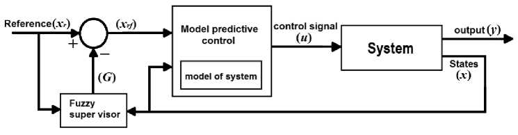
Fig. 7: The block diagram of MPC method with fuzzy supervisor
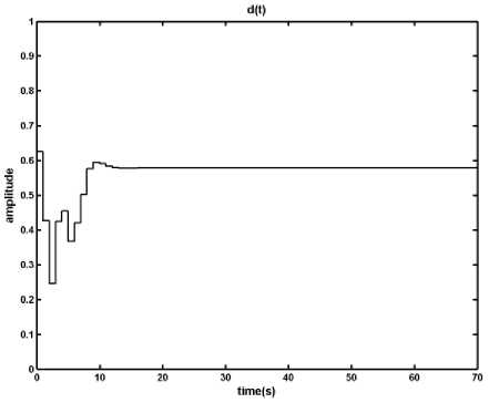
In the proposed scheme, the MPC part is not modified, but the reference signals of MPC block is defined as follow:
J ( y ( k ), x ( k )) =
^ ( x 2 ( к + i k ) - x rf 2 ( к))
i =1
да
x rf ( k + 1) = x r ( k ) - G ( k ) (7.a)
G ( k ) = F ( k ) + F ( k - 1) (7.b)
+ Z (i0j y ( k + i i k ) да ) i = 1
where x rf and x r ( k ) are the actual reference signals and fuzzy-based reference signals, respectively. F represents a fuzzy function ( F ( k ) = 0, k < 0 ). Consequently the cost function (6.a) should be rewritten as follow:
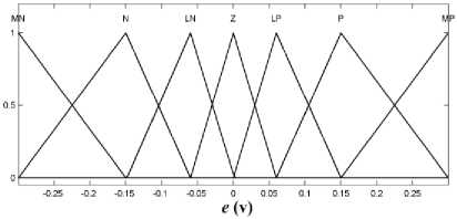
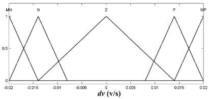
Now, the inputs of the fuzzy system for DC-DC converter should be defined. Based on our goals which are decreasing output error and avoiding from excessive output oscillation around desire value, two variables e ( k ) and dv ( k ) are proposed as inputs of the fuzzy system, where
e ( k ) = x r 2 ( k ) - x 2 ( k ) (9.a)
dv ( k ) = x 2 ( k ) — x 2 ( k — 1) (9.b)
where e ( k ) and dv ( k ) represent tracking error (in volt) and output’s change (in volt per second), respectively.
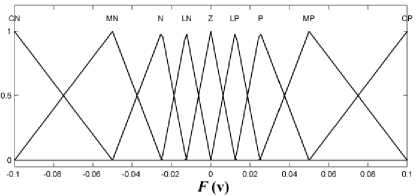
In Fig. 8, the fuzzy system including a Mamdani-type fuzzy inference system is depicted. This system uses minimum inference engine. Triangular membership functions are used to create fuzzy sets from input signals due to their simplicity and ease of use. Center average defuzzifier is also used to generate output signal. Membership functions of fuzzifier and defuzzifier are shown in Fig. 9. In Table 4 the definition of CN, MN, N, LN, Z, LP, P, MP, and CP have been provided.
Table 4: Definition of CN, MN, N, LN, Z, LP, P, MP, and CP
|
Symbol |
Meaning |
|
CN |
the variable is completely less than the desired value |
|
MN |
the variable is high less than the desired value |
|
N |
the variable is less than the desired value |
|
LN |
the variable is a little less than the desired value |
|
Z |
the variable has desired value |
|
(For CP, MP, P and LP “less” shall be replaced with “more”) |
|
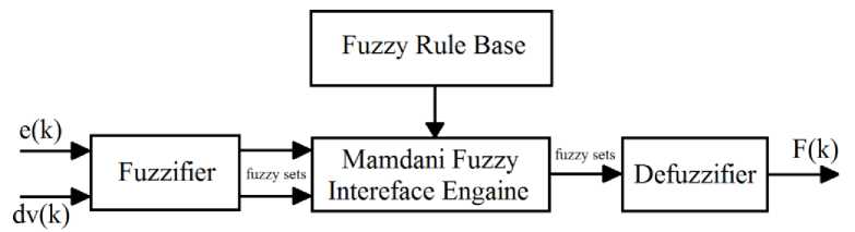
Fig. 8: Inner structure of the fuzzy system
(a)
Fig. 9: Membership functions, a) Membership function of e , b) Membership function of dv , c) The output of fuzzy system F
In Fig. 9 triangular membership functions for inputs and output have been defined specifically to reduce the output error and avoiding from excessive output oscillation around desired value. The triangular membership functions in Fig. 9 have a mathematic equation as follow:
(b)
(c)
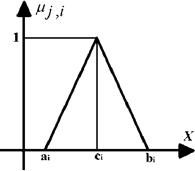
Fig. 10: A single membership function
PjA x) = ‘
( c, - a )
( x - a ,)
a, < x < c
( C i - b д
(x - bd
C < x < b,for otherw se
j = e jj = dv j = F
and and and
i = MN ,
...
, MP
i = MN , N , Z , P , MP
i = CN ,
...
, CP
where ^ t is a triangular membership function and a , b , c are proper constant parameters which define the boundaries of triangular membership function.
Consequently, the weight of the i -th ( i = CN ,..., CP ) membership function for output (Fig. 9.c) equals to the minimum weight of the all membership functions ^ j , i ( j = e , dv , i = MN ,..., MP ) for inputs (Figures 9.a and 9.b) which are related to the i -th output membership function according to the Table 5. To convert the fuzzy sets to the output signal, the center average defuzzifier is used with following equation.
in which, y is the center ( c in Fig. 10) of i-th ( i = CN ,..., CP ) triangular membership function (Fig. 9.c), and ^ is the weight of the i -th ( i = CN ,..., CP ) membership function for the defuzzifier.
The fuzzy rules are presented in the Table 5. The fuzzy rules are chosen based on analyzing the simulations of system behavior with model predictive controller in presence of disturbance and uncertainty. The general form of rules is as the following statement:
If e is … and dv is … then F is ….
where ‘...’ should be filled according to the Table 5.
F = 2^MFiyl , i = CN,...,CP 2, ^F.
Table 5: Law data base
|
e dv |
MN |
N |
LN |
Z |
LP |
P |
MP |
|
MP |
MP |
MP |
MP |
Z |
MN |
MN |
MN |
|
P |
CP |
CP |
LP |
Z |
LN |
CN |
CN |
|
Z |
Z |
MP |
P |
Z |
N |
MN |
Z |
|
N |
CP |
CP |
LP |
Z |
LN |
CN |
CN |
|
MN |
MP |
MP |
MP |
Z |
MN |
MN |
MN |
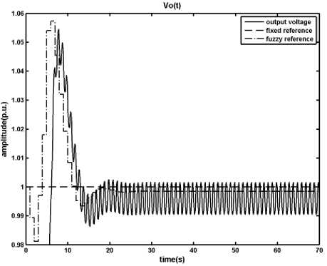
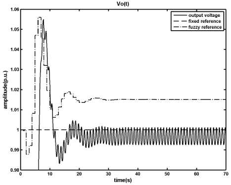
Know based on the proposed method a fuzzy predictive controller is designed and applied to the DCDC converter under the same condition as before, the result of nominal condition is shown in Fig. 11.
By applying the fuzzy predictive control to the DCDC converter, as shown in Fig. 11, it is clear that the fuzzy predictive controller converges the output voltage toward the desirable value, however it increases the overshoot (undershoot) of the output in nominal condition. Moreover the proposed controller satisfies all constraints of the system and keeps the inductor current within its boundary.
The disturbance and uncertainty conditions are same as the previous section; the results of applying designed fuzzy predictive controller are shown in Figures 12, 13 and 14.
(a)
(b)
(b)
(c)
(c)
Fig. 11: Results of applying the Fuzzy Predictive Control on the DCDC converter, a) output voltage, b) inductor current, c) time in which the primary switch is opened within a period
(a)
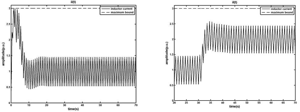
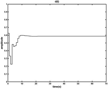
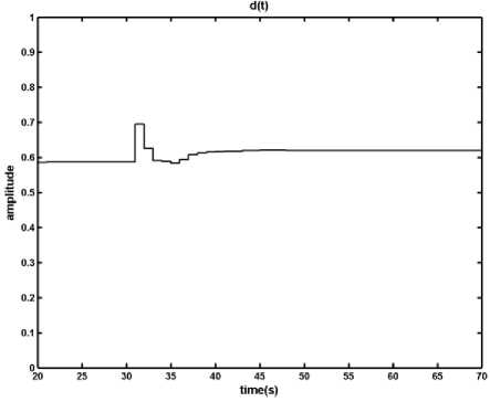
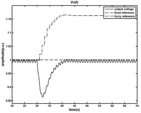
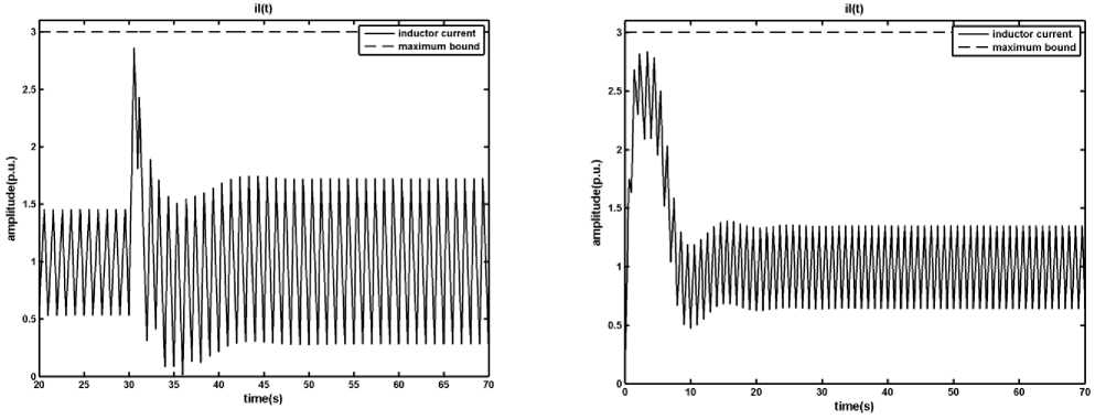
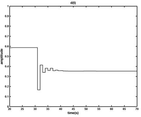
Fig. 12: Results of applying the Fuzzy Predictive Control on the DC
DC converter in presence of disturbance, load changes from r o = 1 p.u. to r o = 0.5 p.u. at t = 30 s , a) output voltage, b) inductor current, c) time in which the primary switch is opened within a period
(a)
(b)
(b)
(c)

(c)
Fig. 14: Results of applying the Fuzzy Predictive Control on the DCDC converter in presence of uncertainty, in the worth case condition r c and x l have respectively +30% and -50% measuring error, a) output voltage, b) inductor current, c) time in which the primary switch is opened within a period
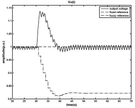
Fig. 13: Results of applying the Fuzzy Predictive Control on the DCDC converter in presence of disturbance, input voltage changes from v s = 1.8 p.u. to v s = 3 p.u. at t = 30 s , a) output voltage, b) inductor current, c) time in which the primary switch is opened within a period
(a)
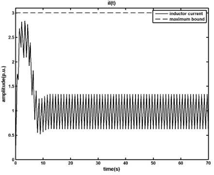
According to Figures 12, 13 and 14, In contrast with the MPC case in which the disturbance and uncertainty caused a persistent error in output voltage, the proposed fuzzy predictive control by regulating the reference signal of the DC-DC converter based on its state variables removes the persistent error in the output voltage in presence of disturbance and uncertainty. In addition it keeps the inductor current under the maximum allowed value.
As presented in this paper, the proposed fuzzy predictive control method reduces the effects of uncertainty and disturbance significantly. In addition, in contrast with the proposed method in [1] which is based on modifying the MLD model, the proposed method doesn’t increase the computational effort while increasing the robustness of the controller. The proposed method provides opportunity to easily develop a more robust controller for more complicated scenarios in order to make a more comprehensive fuzzy predictive controller.
-
V. Conclusion
In this paper, a fuzzy supervisor was proposed in order to design a simple but powerful robust controller. The proposed method modifies reference signal of the model predictive control. It was shown that proposed approach can easily overcome the effects of disturbance and uncertainty. The proposed fuzzy predictive control has many advantages in the DC-DC converter: It has less complexity to overcome the disturbances and the uncertainties, and it gives enough freedom to manage the controller. The desired output can be achieved by only measuring states which are necessary for traditional MPC. In addition, the control signal and output in each step are optimal because of the existence of the cost function in MPC method. Through simulations the simplicity and efficiency of the proposed method in normal operation, and strong robustness in the presence of disturbances and uncertainties in comparison with the conventional MPC method were shown.
References Fuzzy Predictive Control of Step-Down DC-DC Converter Based on Hybrid System Approach
- J. Kennedy, R. C. Eberhart. Particle swarm optimization. Proceedings of the IEEE International Conference on Neural Networks IV, IEEE Press, Piscataway, NJ (1995), pp.1942–1948.
- Geyer T, Papafotiou G, Morari M. Hybrid model predictive control of the step-down DC–DC Converter. IEEE T Cont Syst Tech, 2008, 16: 1112~1124.
- Middlebrook RD, Cuk S. A general unified approach to modeling switching power cnverter stages. In: IEEE Power Electronics Specialists Conference, June, 1976, Cleveland, Ohio, USA: 18~34.
- Kassakian JG, Schlecht MF, Verghese GC. Principles of power electronics. 1st ed. USA, Addison-Wesley, 1991.
- Hamill DC, Deane JHB, Jefferies D. Modeling of chaotic dc-dc converters by Iterated nonlinear mappings. IEEE T Power Electron, 1992, 7: 25~36.
- Mohan N, Undeland TM, Robbins WP. Power electronics: converters, applications and design. 1st ed. USA, Wiley, 1989.
- Hsien C, Sheng L, Lee R, Chen K. Analysis and implementation of a dc-dc step-down converter for low output-voltage and high output-current applications. In: IEEE International Symposium on Circuits and Systems, June, 2010, Paris, France: 3697~3700.
- Mazouz N, Midoun A. Control of a dc-dc converter by fuzzy controller for a solar pumping system. Int J Electr Power Energy Syst, 2011, 33: 1623~1630.
- Ismail EH. Large step-down dc–dc converters with reduced current stress. Energy Conver and Manag J, 2009, 50: 232~239.
- Mariethoz S, Almer S, Baja M, Beccuti AG, Patino D, Wernrud A, Buisson J, Cormerais H, Geyer T, Fujioka H, et al. Comparison of hybrid control techniques for buck and boost dc-dc converters. IEEE T contr syst, 2010, 18:1126~1145.
- Beccui AG. Explicit model predictive control of dc-dc switched mode power supplies with extended Kalman filtering. IEEE T Ind Electron, 2009, 56: 1864~1874.
- Diaz NL, Soriano JJ. Study of two control strategies based in fuzzy logic and artificial neural network compared with an optimal control strategy applied to a buck converter. In: Annual Meeting of the North American Fuzzy Information Processing Society, June, 2007, San Diego, CA, USA: 313~318.
- Erickson RW, Cuk S, Middlebrook RD. Large signal modeling and analysis of switching regulators. In: IEEE Power Electronics Specialists Conference, Aug, 1994, Barcelona, Spain: 240~250.
- Kostakis GT, Manias SN, Margaris NI. A generalized method for calculating the RMS values of switching power converters. IEEE T Power Electron, 2000, 15: 616~625.
- Camacho EF, Ramirez DR, Limon D, Munoz D, Alamo T. Model predictive control techniques for hybrid systems. Annu. Rev. in Control, 2010, 34: 21~31.
- Antsaklis PG, Koutsoukos XD. Model predictive control past present and future. Comput Chem Eng, 1999, 23: 667~682.
- Bemporad A, Morari M. Control of systems integrating logic, dynamics, and constraints. Automatica, 1999, 35: 407~427.
- Torrisi FD, Bemporad A. HYSDEL-a tool for generating computational hybrid models for analysis and synthesis problems. IEEE Trans. on Control Syst. Technol. 2004, 12: 235~249.
- Takagi T, Sugeno M. Fuzzy identification of systems and its application to modeling and control. IEEE Trans. on Man Cyber. 1985, 15: 116~132.
- Ershadi MH, Poudeh MB, Eshtehardiha S. Fuzzy Logic Controller Based Genetic Algorithm on the Step-down Converter. In: International Conference on Smart Manufacturing Application, April, 2008, Goyang-Si, South Korea: 324~328.
- Mojica E, Quijano N. A replicator dynamics weighted control technique for a dc-dc converter. In: IEEE Congress on Evolutionary Computation, June, 2011, Ritz Carlton, New Orleans, USA: 1872~1878.
- Ramirez H. Nonlinear P-I controller design for switch mode dc-dc Power converters. IEEE Trans. on Circ. Syst. I, 1991, 38: 410~417.
- Lazar M, Keyser R. Nonlinear predictive control of a dc-to-dc converter. In: International Symposium on Power Electronics, Electrical Drives, Automation and Motion, June, 2004, Capri, Italy: 1~5.
- Clarke DW, Mohtadi C, Tuffs PS. Generalized predictive control : the basic algorithm. Automatica, 1987, 23: 149~160.
- Bemporad A. Hybrid Toolbox v.1.2.6. http://control.ee.ethz.ch/~hybrid/
- Nagelkerke NJD. A note on a general definition of the coefficient of determination. Biometrika, 1991, 78: 691~692.
- Sarailoo M, Rahmani Z and Rezaie B. Modeling of Three-Tank System with Nonlinear Valves Based on Hybrid System Approach. J. of Control Eng. and Technol. 2013, 3: 20~23.
- Sarailoo M.; Rahmani Z.; Rezaie B. MLD Model of Boiler-Turbine System Based on PWA Linearization Approach, International J. of Control Science and Engineering, 2012, 2: 88~92.
- Lawrnczuk M. On improving accuracy of computationally efficient nonlinear predictive control based on neural models. Appl. Soft Comput. 2011, 66: 5253~5267.
- Gerkšič S and Pregelj B. Tuning of a tracking multi-parametric predictive controller using local linear analysis. IET Control Theory Appl. 2012, 6: 669~679.
- Huang H, Li D and Xi Y. Design and input-to-state practically stable analysis of the mixed H2/H feedback robust model predictive control. IET Control Theory Appl. 2012, 6: 498~505.
- Wang Y, Zhang Y, Sun F, et al. Using subset sequence to approach the maximal terminal region for model predictive control. IET Control Theory Appl. 2012, 6: 596~601.
- Makhorin A. Glpk (gnu linear programming kit), 2007, version 4.42.
