Fuzzy Sliding Mode Control Scheme for Vehicle Active Suspension System Optimized by ABC Algorithm

Author: Atheel K. Abdulzahra, Turki Y. Abdalla
Journal: International Journal of Intelligent Systems and Applications @ijisa
Article in issue: 12 vol.11, 2019.
Free access
This paper suggests a proposed control scheme of fuzzy sliding mode and PID controller tuned with Artificial bee colony (ABC) algorithm to control vehicle suspension system. Suspension systems are utilized to provide vehicles safety and improve comfortable driving. The effects of the road roughness transmitted by the tires to the vehicle body can be reduced by using suspension systems. Fuzzy system is used for estimating the unknown parameters and uncertainty in the suspension system components (spring, damper and actuator). This study combines sliding mode with fuzzy strategy to design a robust control method. The ABC technique is used to optimize the controller parameters. The suggested control scheme endeavors to limit the vibration of the vehicle body by creating a suitable force for the suspension systems when passing on disturbance. Passive and active suspension systems are compared to test efficiency and ability of the proposed control scheme to enhance the safety and comfortable driving for different road profiles.
Fuzzy estimator, Sliding mode control, ABC algorithm, PID controller, Active suspension system
Short address: https://sciup.org/15017112
IDR: 15017112 | DOI: 10.5815/ijisa.2019.12.01
Text of the scientific article Fuzzy Sliding Mode Control Scheme for Vehicle Active Suspension System Optimized by ABC Algorithm
Published Online December 2019 in MECS
The fundamental aim of suspension system is to limit movements of the vehicle body because of road roughness. The perturbations actuated by the road roughness and load when a vehicle moves along a road can be minimized using suspension system. Also, suspension system of vehicle detaches the vehicle body from its wheels and gives the comfortable driving, better dealing with road, and stability of the vehicles [1,2,3]. Springs, shock absorber and linkages represent the components of the suspension system which is used to associate the wheels of vehicle with its body. The passive components with actuators that give an extra forces, implement an active suspension system. The suspension deflection and the acceleration of the sprung mass can be decreased with active suspension system [4,5]. Many control methods have been considered to control the active suspension system of the vehicle.
This work, presented a control approach that use fuzzy logic, sliding mode concept and PID controller optimized by ABC algorithm for the control of active suspension system. The position of sprung mass is controlled using sliding mode controller, while the fuzzy system estimates the unknown parameters of the system and the PID controller is used to control the force produced by the actuator. The ABC algorithm is used to optimize the parameters of the controller.
In the following sections, the related works is presented in section 2. The mathematical model of a quarter vehicle is described in section 3. The design procedure of sliding mode controller is discussed in section 4. The proposed control scheme is presented in section 5. Results are shown in section 6.
-
II. Related Works
Many control methods have been developed to control the suspension system of the vehicle. The PID controller tuned by particle Swarm optimization method was used for quarter active suspension system and compared with passive suspension system for various road profiles. PID controller tuned with Artificial Bee Colony (ABC) optimization technique was used for nonlinear full active suspension system with traveler seat [6,7,8]. Fuzzy Logic Controller (FLC) has shown up as another technique to control a vehicle active suspension system [9,10]. Many studies used Sliding Mode Control (SMC) which represents a robust controller in suspension systems [11,12]. The sliding mode control is a simple control technique and it ensures system stability [13]. Fuzzy sliding mode controller (FSMC) has been used to diminish chattering that exists in the control output because of the discontinuous control segment in the control law [14,15,16].
In this paper, a new control scheme that use fuzzy logic, sliding mode control and PID controller optimized by ABC algorithm was proposed. The position of sprung mass can be controlled using sliding mode controller, fuzzy system is used to estimate the unknown parameters of the system based on Minimum Parameter Learning (MPL), and the PID controller is used for controlling the force produced by the actuator. The ABC algorithm is used to select the best values of PID gains that give good results for different road profiles and disturbances. The ABC algorithm can be used to achieve multi objective design criterion.
-
III. Mathematical Model of Quarter Vehicle
In this study, a quarter vehicle active suspension system is used to test the performance of the proposed control scheme. Many researchers are used the quarter vehicle active suspension system due to its simplicity and also it gives a good representation for the real active suspension system [17]. The passive components with an actuator forms the active suspension systems as appeared in Fig. 1 and Fig .2.
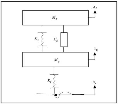
Fig.1. Quarter vehicle model (Passive)
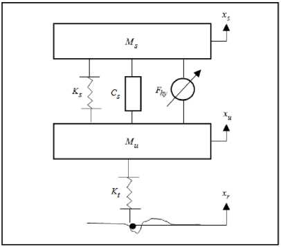
Fig.2. Quarter vehicle model (Active)
According to Newton's laws, the mathematical model of the quarter active suspension system can be expressed as:
Sprung mass:
M s x s + K s ( x s - x u ) + C s ( x s - x s ) - F hy = 0 (1)
Unsprung mass:
M u x s + K t ( x u - x r ) - K s ( x s - x u ) - C s ( x s - x u ) + F hy = 0
Where, M and M represent sprung mass and unsprung mass of the vehicle body respectively. The tire is designed as a linear spring with stiffness K . The linear damping and stiffness of the suspension system are modeled as C and K respectively. The displacement of the body, road profile and the wheel represent the variables ( x , x and x ) respectively. The hydraulic actuator force is F . When the hydraulic actuator force F hy = 0 , (1) and (2) yield the passive suspension system model. The spool valve system is modeled as [18]:
x v = -(- x v + K^ ) (3)
T
The time constant for servo-valve is ( t ), which represents a mechanical delay time, ( K ) is the conversion gain and ( u ) is the control input. The hydraulic cylinder is described by the dynamic equation:
. ..
F hy = -c A p ( x s - x u ) - P Fhy + Y s A p X v

F hy sgn( x v ) A p
The parameters ( c , в and ys ) are parameters of a hydraulic actuator which may be time varying. The piston area is ( A ) and the pressure of hydraulic supply is ( P ). The state space form of the quarter vehicle active suspension system with hydraulic dynamic can be written as:
Where;
.
x = Ax + BF hy + B w Xr
T
X = [ X 1 , X 2 , X 3, X 4 ]
The body displacement is X ] = x ^, the velocity of the
.
body is x 2 = X s , the unsprung mass displacement is
.
x 3 = xu and the velocity of the unsprung mass is x 4 = xu . The state space equations of the active suspension system, with hydraulic dynamics are rewritten as:
disturbances and limit the effect of improper disturbances on the system, the SMCs are widely utilized. SMCs are used for non-linear system [20].
Consider the suspension system state model as in (5):
.
X 1 = X 2
.
X 2 =
— K^x
Ms 1
—
CKC 1
—X , + — x , + — x4 + — F h y
M s hy
M s
M s
M s
K
X 4 = --- X,
4 M u 1
+ C^
Mu 2
—
1 F M u hy
X 3 = X 4
( K s + K t )
M u
x
Cs t mJ4 " X
K
t
M u
r
Where;
x g R n : State vector of the system
F g R m : Input of the system
A g R n * n : System matrix
B g Rn*m : Matrix of control input and x : Road profile.
When the switching surface s ( x , t ) is varied with time, it can be expressed as:
s ( x , t ) = Cx
The matrices ( A , B and B ) are the state, control
s = C 1 X 1 + c 2 X 2 + c 3 X 3 + ... + x n
input, and road input matrices
A =
are given as:
|
0 |
1 |
0 |
0 |
0 |
|
|
K s |
C s |
K s |
C s |
1 |
|
|
M s |
M s |
M s |
M s |
, B = |
“ ■ |
|
0 |
0 |
0 |
1 |
0 |
|
|
K s |
C s |
( K s + K t ) |
C s |
1 |
|
|
M u |
M u |
M u |
M u |
M u |
|
,
B w
The Lyapunov function is designed as, V = —s , V is a positive definite, the system trajectory will be reached .
the sliding surface as [21], when V < 0 is satisfied according to Lyapunov theorm:
.
s ( x , t ) = 0
The control law that satisfies the conditions of (SMC) is designed as:
F hy = F hyeq — k sgn( s )
M u
The dynamic equation of sprung mass is given by:
.. 1
x 1 = f ( x , t ) + — F hy Mu
The function f (x, t) is assumed unknown function and to be estimated.
f ( x , t ) = — KT X 1
M s 1
—
CKC ----x7 +-- x 3 +-- x4
M s 2 M s 3 M s 4
-
IV. The Design of Sliding Mode Controller
Sliding mode control is a powerful and simple structure that can be intended for a system with uncertainties and it is a variable structure firstly used by Utkin in [19]. Since SMCs are able to overcome
Where, F is the equivalent control input and k is a constant.
-
V. Proposed Control Scheme Design
The proposed control scheme is shown in Fig. 3. It is based on the work in [17]. The position control of the vehicle body will be performed with the value of desired input signal ( x ) which equals zero. The PID controller is optimized using ABC algorithm and it is used in the inner loop to control the actuator and create the required force. The fuzzy system is used here for estimating the unknown function f ( x , t ) . Fuzzy system is widely used as controller or estimator in many applications [22-27] and it is used here together with the Sliding Mode controller as an estimator for the unknown parameters.
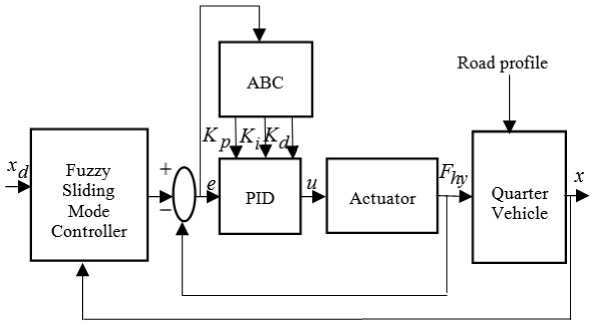
Fig.3. Block Diagram of Proposed Control Scheme
-
A. Fuzzy Sliding Mode Control (Fsmc) Of A System Using Minimum Parameters Learning
The Minimum Parameter Learning (MPL) technique [28] can minimize the number of an adaptive elements to a single element that can be utilized in fuzzy system in order to decrease the extra calculations and enhance the performance of the real time system.
Define the tracking error as:
e = x1 - xd(18)
The sliding mode function is described as:
5 = e + ce(19)
The convergent rate of x is c , and c > 0
-
. .. . .. .. . 1
-
5 = e + ce = x 1 - xd + ce = f (x, t) +--Fd + cx 1
M u
The desired force is ( F ), the control law is implemented as:
.
F d = M u ( - f ( x , 1 ) - cx - П sgn( 5 )) (2 1)
We have, 5 5 = -n 5 < 0, where 5 = - n sgn( 5 ) [29]. When f ( x , t ) is unknown, we will replace f ( x , t ) with the estimated values f ( x , t ) to realize the control law. The uncertainty estimation using the fuzzy system includes the following steps:
ll
-
1. For x 1 , x 2 , x 3 and x 4 , define the fuzzy sets A i , A i , ll
-
2. Design the fuzzy
-
3. The fuzzy system output is:
A3 , and Ад respectively, lz = 1,2,3,4,5.
rules §(x) = П Pi = pi x P2 x Рз x P4 in order to design i=1 , the fuzzy system f (x | 9f) as:
Rule (1) : If x is A 1 and x is A 1 and x is A 1 and x is
A 1 then f ˆ is B 1 , to…
Rule(625) : If x is A5 and x is A5 and x is A5 and x is A5 then fˆ is B625 .
Where, p 1 = p 2 = p 3 = p 4 = 5 .
5 5 5 5 llll 4 l
Z Z Z Z . ^ Zl p (x i ))
-
„ l = 1 l = 1 l = 1 l = 1 i = 1 i
f ( X 9f ) = 1 25 35 45 5 4 l ---------- (22)
Z Z Z Z ( П p ( x i ))
l = 1 l = 1 l = 1 l = 1 i = 1 i
l
Where; pj (xt) is the membership function of xt , i llll which is a Gaussian function and y 1 2 3 4 be a parameter in the group 9f eRule(625) , x = [x1,x2,x3,x4] , and
^ ( x ) = П p, = p i x p 2 x p 3 x p4 = 625 ,is a column vector. i = 1
Equation (22) can be written as:
f ( x| 9 f ) = 9 T §< x )
-
4 l
П P'a ( x i )
^ iiii ( x ) =wi=zr-------
-
1 2 3 4 p 1 p 2 p 3 p 4 4 l
Z Z Z Z ( П P A ( x i ))
l = 1 1 = 1 1 = 1 1 = 1 i = 1
Assume the ideal parameter is:
9, = arg min
1 9 efi ff
sup f ( x | 9 f ) - f ( x )
x e Rn
Where, Ω is a set of θ . The term “ f “ can be implemented as:
f=θ∗fTξ(x)+ε(26)
Where ε is an estimation error of the fuzzy system, approximation “ f “ is:
fˆ(x|θf)=θˆfTξ(x)(27)
By using Minimum Parameter Learning [29], express a positive constant as φ = θ ∗ II and let φ ˆ an estimate of φ . The controller can be designed as:
1T uc = - sφξTξ+ xd -ce-ηsgn(s) - µs(28)
Where; η ≥ ε and µ > 0 . The Lyapunov function will be characterized as:
V=1s2+1φ2(29)
22 γ
Where; φ = φ ˆ - φ and γ is positive.
.. 1 .
V =ss+φφˆ(30)
γ
The adaptive law is designed as:
.
φ垐=γ s2ξTξ-κγφ(31)
2µ
Where, κ = and, κ > 0 . Solving V ≤ - 2 µ V + Q to
γ imply that:
lim V = φ + 1 (32)
t →∞ 2 γ 4 γ
Where, Q = κφ 2 + 1 .
From (32) we can see that accuracy of convergence based on ( γ ) and ( µ ) parameters. The sliding surface converges to zero finally.
-
B. The Optimization Of Parameters Of Pid Controller Using Abc Algorithm
The standard form of PID controller is based on loop feedback mechanism and the estimation of an error signal, an error signal represents the difference between actual signal and a reference signal [30].
The design of the PID controller will provide a stabilization for the system and a suitable system performance [31]. The equation of the PID controller is implemented as:
t u=K e+K ∫edt+K e (33)
Where; u is the output of PID controller, “ K “, “ K ”and “ K “ are the proportional, the integral and the differential gains respectively. The error ( e ) is given by:
e = F d - F hy (34)
The desired force ( F ) is generated by FSMC and the actual actuated force is ( F ). Artificial Bee Colony (ABC) algorithm was proposed by Dervis Karaboga in 2005 [32]. It is used to describe the rummaging conduct of bee colonies. There are three groups of bee colonies, the employed bees, onlooker bees and scout bees. They are all tasked to search about the sources of food. Initially the places of food are created randomly [33]. The number of employed bees and onlooker bees are equal to the number of sustenance source. The employed bees try to search about the sustenance source and store the data about its quality. When the sustenance source becomes deserted, the employed bees will be scout and then search about another sustenance source to become employed again. The sustenance source represents an optimal solution to the optimization issue while the nectar quantity sources matches to the solution fitness [34]. The employed bees choose food source (solutions) randomly, and discover the food source and its neighborhood in each iteration, then compute the nectar quantity. If the fitness of the selected food source is better than the old one, they choose that food source else return to old one. The employed bees and onlooker bees are sharing with the same data, and the last evaluate the information and select the best food source. The (ABC) method used in this work can efficiently find a suitable gain parameters for the controller. It is aimed to minimize the acceleration and displacement of the vehicle body as well as the amount of suspension deflection. The ABC algorithm can be used to achieve multi objective design criterion and the fitness function may be selected to contain one or more terms of the cost functions like:
N N ..
cost1 = ∑ xs2i , cost2 = ∑xsi , cost3 =∑(xsi -xui)2(35)
i =1 i =1
The design of PID controller parameters is performed using ABC algorithm. The following steps involves a brief summary for ABC algorithm [33-35].
-
1) Initialize ABC parameters such as (maximum number of cycle, colony dimension, parameter limits).
-
2) Produce an initial population of Food Sources K
( FS ) individuals randomly. Each solution sou , K sou = [I,2,..., FS ] represents a d — dimensional vector corresponded to PID parameters where, D = [ K p K i K d ]
-
3) Evaluate the fitness function of each solution as:
fitness =----— (36)
1 + cos t
-
4) Set the number of cycle counter to 1. The solutions will be modified and changed with a new solution ( Kie w ) by employed bees. The better solution which is placed by each employed bee is described as in the following equation:
Table 1. Physical parameters of the hydraulic actuator
Sample
Value
о
4.515 x10 13 N / m
в
1 s
Y s
1.545 x10 9 N / mkg
P sup
10.3425 x10 6 Pa
A p
3.35 X10 - 4 m 2
T
1/30 s
Kc
0.001 m / V
K new ( s , j ) = K ( s , j ) + ^ ( s , j X K ( s , j ) - K ( n j )) (37)
Where, n = 1,2,..., FS , ( n ^ s ) and j = 1, 2, 3 are randomly selected and d ( s , j ) e (0,1) .
-
5) Compute the selection probability values ( P ) for each employed bee. According to these probability values, each onlooker bee produce new solution ( Kie w ) as in (37). Then calculate the fitness function of each new solution as give in (36), a greedy selection is applied between the new and old solution in order to save the best solution and ignore the other one.
-
6) If the food source is not improved over an iterations number, that source deserted and changed with another one which is generated randomly by scout bees. This process is made according to the parameter limit.
-
7) Save the track of the best solution and increase the cycle counter. Steps between (4 and 7) are repeated until reach the maximum number of cycle. If the maximum numbers of iterations have satisfied, stop and return the best solution found.
VI. S imulation R esults
Consider the quarter vehicle models as shown in Fig. 1 and Fig .2. The parameters of the hydraulic actuator and vehicle suspension system are given in Table 1 and Table 2 respectively. The robustness and effectiveness of the active suspension system compared with passive suspension system subject against various types of road profiles are discussed in this study. Three types of road profiles will be used.
Table 2. Physical parameters of the quarter vehicle suspension system
Sample
Value
Ms
290 kg
Mu
59 kg
Ks
16812 N / m
Kt
190000 N / m
Cs
1000 N / m
1. Case (1): In this case a single sine bump is applied as road profile taken from [17] and it is shown in Fig. 4.
0.5 h (1 + sin(2 n vt )
X r 1 = <
L 0
0.2 < t < 0.7
otherwise
Where; h = 0.05 m, is the height of the bump, L = 2.5 m is the length of the bump, and the velocity of the vehicle is v = 5 m/s.
2. Case (2): The second road profile is assumed to have two bumps as shown in Fig. 5 [36].
a (1 - cos(8 n t ))
X r 2 4
0.5 < t < 0.7 and 3 < t < 3.25
otherwise
Where; a is the bump amplitude and a = 0.05.
3. Case (3): The third road profile is assumed to be a random road profile which can be approximated by Power Spectrum Density PSD in the form [37]:
Ф ( n ) =Ф ( n o )( n ) - w
n o
-
Where, n is the reference spatial frequency and the spatial frequency is n . Choose the road roughness Ф ( no ) = 64 x 10 - 6 m , no = 0.127 and w = 2 . The PSD represent the third road profile that is generated by integrating a white noise signal as shown in Fig. 6.
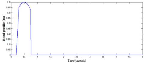
Fig.4. Road profile 1
In the simulation the Fuzzy Sliding Mode Controller for the active suspension system is compared with passive suspension system.
The parameters that are chosen for the controller are c = 10 , у = 0.0001 , and ц = 10 . The parameters K , K and K of PID controller are tuned by ABC algorithm, the ranges of these parameters are chosen as:
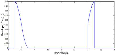
Fig.5. Road profile 2
K p , K , and K d e [0 500].
The parameters selected for ABC algorithm are given in Table 3. The fitness function is selected as in (36) and (37). Five Gaussian membership function with centers ( ц = 1 , ц 2 = 0.5 , ц 3 = 0 , ц 4 = - 0.5 , and ц 5 = - 1) are used for the inputs of the fuzzy estimator as shown in Fig.7. The optimal PID controller parameters after optimization using ABC algorithm are determined as:
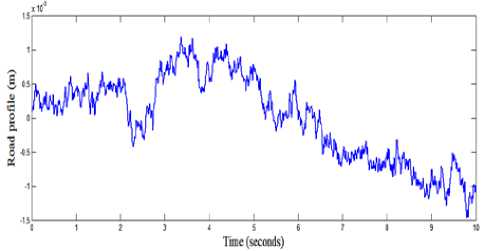
Fig.6. Road profile 3
K = 70.0851, K = 210.3024 and K, = 457.7836. pid
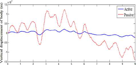
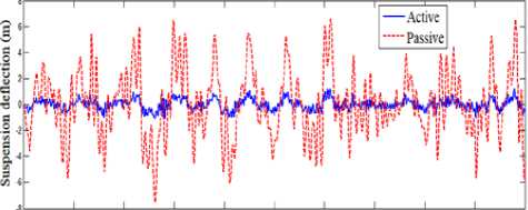
Simulation of quarter vehicle active suspension using MATLAB/SIMULINK software is performed. Performances of the suspension system in term of ride quality and vehicle handling is observed, with road disturbance is assumed as external input for the system. Simulation results of the quarter vehicle active suspension system for the three road profiles with the proposed controller is compared with that of passive suspension system. The true and estimated forces of control input are given in Fig. 8, Fig. 12, and Fig. 16, where, these figures showed that the estimated force of control input are converged to the true force of control input. The vertical displacement of the vehicle body is shown in Fig. 9, Fig. 13, and Fig. 17, where these figures showed that the extreme amplitude of the sprung mass displacement responses are improved and converged to nearly zero by proposed control method. The suspension deflection is shown in Fig. 10, Fig. 14, and Fig. 18, which are reduced and well improved. The body acceleration is shown in Fig. 11, Fig. 15 and Fig. 19, which are also, gave a good results. So, the fuzzy sliding mode controller strategy has a superior performance and gives a best dynamic properties.
Table 3. The parameters of ABC algorithm
|
Parameter |
Value |
|
Number of optimization parameters |
3 |
|
Maximum number of iteration |
50 |
|
Colony dimension |
100 |
|
Number of Food Source |
50 |
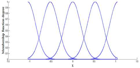
Fig.7. Membership function of
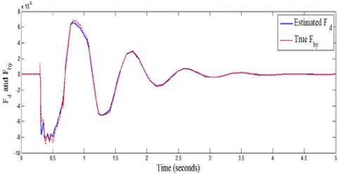
Fig.8. True and Estimated forces (case 1)
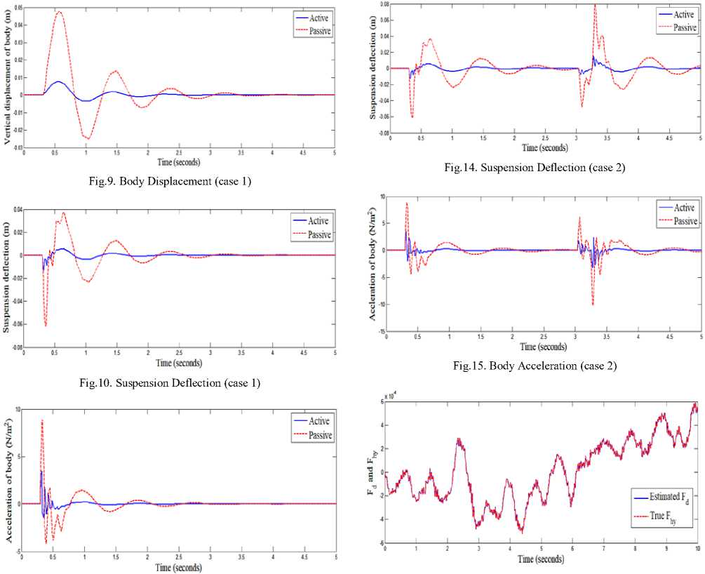
Fig.11. Body Acceleration (case 1)
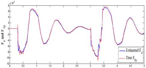
Fig.12. True and Estimated forces (case 2)
Fig.16. True and Estimated forces (case 3)
Time (seconds)
Fig.17. Body Displacement (case 3)
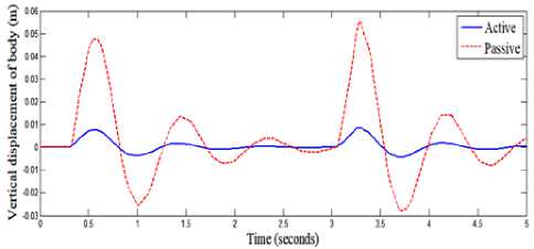
Fig.13. Body Displacement (case 2)
Time (seconds)
Fig.18. Suspension Deflection (case 3)
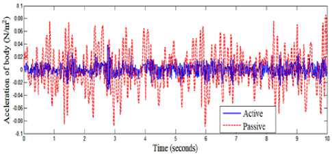
Fig.19. Body Acceleration (case 3)
-
VII. Conclusion
The paper presents a proposed control scheme that combines fuzzy sliding mode with PID controller tuned with ABC algorithm for the quarter vehicle active suspension system. The aim of the proposed controller was to improve the comfortable driving with an acceptable road holding of the vehicle and particularly to limit the vibration of the vehicle body. The parameters of the designed controller have been optimized by using Artificial Bee Colony algorithm.
Different cases have been considered. It was found from testing that a good drive comfort improvement has been accomplished by the proposed control scheme for various road profiles. Furthermore, it is seen that the new control scheme reduces body displacement and suspension deflection to very small values when compared with passive suspension system. Also the body acceleration is sufficiently reduced by the proposed control scheme. The obtained results show that the controlled active suspension system responses have been improved by approximately 90% when compared with passive suspension system.
References Fuzzy Sliding Mode Control Scheme for Vehicle Active Suspension System Optimized by ABC Algorithm
- P. Dowds, and A. O'Dwyer, “Modelling and control of a suspension system for vehicle applications”, 2005. Proceedings of the 4th Wismarer Automatisierungssymposium 2005, Wismar, Germany.
- E. Alvarez-Sánchez, “A quarter-car suspension system: car body mass estimator and sliding mode control”, Procedia Technology, 2013. 7: p. 208-214.
- AENS Ahmed, and et al., “PID controller of active suspension system for a quarter car model”, International Journal of Advances in Engineering & Technology, 2015. 8 6: p. 899.
- A. Agharkakli, G. S. Sabet, and A. Barouz, “Simulation and analysis of passive and active suspension system using quarter car model for different road profile”, International Journal of Engineering Trends and Technology, 2012. 3 5: p. 636-644.
- S. I. Son, and C. Isik, “Application of fuzzy logic control to an automotive active suspension system”, in Fuzzy Systems, 1996., Proceedings of the Fifth IEEE International Conference on. 1996. IEEE.
- R. Kothandaraman, and L. Ponnusamy, “PSO tuned adaptive neuro-fuzzy controller for vehicle suspension systems”, Journal of advances in information technology, 2012. 3 1: p. 57-63.
- W. H. Al-Mutar and T. Y. Abdalla , “Quarter Car Active Suspension System Control Using PID Controller tuned by PSO”, Iraqi Journal for Electrical And Electronic Engineering, 2015. 11 2: p. 151-158.
- A. A. Aldair, T. Y. Abdalla , and E. B. Alsaedee, “Design of1PID Controller using ABC for Full Vehicle Nonlinear Active Suspension System with Passenger Seat”, IJCA, 2017. 8: p. 9.
- M. Farahmand, C. Lucas, and M. Yazdanpanah, “Design of Fuzzy Logic and Optimal Control to an Automative Active Suspension system”, in Control and Automation, 2003. ICCA'03. Proceedings. 4th International Conference on. 2003. IEEE.
- W. H. Al-Mutar and T. Y. Abdalla, “Quarter Car Active Suspension System Control using Fuzzy Controller tuned by PSO”, International Journal of Computer Applications, 2015. 127 2.
- Y. M. Sam, J. H. Osman, and M. R. A. Ghani, “A class of proportional-integral sliding mode control with application to active suspension system”, Systems & control letters, 2004. 51 3-4: p. 217-223.
- T. Yoshimura, and et al., “Construction of an active suspension system of a quarter car model using the concept of sliding mode control”, Journal of Sound and Vibration, 2001. 239 2: p. 187-199.
- Y. Sam and J. H. S. Osman, “Sliding mode control of a hydraulically actuated active suspension”, Jurnal Teknologi, 2006. 44: p. 37-48
- F. Zhu, A. Winfield, and C. Melhuish, “Fuzzy sliding mode control for discrete nonlinear systems”, Transactions of China Automation Society, 2003. 22 2.
- I. Eksin, M. Guzelkaya, and S. Tokat, “Sliding surface slope adjustment in fuzzy sliding mode controller”, in Mediterranean Conference. 2002.
- S. J. Huang and H. Y. Chen, “Adaptive sliding controller with self-tuning fuzzy compensation for vehicle suspension control”, Mechatronics, 2006. 16 10: p. 607-622.
- F. Zhao, and et al., “Adaptive neural-sliding mode control of active suspension system for camera stabilization”, Shock and Vibration, 2015. 2015.
- M. M. Ma and H. Chen, “Disturbance attenuation control of active suspension with non-linear actuator dynamics”, IET control theory & applications, 2011. 5 1: p. 112-122.
- V. I. Utkin, “Sliding modes and their applications in variable structure systems”, Mir, Moscow, 1978.
- K. Rajeswari and P. Lakshmi, “GA tuned distance based fuzzy sliding mode controller for vehicle suspension systems”, International Journal of Engineering and Technology, 2008. 5 1: p. 36-47.
- SHYU KUOKAI and JUNJUH YAN, “Robust stability of uncertain time-delay systems and its stabilization by variable structure control”, International Journal of Control, 1993. 57 1: p. 237-246.
- T. Y. Abdalla , H. A. Hairik, and A. M. Dakhil , “Minimization of torque ripple in DTC of induction motor using fuzzy mode duty cycle controller”, Energy, Power and Control (EPC-IQ), 1st International Conference on, IEEE 2010.
- T. Y. Abdalla, A. A. Abed, and A. A. Ahmed, “Mobile robot navigation using PSO-optimized fuzzy artificial potential field with fuzzy control”, Journal of Intelligent & Fuzzy Systems, vol. 32, No.6,. 2017.
- Z. T. Allawi and Turki Y. Abdalla, “An Optimal Defuzzification Method for Interval Type-2 Fuzzy Logic Control Scheme”, IEEE science and information conference, 2015, London.
- Z. T. Allawi and Turki Y. Abdalla, “PSO-optimized type-2 fuzzy logic controller for navigation of multiple mobile robots”, IEEE 19th International Conference On Methods and Models in Automation and Robotics (MMAR), 2014.
- J. A. Dickerson and B. Kosko, “Fuzzy function approximation with ellipsoidal rules”, IEEE Trans. Syst., Man, Cybern., vol. 24, pp. 542–560, 1996.
- M. I. Hamzah and Turki Y. Abdalla, “Mobile Robot Navigation using Fuzzy Logic and Wavelet Network”, International Journal of Robotics and Automation, Vol. 3, Nol. 3, 2014.
- J. Liu, “Sliding Mode Control Using MATLAB”, 2017: Academic Press.
- B. Chen, and et al., “Direct adaptive fuzzy control of nonlinear strict-feedback systems”, Automatica, 2009. 45 6: p. 1530-1535.
- S. Pareek, M. Kishnani, and R. Gupta, “Application of artificial bee colony optimization for optimal PID tuning”, in Advances in Engineering and Technology Research (ICAETR), 2014 International Conference on. 2014. IEEE.
- M. H. A. Talib and I. Z. M. Darns, “Self-tuning PID controller for active suspension system with hydraulic actuator”, in Computers & Informatics (ISCI), 2013 IEEE Symposium on. 2013. IEEE.
- G. Yan and C. Li, “An effective refinement artificial bee colony optimization algorithm based on chaotic search and application for pid control tuning”, Journal of Computational Information Systems, 2011. 7 9: p. 3309-3316.
- M. E. El-Telbany, “Tuning PID controller for DC motor: An artificial bees optimization approach”, International Journal of Computer Applications, 2013. 77 15.
- D. Karaboga, “An idea based on honey bee swarm for numerical optimization”, in Secondary based. 2005, Technical report-tr06, Erciyes university, engineering faculty, computer
- Y. Sonmez, and et al., “Improvement of Buck Converter Performance Using Artificial Bee Colony Optimized-PID Controller”, Journal of Automation and Control Engineering, 2015. 3 4: p. 304-310.
- D. Rosheila, “Modeling and control of active suspension for a full car model”, Master Dissertation. Malaysia Technology University 2008.
- Sun Woo Kang, J. S. Kim, and Gi Woo Kim, “Random Road Measurement Roughness based on Gauss-Markov Process”, Transactions of the Korean Society for Noise and Vibration Engineering. Vol.28, 2018, 432-439.
