GPS based Advanced Vehicle Tracking and Vehicle Control System
Author: Mashood Mukhtar
Journal: International Journal of Intelligent Systems and Applications(IJISA) @ijisa
Article in issue: 3 vol.7, 2015.
Free access
Security systems and navigators have always been a necessity of human’s life. The developments of advanced electronics have brought revolutionary changes in these fields. In this paper, we will present a vehicle tracking system that employs a GPS module and a GSM modem to find the location of a vehicle and offers a range of control features. To complete the design successfully, a GPS unit, two relays, a GSM Modem and two MCU units are used. There are five features introduced in the project. The aim of this project is to remotely track a vehicle’s location, remotely switch ON and OFF the vehicle’s ignition system and remotely lock and unlock the doors of the vehicle. An SMS message is sent to the tracking system and the system responds to the users request by performing appropriate actions. Short text messages are assigned to each of these features. A webpage is specifically designed to view the vehicle’s location on Google maps. By using relay based control concept introduced in this paper, number of control features such as turning heater on/off, radio on/off etc. can be implemented in the same fashion.
Tracking, GSM, GPS, Vehicle Tracking, Google Map, Google Tracking, Vehicle Control
Short address: https://sciup.org/15010662
IDR: 15010662
Text of the scientific article GPS based Advanced Vehicle Tracking and Vehicle Control System
Published Online February 2015 in MECS
The vehicle tracking system is an electronic device that tracks the vehicle’s location. Most of the tracking systems use GPS module to locate the vehicle’s position [1].Many systems also combines communication components such as satellite transmitters to communicate the vehicle’s location to a remote user [2]. Google maps are used to view the vehicle’s location. The design of the tracking system is divided into three parts; basic design, intermediate design and an advance Design. The basic design of the vehicle tracking system consists of a GSM module, a GPS module, a MCU (ATMEL), a Relay circuit and a LCD. The user sends SMS and the system responds to the user’s request by providing the coordinates of a location in accordance to the requirements of mobile phone users through the GPRS network. The intermediate and advance design is an improvement of the basic design. There are five features introduced in the project. SMS codes are specifically assigned to each of these features. For example, if the user sends ‘555’ to the tracking system. The GSM modem will receive the SMS and transmit to the MCU unit, where the SMS code will be compared against the codes stored in the library. In this project, the code ’555’ is assigned to find the location of a vehicle. So, the MCU will get the location from the GPS module and reply back to the user with the location coordinates (i.e. Longitude and Latitude). These coordinates can be used to view the location of a vehicle on Google maps. The vehicle tracking system presented in this paper comprises of a cost effective and special tracking technology. It offers an advanced tracking and a variety of control features that facilitate the monitoring and clever control of the vehicle. The tracking systems are not only bounded to shipping industry and fleet tracking but also used in cars as a theft prevention tool.
This paper provides an overview of the background research related to vehicle tracking and control systems, component’s choice and full development process of the tracking system. The paper is divided in five main sections: related research, choice of components, design of a system, simulation of designs and implementation process. In the related research section, we will outline the research carried out so far. Then, we will discuss the components used. The design section will focus the software and hardware design process. The assembly of components will be discussed in the implementation section. Finally, the implementation process section will include the software simulations and images of the hardware in working condition.
-
II. Related Research
Number of papers has been published on the development of vehicle tracking system using GPS and GSM Modem [3],[4],[5],[6],[7],[8],[9],[10],[11],[12],[13] and [14]. In [15], differential GPS algorithm that is capable of providing real-time near PPP service is presented. In [16], error sources in GPS measurement are calculated. In [17], vehicular navigation application is presented. A web application and a mobile application related to vehicle tracking are presented in [18]. In [19] safety challenges related to tracking system and GPS are discussed in great detail. A novel method of vehicle tracking is presented in [20] using wireless sensor technology, passive sensors [21], android based tracking [22], self-power tracking system [23] and tracking system based on cloud computing infrastructure [24]. A vehicle tracking system based on color histogram distance and binary information is implemented [25]. In [26] development of real-time visual tracking system for vehicle safety applications is discussed and the concept of focus of expansion (FOE) is introduced. A low cost real time tracking system that provides accurate localizations of the tracked vehicle is presented in [27].Vehicle tracking coupled with vehicle registration number recognition is introduced in [28]. Following huge demand of accurate vehicle tracking systems, researchers proposed number of novel methods [29], [30], [18] to improve the accuracy of tracking systems.
-
III. Choice of Components
-
A. The Microcontroller unit (MCU)
There are two ways to control an electronic circuit either using: Microprocessor or MCU. The Microprocessors are usually referred to as generalpurpose microprocessors because they do not contain RAM, ROM and I/O ports. So, system designers have to add an external RAM, ROM and I/O ports to make a system functional. Addition of these components will make the system bulkier and much more expensive. The advantage of using microprocessor is that the designer can decide the amount of RAM, ROM and I/O ports needed to accomplish a task.
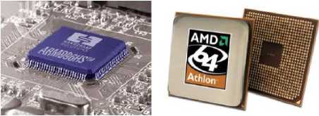
(a) (b)
Fig. 1. (a) Microprocessor embedded on a board [31] (b) AMD Microprocessor [32].
However, MCUs have a CPU in addition to the fixed amount of RAM, ROM and I/O ports, which are embedded on a chip with support functions such as a crystal oscillator, timers and serial or analog input output (I/O) [33]. The MCUs are designed for embedded applications and can be used in remote controls, power tools, toys and other appliances. Invention of MCUs has reduced the size and cost of designs. MCUs are suitable where cost and space are critical. There are four types of MCUs (8 bit): 8051 family, PIC, Zilog and Freescale. The MCU families are not compatible with each other, which means, if we write a code for 8051 MCU it will not work on PIC MCU. This is mainly due to different instructions and registers set in each MCU.
To choose among these MCUs, there are specific criteria set for designers: MCU should meet the task at hand efficiently and cost effectively [34]. Software development tools such as compilers, assemblers and debuggers should be available in the market [34]. Wide availability and reliable sources of the MCU used. Designer should also consider the speed, Packaging, power consumption, the amount of RAM, ROM on chip and cost per unit [35].
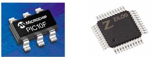
(a)
(b)
Fig. 3. (a) A PIC Microcontroller [36], (b) A Zilog Microcontroller [37].
-
B. GSM Modem
A GSM module is a second generation digital mobile cellular technology, which covers a fairly broad geographic area. This offers customized travel, financial, reference and commercial information to the users [38]. It can operate in 400MHz, 900MHz and 1800MHz frequency bands. The GSM modem can accept a SIM card just like a mobile phone and operate on a subscription to a network of mobile data transfer. The GSM Modem supports three types of services namely bearer or data services, supplementary services, and telecommunication services. A typical GSM picture is given below:
(a)
(b)
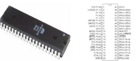
Fig. 2. (a) 8051 Family Microcontroller [34], (b) A Microcontroller pin description [35].
C. GPS Modules
The first GPS (navigation system) was designed by Honda in 1983 [40]. Pioneer claims to be the first with a GPS-based auto navigation system, in 1990 [41]. Magellan claims to have created the first GPS-based vehicle navigation system in the U.S in 1995 [42].
Each GPS (satellite) transmits data that indicates the current time and its location. It transmits signals to a GPS receiver. This receiver requires an unobstructed view of the sky, so they can only be used effectively outdoors. The step by step operation of the GPS can be seen in figure 5.
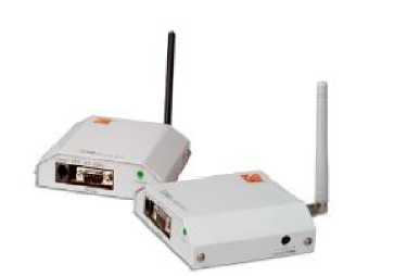
Fig. 4. A GSM Modem (Global System for Mobile Communications)
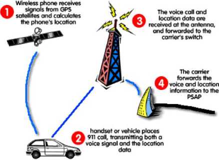
Fig. 5.Various Steps of GPS operations [43].
D. Types of Tracking
There are four types of tracking: direction finding tracking, The LORAN’s tracking technique, signpost tracking and GPS based tracking. In direct finding tracking, cellular or PCS wireless systems uses this tracking technique to calculate the bearing from two fixed sites to the mobile. A triangle is created with endpoints at the two fixed points and trigonometry tells the location of a mobile transmitter [44].
Loran tracking technique is used to find the location of an object by using the time difference between receptions of radio signals from two or higher power fixed transmitters. The system consists of a receiver, and data interface box/modem connected to a separate two-way radio. Based on LORAN signal, the receiver calculates the longitude and latitude in degrees and plotted the location on a map. The LORAN’s tracking system has limited resolution, which makes the system impractical. Signpost systems are mostly used in rail lines. A transponder is polled as the train traverses its route. As train pass, it receives handshake from the signpost transmitter. A transmitter on the mobile would report passing the signpost to a system controller [45]. GPS based tracking is used to locate the position of a vehicle. It is a satellite-based navigation system that was developed by the U.S. Department of Defence (DoD) in the early 1970s [46]. Initially, GPS was developed as a military system to fulfil U.S. military needs. However, it was later made available to the civilians, and is now a dual-use system that can be accessed by both military and civilian users.
-
IV. Design of a System
In order to complete the project successfully, number of steps are followed. A comprehensive review of development process is shown in the “Fig. 6”.
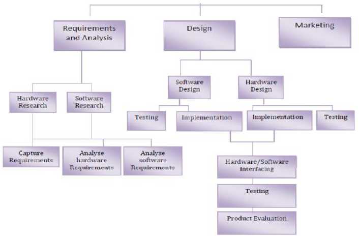
Fig. 6. Development process of our product.
The design is divided into three parts: Basic Design (Original Aim of the project), Intermediate Design (Additional bit) and Advance Design (Additional bit).
There are three ways to operate the vehicle tracking system: Send request via mobile (Basic design), Send request via computer (Intermediate design) and Auto request (Advance design). As shown in the figure 7, there are three ways to send a SMS to the GSM Modem. The basic design will allow the users to send/receive a SMS message using a mobile phone. A SMS can be sent directly from computer using the intermediate design.
The advance design will allow the user to get the locations of a tracking vehicle without entering any command or sending codes to the device. It does the operation automatically. Once the GSM modem receives the user request, it forwards the request to the MCU unit, where it will be processed by comparing the code against already stored codes in the MCU’s memory. If the user has sent ‘111’, ‘222’, ‘333’, ‘444’ and ‘555’ code then the device would respond ‘Engine kill’, ’Engine release’,’ Door open’, ‘Door close’ and ‘Get location’ respectively.
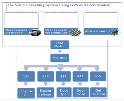
Fig. 7. Operations of a vehicle tracking system.
-
A. Basic design
Basic design will allow users to send a SMS from a mobile phone to the tracking system and get the response back via SMS. The user will input the longitude and latitude received in a SMS to the designed web page to view the vehicle’s location on Google maps. The basic design of the vehicle tracking system consists of a GSM module, a GPS module, a MCU (ATMEL), a relay circuit and a LCD. The figure shown below represents the block diagram of the components used in order to build the vehicle tracking system.
First of all, the system will be initialized by sending a SMS to the GSM Modem. The GSM modem will read the SMS and transmit to the MCU unit. The MCU unit will process the request by first checking the mobile number against the stored numbers in its library. If a mobile number matches to the MCU library number, the user request will be further processed by first comparing the request code with the stored codes and then taking the appropriate actions. For example, if the user sends a code ‘555’ to the GSM then the MCU unit will get the coordinates (Longitude and Latitude) from the GPS receiver. However, if the code is ‘111’,’222’,’333’ and ‘444’, the relay circuit will be operated to lock/unlock the doors and switch ON/OFF the ignition system of the vehicle respectively. Finally, the results will be displayed on the LCD as well as on the computer. The flowchart of basic design is shown in “Fig. 8”.
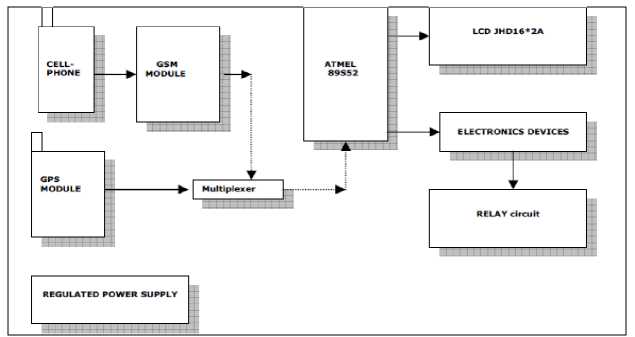
Fig. 8. Block diagram of the project.
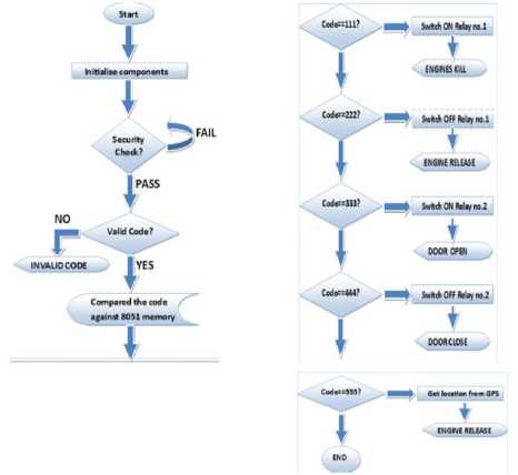
Fig. 9. Flowchart of basic design.
B. Intermediate design
By using the intermediate design, the user can send a SMS from computer directly to the tracking system. The user will copy (rather than typing or inputting) the longitude and latitude to the designed web page to view the vehicle’s location on Google maps. The user can send a SMS to the tracking device either by using SMS gateway software such as i-chat or by connecting the mobile with computer. This connection could be wired or wireless i.e. Bluetooth. Every mobile company provides the software with their mobile which enables users to manage their phones. For example Nokia offers software called Nokia PC Suite. This allows users to establish an interface between Nokia mobile phones and the computer. It can be used to transfer music, photos and other applications. In the vehicle tracking system, we will connect a mobile to the computer using Nokia PC Suite. This will enable user to send/receive SMS to/from the
device. This method of connecting mobile does not require any circuitry hence, reducing the cost and complexity of the project. The only difference between the basic design and the intermediate design is sending method. In the basic design, we have sent a SMS from a mobile phone but the intermediate design allow the users to send a SMS to the device using Nokia PC Suite.
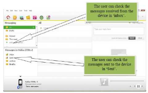
Fig.10. Nokia PC Suite software.
-
C. Advance design
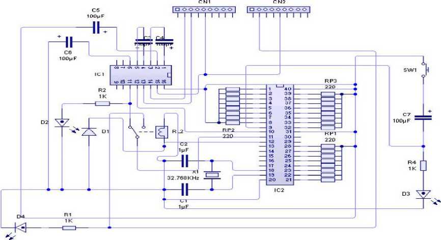
Fig. 11. Circuit diagram of an advance design.
First of all, the advance system will be initialized by setting the mode and the timers. Then, the device (The advance design) will send request to the tracking system (The basic design) automatically. After that the tracking system (The basic design) will perform a security check followed by valid code check. If both condition are true (PASS), then the GPS will operate and the tracking system will respond to the user request by sending a SMS. The device (The advance design) will read the SMS and translate the coordinates.
-
V. Simulation of Designs
Although there are varieties of software packages, which can be used to simulate the circuit; the most commonly used are the circuit wizard and the PCB wizard. In order to test circuit, I have used the Proteus design suite (software). The Proteus design suite (software) is used for the electronic circuit simulation, the schematic capture and the printed circuit board (PCB) design. By combining ISIS schematic capture and ARES PCB layout the Proteus design suite (software) provides a powerful, an integrated and easy to use suite of tools for professional PCB design. The Proteus can be used to design a complex circuit for the simulation and the printed circuit board (PCB) layout. Below given figures shows the welcome screen of the Proteus software.
The Proteus software allows the users to simulate the circuit connections and find out the expected results (In real times). I have simulated the Circuit using the Proteus and got the results as shown in “Fig. 13” for the basic design:
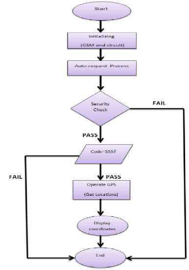
Fig. 12. Flowchart of an advance design.
The advance design was also designed and simulated in the Proteus software. This design will allow the users to locate the vehicle’s location without inputting coordinates in mapping software.
The hardware as shown in “Fig. 14” will be connected to computer straight way using MAX232 to show location without inputting coordinates to Google earth. When we simulate the circuit, the virtual terminal shows the AT commands. These AT commands are used to communicate between the device and the computer. Simulation results from an advance design are shown in figure 13.
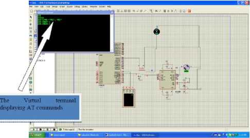
Fig. 15. Execution of AT commands in virtual terminal.
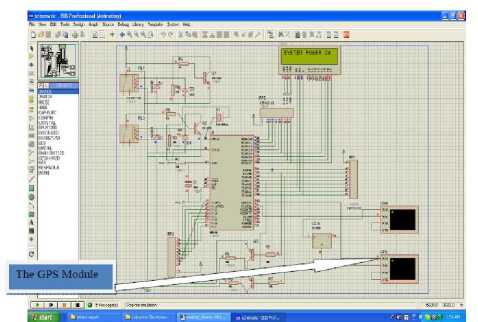
Fig.13. System is powered ‘ON’.
-
VI. Implementation Process
In the implementation section, we will discuss the steps that were followed to build the vehicle tracking system. Furthermore, this chapter will also focus the reasons behind choosing specific components used in the tracking system. Following steps were taken to build the system: Selecting the right component, choosing the programming language and appropriate software to simulate the design.
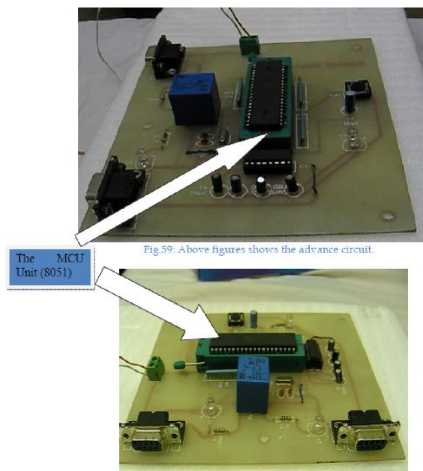
Fig. 14. PCB circuit of an advance design.
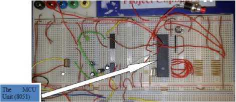
Fig. 16. Prototype of a circuit.
-
A. Selecting the right components
An extensive research has been carried out to find the right components to build the vehicle tracking system. Some of the components used are listed below with a brief description.
The MCU Unit
Each MCU has a unique functionality, which can make them more appropriate for use over the rest. For the basic design and advance design, AT89S52 MCU from 8051 family was used. The AT89S52 is a low-power, high-performance CMOS 8-bit MCU with 8K bytes of insystem programmable flash memory.
In order to free users from the hassle of inputting the longitude (angular distance) and latitude (angular distance), the advance design would require another MCU, which will be connected to computer. This MCU will allow the users to find a precise location directly on the computer without inputting any information. The MCU (AT89S51) has 4 input output ports, which are more than enough to accomplish the tasks of this project. One port will be used for serial communication other will be free for any improvement of the system.
Liquid Crystal Diode (LCD)
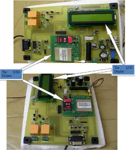
Fig. 17. PCB Board pointing LCD and GSM Modem.
Oscillator
The speed of the MCU depends on the frequency of the oscillator. There are oscillators of different frequencies available. An oscillator of 11.0592 MHz frequency is chosen. Some of the components (i.e. oscillators) used in this project were available in the local lab and simply chosen because of their urgent availability. The MAX232 is used to connect the MCU with RS232, which fits into the serial port of the computer.
The GSM
A GSM modem used in this project is SIMCOM SIM 300DZ. The GSM modem (SIM 300DZ) is tri-band GPRS/GSM device. This can operate over 900, 1800 and
1900 MHz bands. The SIM 300DZ provides RF antenna interface. With the charge circuit integrated inside the GSM module (SIM 300DZ), it is very suitable for the battery power application. With a dimension of 33 x 33 x 3 mm, it can fit in almost all the wireless applications. The SIM card is inserted for the purpose of the user identification in the GSM module.
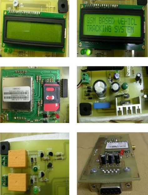
Fig. 18. Different component of a circuit.
The GPS
One of the most important tasks in the project is designing and implementation of the GPS receiver circuit. I have used M-89 GPS receiver. The receiver has 30 pins. The GPS antenna is used to catch the signals from the satellite. The MCU reads the receiver’s data. The GPS outdoor antenna tuned to receive 1575.42 MHz L1 band satellite transmissions. The received signals are passed through a narrow band-pass filter and a pre-amplifier within the antenna. The active antenna circuitry provides 30 dB of gain and requires +5 VDC at 27 milliamps (provided by a Spectra com GPS receiver over the antenna coax). There are 12 pins on the PCB board. First 2 pins (Count from left; top to bottom) and the pins from 7 to 12 are grounded. Pin no 3 is used for LED. The LED blinks, when the GPS receive the data form the satellites. Pin no 4 is use for TX (Transmission) and pin no 6 is connected to +5V.
-
B. Choosing the right programming language
Although, there are lot of programming languages that could be used to program the MCU, the most common ones are C programming language and Assembly language. The programs written in the assembly language can execute faster, while programs written in the C programming are easier to develop and maintain. I have used the assembly language in 2nd year and 3rd year of my engineering projects. So, I have better command and knowledge of the assembly language. Therefore; assembly language was chosen to build the vehicle tracking system.
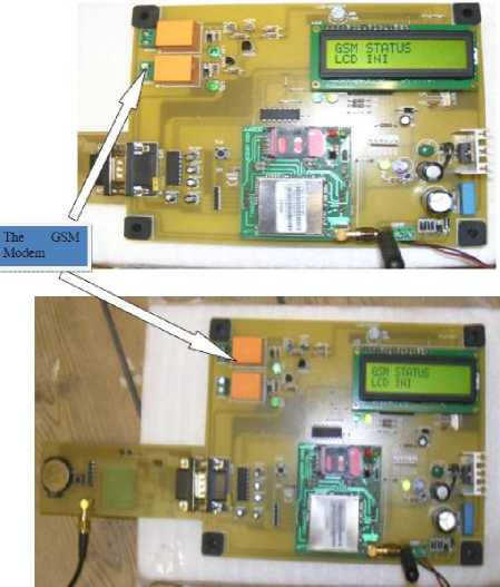
Fig.19. GSM module pointed by arrows.
Web Page to track and control vehicle
HTML language is used to develop the webpage needed to display the location of a vehicle. The Google maps are embedded in my webpage so, that the user can input the longitude and latitude to view the location.
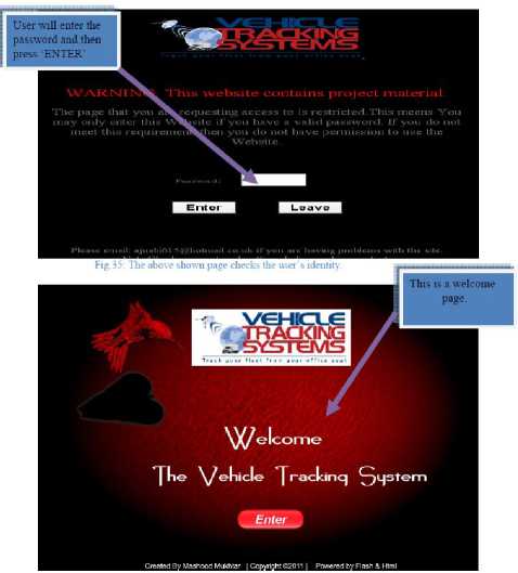
Fig. 20. Webpage of vehicle tracking system.
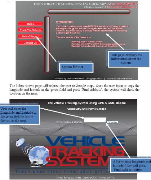
Fig. 21. Control Panel of the webpage.
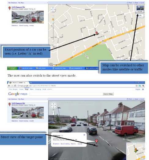
Fig. 22. Vehicle located using our tracking system
-
C. Appropriate software to simulate my design
Although there are varieties of software packages, which can be used to simulate the circuit; the most commonly used are the circuit wizard and the PCB wizard. In order to test the circuit, Proteus design suite (software) is used. It is very powerful tool for the electronic circuit simulation, the schematic capture and the printed circuit board (PCB) design. By combining ISIS schematic capture and ARES PCB layout the Proteus design suite (software) provides an integrated and easy to use suite of tools for professional PCB design. The Proteus can be used to design a complex circuit for the simulation and the printed circuit board (PCB) layout.
Step 2: we will use the following code to display the welcome message on the LCD:
Fig. 23. (a) Proteus Software picture [46], (b) Proteus ISIS Schematic captures [47].
LCALL LCD_LENE2
DB "TRACKING SYSTEM ",0
LCALL DELAYS
LCALL LCD_LINE1
DB * ",0
LCALL LCD.LINE2
LCALL DELAY3
LCALL LCD.LINE2
DB "LCD INI ’,0
‘CLR* command will clear the LCD and then print the welcome message. The message would be displayed in delays.
VII. Conclusion
The vehicle tracking system presented in this paper can be used for positioning and navigating the vehicle with an accuracy of 10 m. The positioning is done in the form of latitude and longitude along with the exact location of the place, by making use of Google maps. The system tracks the location of a particular vehicle on the user’s request and responds to the user via SMS. The received SMS contains longitude and latitude that is used to locate the vehicle on the Google maps. The vehicle tracking system allows a user to: remotely switch ON the vehicle’s ignition system, remotely switch OFF the vehicle’s ignition system, remotely lock the doors of the vehicle, remotely unlock the doors of the vehicle, and remotely track a vehicle’s location. Some changes were made in which most notable change was alteration of the tracking methodology (i.e. Access to 32 channels of satellites instead of 3). The vehicle tracking system was built successfully. However, the vehicle tracking system could be made more robust by using more accurate GPS unit.
Step 3: The following code will be used to set the timer of GSM. The GPS and relays will be set and the system will be switched ON:
GET_CORDINATE:
DB "GPS DATA..",0
START: ACALL DELAY3
LJMP DO_AG ;
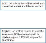
Before starting GSM, timer, mode and baud rate will be set.
Appendix
Step 4: After switching GPS, GSM and relays ON, the system will look for any received messages, If any SMS found. Microcontroller will first verify the user number to confirm that the user has permission to use the system. The following code mil be used to verify the user:
A. Pseudo Code (Basic Design)
Step 1: First of all, we will initialize the variables and define the timer as shown below;
MOV R0.S50H
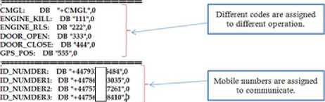
MOV DPTR,*1D_NUMDER
,-COMPARE SENDER NUMBER
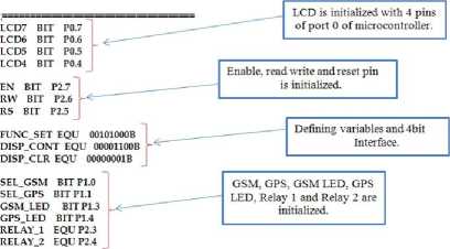
CR EQU 13
LF EQU 10
DISCART EQU22H
BUFF EQU 23H
TEMPI EQU 24H
TEMP2 EQU 25H
RX_CNT1 EQU26H
RX_CNT2 EQU27H GSM_BUFF EQU 60H OK BIT OH
LCALL COMF1
JNB OK,IDV_L01
ACALL CHECK-CODE
RET
IDV-L01;
MOV R0,*50H
MOV DPTR,*ID_NUMDER1
LCALL COMF1
MOV DPTR,«ID_NUMDER2
LCALL COMF1
JNB OK,IDV_L04
ACALL CHECK-CODE
.-COMPARE SENDER NUMBER 1

Once the system receives SMS from user, Microcontroller will check the number with already stored ones to verify the user permission.
;COMPARE SENDER NUMBER2
LCALL COMF1
JNB OK,IDV_L05
ACALL CHECK-CODE
RET
LCALL LCD_PRINT
DB * INVALID NUMBER '0 LCALL DELAYS
RET
.COMPARE SENDER NUMBER?
;NO COMPARISION FOUND
ORG 0030H CLR PO.O CLR РОЛ CLR P0.2 CLR P0.3 MOV TMOD,#20H .TIMER 1MODE2 MOV SCON,#50H
Step 5: After verifying the user. System will compare the SMS received with the stores SMS to find out which operation should be performed.
CHECK-CODE: MOV RMGSXLBUFF
MOV DPTR,«ENGINE KILL ;COMPARE SMS WITH IDOL
LCALl COMF1
JNB OKJDX'.CODEl
LCALL SMSJD01
MOV DPTR,*ENG1NE_RLS COMPARE SMS WITH ID02
LCALL COMF1
JNB OK,tDV_CODE2
LCALL SMSJD02
1DV_CODE2: MOV RO.^GSM BLTF
MOV DPTR.SDOOROFFN .COMPARE SMS WITH ГГЮЗ
LCALL COMF1
JNB OK,IDV_CODE3
LCALL 5M5_TD03
MOV DPTR,ffDOOR„CLOSE COMPARE SMS WITH 1041
LCALL COMF1
JNB OK,IDV_CODE4
LCALL SMSJD04
IDV.CODE4: MOV RO,SGSM_BLTF
MOV DPTR,BGPS_POS COMP ARE SMS KITH tDOl
LCALL COMF1
JNB OK,IDV_CODE5
LCAL^ GET.CORDINATE
CLR GSM_LED
LCALL GSMJNI
LCALL SMS.1D05
MOV B,al6
MOV RO,»GSM_BUFF
LOOP; MOV A@R0
INC RO DJNZ ВДООР RET
Microcontroller will compare the SMS with store memory to find out which operation is requestedby user.
Microconi roller will compare rhe SMS with store memory to find out which operation is requested by user.
Check if there is any new message
■ - DISPLAY SENDER NUMBER----------------
LOOP1; MOV A.SR0
DJNZ ВДООР1
When sender sends a request this subroutine will display the sender's number on the LCD.
AC ALL SMSJNI
LCALL DELAY3
LCALL TX232
DB "ACCESS DE NIED",26,0
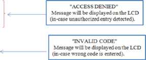
DB "INVALID CODE; PLEASE ENTER THE CORRECT CODE ",26,0 LJMP SMS-EXIT
’AT+CMGS-^O
К0Л5ОН
MOV A.8R0
LCALL TX
INC RO
MOV АЛ34
MOV A,SCR LCALL TX LCALL DELAYS
SMS. EXIT: MOV Brs2 LLOP: ACALL RX DJNZ B.LLOP
DELAY3 DELAYS
DB "SENT ",0
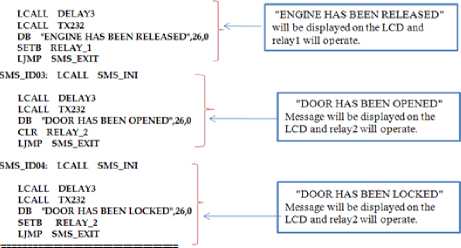
Before responding to user, the message “SENDING SMS" will appear. This is done by first clearing the LCD and then reading the values of SMS.
After respondingtouser, the message "SENT” will appear on LCD. This is done by first clearing the LCD and then printing the values of SMS.
Step 6: Different codes are assigned for different operation. System will perform the operation and display the operation on the LCD.
MOV B,#I6
MOV RO,#GSM_BUFE
DJNZ ВДООР2
This subroutine will display the recieved SMS.
END
LCALL DELAYS
LCALL TX232
DB "ENGINE HAS BEEN KILLED',26,0
CLR RELAY.I
"ENGINE HAS BEEN KILLED" will be displayed on the LCD and relayl will operate.
B. Pseudo Code (Advance Design)
Stepl: First of all, we will initialize the variables and AT commands used in the code. Then the timer and mood will be set to enable reception of serial data.
#include
sbitr-P3*2;
void send_GSM(un$igned char arrfl, unsigned int length,bitc);
void send.GSMafunsigned char anfl.unsigned bit length);
unsigned char chi;
unsigned char code аЩ-’АР;
unsigned char code ate[]=* ATEO’;
unsigned char code cmgfQ-*AT+CMGF-l*;
unsigned char code cmgs[]-"AT+CMGS-\’004479327864M\";
unsigned char code cmgsa0-"AT*CMGS-\'0M47S69103O35\*";
unsigned char code cpmsQ-’AT+CPMS-VinEWVMEV^
unsigned char code cmgrQ-'AT+CMGR-l';
unsigned char code cmgdQ-' AT+CMGD-l';
unsigned char code smsQ-'5K’;
AT commands are used to control GSM modem and send auto request.
unsigned char dat[30]; unsigned int Lj.k; void main(){
P2-0;
TMOD-Ox2ft
THl-OxFD;
SCON4JX50;
delay(lOO);
The timer and mode will be set up by enabling reception of serial data.
Step2: Now, The AT command will be sent to the GSM Modem with delays.
while(l){

delay<500);
send_GSM( send_GSM( delayilOO);
send_GSM(&cpms,17,0);
delay(lOO);
send_GSM(&cmgf,9,0);
delayflOO);
send_GSM(&cmgsa,243)k delav^lOO);
send_GSM(&sms^,l);
delay<500);
send_GSM(&cmgr,9,0);

Sending AT commands to GSM modem with delays.
void send_GSM(unsigned char arr[],unsigned int lengtibbit c)j unsigned int i;
for(i-Q;i while(TT—0); else inc ==l){ dela^lO); SBUF-Oxl A^code for ctrl+z while(TT—0); if(c—0){ delav(t); SBUF-0x0A;//code for line feed. while (П--0); SBUF-0x0D//code for cartage ruturn. whilefn—O); TI-0; Acknowledgment The work presented in this paper was done in 2011 as part of Master of Engineering final year project under the supervision of Professor Peter O' Hearn. The author wish to acknowledge sincere gratitude to project supervisor Professor Peter O’ Hearn for his encouragement and valuable support.
References GPS based Advanced Vehicle Tracking and Vehicle Control System
- A. EI-Rabbany, Introduction to GPS: The Global Positioning System, Norwood, MA: Artech House, 2006.
- M. Brain, "How Microcontroller Works," HowStuffWorks, a division of InfoSpace LLC, [Online]. Available: http://www.howstuffworks.com/microprocessor.[Accessed 10 12 2014].
- H. D. Pham, M. Drieberg and C. C. Nguyen, "Development of vehicle tracking system using GPS and GSM modem," in IEEE Conference on Open Systems (ICOS), Kuching , 2013.
- M. Ahmad Fuad and M. Drieberg, "Remote vehicle tracking system using GSM Modem and Google map," in IEEE Conference on Sustainable Utilization and Development in Engineering and Technology (CSUDET), Selangor , 2013.
- M. Parvez, K. Ahmed, Q. Mahfuz and M. Rahman, "A theoretical model of GSM network based vehicle tracking system," in International Conference on Electrical and Computer Engineering (ICECE), Dhaka, 2010.
- R.Ramani, S.Valarmathy, D. N.SuthanthiraVanitha, S.Selvaraju and M.Thiruppathi.R.Thangam, "Vehicle Tracking and Locking System Based on GSM and GPS," I.J. Intelligent Systems and Applications, vol. 09, pp. 89-93, August 2013.
- P. P. Wankhade and P. S. Dahad, "Real Time Vehicle Locking and Tracking System using GSM and GPS Technology-An Anti-theft System," International Journal of Technology And Engineering System(IJTES), vol. 2, no. 3, 2011.
- P. Verma and J. Bhatia, "Design and Development of GPS-GSM based Tracking System with Googlemap based Monitoring," International Journal of Computer Science, Engineering and Applications (IJCSEA), vol. 3, no. 2, June 2013.
- T. Le-Tien and V. Phung-The, "Routing and Tracking System for Mobile Vehicles in Large Area," Fifth IEEE International Symposium on Electronic Design, Test and Application, pp. 297-300, January 2010.
- P. Fleischer, A. Nelson, R. Sowah and A. Bremang, "Design and development of GPS/GSM based vehicle tracking and alert system for commercial inter-city buses," IEEE 4th International Conference on Adaptive Science & Technology (ICAST), October 2012.
- M. N. Ramadan, M. A. Al-Khedher and S. A. Al-Kheder, "Intelligent Anti-Theft and Tracking System for Automobile," International Journal of Machine Learning and Computing, vol. 2, no. 1, February 2012.
- D. A. Brown, "A Low Cost Vehicle Location and Tracking System," NAVSYS Corporation, pp. 516-523, 1992.
- M. A. Elahi, Y. A. Malkani and M. Fraz, "Design and implementation of real time vehicle tracking system," 2nd International Conference on Computer, Control and Communication, pp. 1-5, 2009.
- P. A. Okatan and A. Salih, "Micro-Controller based Vehicle Tracking System," IEEE, pp. 605-609, 2003.
- H.-W. Chen, Y.-T. Chiang, F.-R. Chang and H.-S. Wang, "Toward real-time precise point positioning: Differential GPS based on IGS ultra rapid product," in Proceedings of IEEE in SICE Annual Conference, 2010.
- P. Misra and P. Enge, "Global Positioning System: Signals, Measurements, and Performance," in Massachusetts, Ganga-Jamuna Press, 2001.
- M. Honda, M. Murata and Y. Mizukura, "GPS Precise Point Positioning Methods Using IGS Products for Vehicular Navigation Application," in International Joint Conference SICE-ICASE, Busan , October 2006.
- I. Almomani, N. Alkhalil, E. Ahmad and R. Jodeh, "Ubiquitous GPS vehicle tracking and management system," in IEEE Jordan Conference on Applied Electrical Engineering and Computing Technologies (AEECT), Amman , December 2011.
- Z. Constantinescu and M. Vladoiu, "Challenges in safety, security, and privacy in the development of vehicle tracking systems," in 17th International Conference System Theory, Control and Computing (ICSTCC) , Sinaia , October 2013.
- K. Aravind, T. Chakravarty, M. Chandra and P. Balamuralidhar, "On the architecture of vehicle tracking system using wireless sensor devices," in International Conference on Ultra Modern Telecommunications & Workshops ICUMT, St. Petersburg , October 2009.
- P. Choudhari, "Development of vehicle tracking system using passive sensor," in International Conference on Communication, Information & Computing Technology (ICCICT), 2012.
- A. Tahat, A. Said, F. Jaouni and W. Qadamani, "Android-based universal vehicle diagnostic and tracking system," in IEEE 16th International Symposium on Consumer Electronics, 2012.
- I. M. Tolentino and M. R. Talampas, "Design, development, and evaluation of a self-powered GPS tracking system for vehicle security," in IEEE Sensors, 2012.
- A. Alexe and R.Ezhilarasie, "Cloud Computing Based Vehicle Tracking Information Systems," IJCST, vol. 2, no. 1, March 2011.
- N. Zhang, Y. Feng and R. Ma, "The research and implementation of vehicle tracking system based on color histogram," in Second International Conference on Mechanic Automation and Control Engineering (MACE), Hohhot, July 2011.
- K.-T. Song and C.-C. Yang, "Front Vehicle Tracking Using Scene Analysis," in Proceedings of the IEEE International Conference on Mechatronics & Automation, 2005.
- W. El-Medany, A. Al-Omary, R. Al-Hakim, S. Al-Irhayim and M. Nusaif, "A Cost Effective Real-Time Tracking System Prototype Using Integrated GPS/GPRS Module," in 6th International Conference on In Wireless and Mobile Communications (ICWMC), 2010.
- H. Lee, D. Kim, D. Kim and S. Y. Bang, "Real-time automatic vehicle management system using vehicle tracking and car plate number identification," in International Conference on Multimedia and Expo. ICME ’03, 2003.
- A. Dewandaru, A. M. Said, A. N. Matori and U. T. Petronas, "A Novel Map-matching Algorithm to Improve Vehicle Tracking System Accuracy," 2007.
- G. Challita, S. Mousset, F. Nashashibi and A. Bensrhair, "An application of V2V communications : Cooperation of vehicles for a better car tracking using GPS and vision systems," in IEEE Vehicular Networking Conference (VNC), 2009.
- "The Microprocessors," Connect in, 08 February 2005 . [Online].Available:http://connect.in.com/microprocessor/photosmicroprocessor-916bf2805ceb0ac0.html. [Accessed 13 10 2013].
- M. Brain, "How Microprocessors Work," HowStuffWorks, a division of InfoSpace LLC, 2008. [Online]. Available: http://www.howstuffworks.com/microprocessor.htm/printable. [Accessed 10 12 2014].
- "Introduction, MCU," Astronomy pocket Pc Project, 2009. [Online].Available:http://astrosurf.com/astroenit/projets/astronomy_pocket_pc_en.
- "Introduction to Microcontrollers," Society of Robots, September 2005. [Online]. Available: http://www. societyofrobots.com/microcontroller_tutorial.shtml. [Accessed 12 12 2014].
- "The 8051 microcontroller architecture," Electronic and Electricity, February 2010. [Online]. Available: http://www.zonetronik.com/en/2010/01/the-8051-microcontroller-architecture. [Accessed 13 10 2010].
- "Microcontrollers or microprocessors," Techie’s digital points, June 2008. [Online]. Available: http://compuzer. blogspot. com /2008/02/which-one-is-boss-microprocessor-or.html. [Accessed 17 10 2010].
- "Integrated circuits (ICS)," Digi Key corporation, August 2005. [Online]. Available: http://parts.digikey.com /1/parts/index22820.html.
- M. A. Mazidi, J. Mazidi and R. McKinlay, The 8051 Microcontroller and Embedded Systems (2nd edition), Prentice Hall, 2006.
- " How GSM Modem Works," Broadband Suppliers, June 2007. [Online]. Available: http://www.broadbandsuppliers. co.uk/uk-isp/how-gsm-modem-works/.
- J. seahi, "Automotive Navigation System," Dec 2002. [Online]. Available: http://www.streetdirectory.com /etoday/automotive-gps-navigation-system-caeae.html. [Accessed 29 10 2010].
- N. JDR, "Pioneer Corporation," wikipedia.org, March 2008. [Online]. Available: http://en. wikipedia.org/wiki/Pioneer_Corporation.
- I. Jaguar, "Car Navigation System wiki," December 2002. [Online].Available: http://car-navigation-system. software.informer.com/wiki/.
- J. Gult, "The GPS Guide," August 2010. [Online]. Available: http://www.gpstrafficguide.com/wp-content/ uploads/2009/10/gps_traffic.gif.
- W. RAD, "WD-3300 High Performance Portable Direction Finding System,," September 2009. [Online]. Available: http://www.winradio.com/home/wd3300.htm.
- "Solar power and RFID tracking," Textually, November 2007. [Online]. Available:http://www.textually.org/ picturephoning/archives/2007/11/018015.htm.
- "Live GPS Vehicle Tracking System," YouTube, November 2007. [Online]. Available: http://www. youtube.com/watch?v=t6FrVBol9cU.
- "Proteus professional 7.7 sp," Hune 2003. [Online]. Available: http://efitsoftware.com/software/2811-proteus-professional-7.7-sp2.html.
- "multiplexer circuit," Digi Key corporation, August 2005. [Online]. Available: http://parts.digikey.com/ 1/parts/index22820.html.
