Hardware-in-the-loop of Simulation for a Hydraulic Antilock Brake System

Author: Ayman A. Aly
Journal: International Journal of Intelligent Systems and Applications(IJISA) @ijisa
Article in issue: 2 vol.5, 2013.
Free access
Hardware-In-the-Loop (HIL) of simulation policy is used as a rapid and economical tool for developing automotive systems effectively and for dangerous situations tests such as extreme road conditions or high travelling speeds. A method for building a HIL of simulation a hydraulic Antilock Braking System (ABS) based on MATLAB/Simulink is presented in this paper. The system is implemented for research purposes as well as for the application in educational process. It can help the user heightening the efficiency when developing the electronic device. Also, the system can be used as teaching demo software. Experiment tests of HIL scheme were carried to ensure the feasibility and effectiveness of the system.
Hardware-in-the-loop, Simulink, ABS, Hydraulic
Short address: https://sciup.org/15010370
IDR: 15010370
Text of the scientific article Hardware-in-the-loop of Simulation for a Hydraulic Antilock Brake System
Published Online January 2013 in MECS
The reason for the development of antilock brake systems (ABS) is in essence very simple. Under brake, if one or more of a vehicle’s wheels lock (begins to skid) then this has a number of consequences such as:
-
a) Braking distance increases.
-
b) Steering control is lost.
-
c) Tire wear will be abnormal.
The obvious consequence is that an accident is far more likely to occur. ABS is recognized as an important contribution to road safety as it is designed to keep a vehicle steerable and stable during heavy braking moments by preventing wheel lock. It is well known that wheels will slip and lockup during severe braking or when braking on a slippery (wet, icy, etc.) road surface. This usually causes a long stopping distance and sometimes the vehicle will lose steering stability [1-5]. The objective of ABS is to manipulate the wheel slip so that a maximum friction is obtained and the steering stability (also known as the lateral stability) is maintained. That is, to make the vehicle stop in the shortest distance possible while maintaining the directional control. The ideal goal for the control design is to regulate the wheel velocity. The technologies of ABS are also applied in traction control system (TCS) and vehicle dynamic stability control (VDSC) [6].
To meet the need of the researches, we built the HIL Simulator system for ABS. Though it is cheap, the simulating result lies on the quality of the model. Furthermore, in real world, because of the complexity of the physical system, it is difficult to build the model. Moreover, vehicle test is affected by many factors, such as hardware and environment condition, and difficult to simulate some limit conditions, also, test is expensive. So it can’t be used in all fields. Hardware-in the-loop Simulator can get over the shortage [7-10]. With the help of this system, you can heighten the efficiency when you develop electronic devices. It can cut down the tests on vehicles. Also, it can be used as teaching demo software.
In section 2, the HIL simulation is illustrated. While in section3, the experimental results are shown. Finally the conclusions are given.
-
II. Hardware-in-the-loop of Simulation
-
2.1 Vehicle and Road Model
This section presents the hardware-in-the-loop experimental method. Fig. 1 shows the hardware and software parts used in HIL experiments. The hardware comprises of a brake handle, brake pump, hydraulic servovalves and force sensor. The software comprises the vehicle dynamics, wheel dynamics, and tire model. The vehicle dynamics, wheel dynamics and the tire model are presented in [11].
In this section the mathematical model of the simulation parts (vehicle model) is presented. For the design and testing of braking system, a simple but effective quarter-car model is typically used.
According to Newton’s second law, the dynamics of the quarter-car braking model can be represented by the following equations:
J6) = rF- — Tb
mv = —Fc (1)
In (1), ω is the angular speed of the wheel; v is the longitudinal speed of the vehicle; Tb is the braking torque; Fx is the longitudinal road-tire contact force; J , m and r are the momentum of inertia of the wheel, the quarter-car mass, and the wheel radius, respectively.
Throughout this paper, the normalized linear wheel deceleration д = —шг/д will be used. Observe that n is the linear deceleration (expressed in [m/s2]) of the contact point of the tire, normalized with respect to the gravitational acceleration g. It is particularly useful since it can be easily compared with the vehicle deceleration. The dynamic behavior of the system is hidden in the expression of Fx, which depends on the state variables v and ω. The most general expression of Fx is quite complicated, since Fx depends on a large number of features of the road, tire, and suspension; however, it can be well approximated as follows:
Fc = Fz(A,Pt,9r) (2)
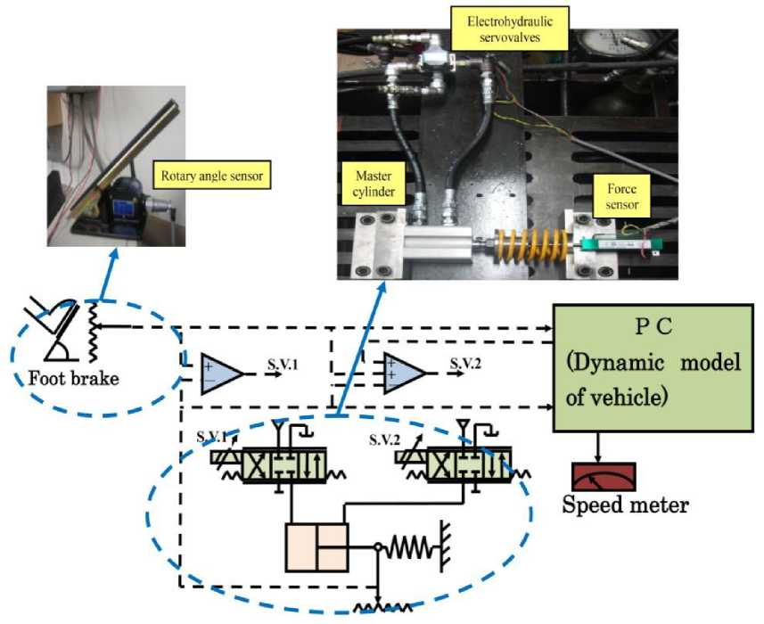
Fig. 1: Main parts of HIL simulation for the ABS
In Fig.2, F z is the normal force at the tire-road contact point; λ is the longitudinal slip; β t is the side-slip angle of the wheel; θr is a set of parameters which characterize the shape of µ Expression (2) can be further elaborated. The vertical load can be simply described as F z = mg , while the longitudinal slip is given by
X -[-^-\—г- (3)
In the rest of the paper it is assumed that the braking maneuver is performed along a straight line. Accordingly, the dependence of F x on β t will be omitted:
Px = mgg(A; 6r) = mgg (-^-; 9r^ (4)
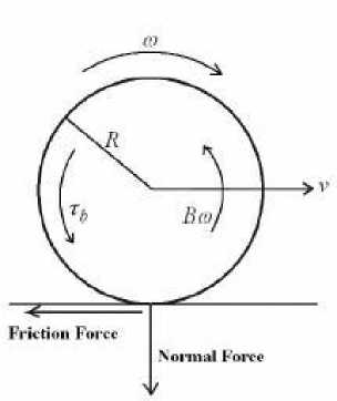
Fig. 2: Quarter-car model
Several tire friction models describing the nonlinear behavior are reported in the literature. There are static models as well as dynamic models. The magic formula which was derived heuristically from experimental data is the most simple and widely-used model for µ:
ц(Л, v) = [Сг(1 - ехр(—ЛС)) - ЛС3] ехр(—С4Лг) (5)
Л —
Г ГО) v
— (Н—— v, to = - (1 — Л)
V V г
into the first equation of (6a), so obtaining:
[Л = —
(Чт + ^тдци)*^» т V = — тдц)Х)
(6.b)
Table 1: Friction parameters
C1 maximum value of friction curve
C 2 friction curve shape
C 3 friction curve difference between the maximum value and the value at λ=1
C 4 wetness characteristic value and is in the range
0.02-0.04 s/m
By plugging (4) into (1), we finally obtain the following expression of the quarter-car model:
G to — г тд ц р-^) — Ть
1 fv-corX
т v = тдц (——)
(6.a)
As already remarked, in (6.a) the state variables are ω and v . Since ω, v and λ are linked by the algebraic relationship (3), it is possible to replace the state variable ω with λ. This can be obtained by plugging the following two relationships
Finally, there is the relationship between the pressure at the slave cylinder and the brake torque generated. Under steady state conditions a quasi-linear relationship can be assumed as follow:
Tfa — ЦИв-A w^B^w
Where ^ is mechanical efficiency, p B is brake lining coefficients of friction, A w is the effective wheelcylinder piston area, R B is mean effective radius of brake lining contact, and P w is brake pressure. However, that relationship changes with temperature, vehicle speed, friction material and several other parameters. Unfortunately many of these states are immeasurable in real time and therefore inadequate for control.
-
III. Results
As the model is used in the context of HIL system, it has to run in real-time on the target. The model is embedded as an S-function into a Simulink model by using Simulink interface block [13]. By this way, the new set of parameters can be passed into the model in the form of an array of double values.
The HIL system presented in this paper is a very cost-efficient system, which is based on a normal PC platform. The communication between the simulation PC and the ABS test bench is realized. The performance of the ABS HIL system signals such as; ABS input, the displacements of the spools, pressures of the master cylinder sides, and its displacement are recorded and illustrated in Fig. 3. While Fig.4 shows the response of ABS and its master cylinder to foot brake push.
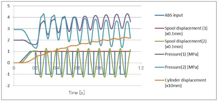
Fig. 3: The performance of the ABS HIL system
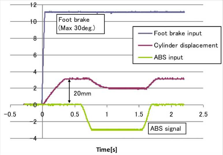
Fig. 4: the response of ABS and its master cylinder to foot brake push
-
IV. Conclusion
Real-time HIL simulation technology is increasingly becoming an important tool for the development of much higher quality vehicle electronic controllers of ever control system with greater complexity and sophistication. This hardware-in-the-loop simulator system of ABS can show how the electron devices work in a rapid and economical method. The Matlab language is used to modeling and simulation of the virtual vehicle dynamic model. As in the modeling and simulation process, these enable it to settle the problem of different domain coupling, such as control algorithm, electronics and mechanical, etc. The nice interface makes the system easier to use as teaching demo software. Finally, the experiments results indicate that modeling and HIL scheme for evaluating ABS is effective and feasible.
Acknowledgments
The author would like to acknowledge Prof. Hidetoshi Ohuchi, University of Yamanshi for his kind support and JASSO Organization, Japan for its financial support during this work.
References Hardware-in-the-loop of Simulation for a Hydraulic Antilock Brake System
- G.F. Mauer, “A Fuzzy Logic Controller for an ABS Braking System,”, IEEE Trans. On Fuzzy Systems, Vol. 3, No. 4, Nov. 1995.
- W.K. Lennon, K.M. Passino, “Intelligent control for brake systems,” IEEE Trans. Control Systems Technology, Vol. 7, pp. 188-202, March 1999.
- Lojko, B.-Fuchs, P."The Control of ASR System in a Car Based on the TMS320F243 DSP," Diploma Thesis, Dept. of Radio&Electronics, FEI SUT, Bratislava, 2002.
- A.G. Ulsoy, H. Peng, Vehicle Control Systems. Lecture Notes, ME 568, 1997.
- P.E. Wellstead, Analysis and redesign of an antilock brake system controller, IEEE Proc. Control Theroy Appl., Vol. 144, No. 5, September 1997, pp. 413-426.
- P. Hart, “ABS Braking Requirements,” Hartwood Consulting Pty Ltd , June 2003.
- Suh,M. W., Chung, J. J. and Kim, S. M. Hardware-in-the- loop simulation for ABS on PC. Int. J. Veh. Des., 24(2/3), 157–1702000,.
- Zhang Hongchang, Zhang Yunqing, and Chen Liping, “Hardware-in-the-Loop Simulation of Pneumatic Antilock Braking System Based on Modelica”, International Journal of CAD/CAM Vol. 10, No. 1, pp. 29~37, 2010.
- Chen, H. P., Chen, L. P., Wang, J. M. Model development and parameter investigation of a columntype electric power steering system. Int. J. Shanghai University (Engl Ed), 13, 6, 466-473, 2009.
- Hanselmann H, Hardware-in-the-loop simulations: Testing and its integration into a CACSD Toolset.
- IEEE International Symposium on Computer Aided Control System Design, Dearvorn, Michigan, USA, September; 15–18, 1996.
- Ayman A. Aly, “Intelligent fuzzy controller with road surfaces identifier for antilock brake system,” Int. J. Mechatronics and Automation (IJMA), Vol. 1, Nos. 3/4, pp 153-160, 2011, USA.
- Q. Ming, "Sliding Mode Controller Design for ABS System," MSc Thesis, Virginia Polytechnic Institute and State University, 1997.
- Mathworks. Simulink – Model-Based and System-Based Design, using Simulink.Version 4, 2001.
