Hybrid Communication System Based on OFDM

Author: Farman Ullah, Nadia N Qadri, Muhammad Asif Zakriyya, Aamir Khan
Journal: International Journal of Information Technology and Computer Science(IJITCS) @ijitcs
Article in issue: 12 Vol. 5, 2013.
Free access
A Hybrid architecture between terrestrial and satellite networks based on Orthogonal Frequency Division Multiplexing (OFDM) is employed here. In hybrid architecture, the users will be able to avail the services through the terrestrial networks as well as the satellite networks. The users located in urban areas will be served by the existing terrestrial mobile networks and similarly the one located in rural areas will be provided services through the satellite networks. The technique which is used to achieve this objective is called Pre-FFT adaptive beamforming also called time domain beamforming. When the data is received at the satellite end, the Pre-FFT adaptive beamforming extracts the desired user data from the interferer user by applying the complex weights to the received symbol. The weight for the next symbol is then updated by Least Mean Square (LMS) algorithm and then is applied to it. This process is carried out till all the desired user data is extracted.
Hybrid Communication, OFDM, CCI, Beamforming, Pre/Post FFT Beamforming
Short address: https://sciup.org/15012002
IDR: 15012002
Text of the scientific article Hybrid Communication System Based on OFDM
Published Online November 2013 in MECS DOI: 10.5815/ijitcs.2013.12.04
In today’s world the need for communication has driven the researchers towards higher data rates and all time connectivity. This step towards higher data rates has enforced a lot of pressure on communication networks. In order to meet this requirement, communication networks with sophisticated technology are needed. As a result, systems with advance antennas and signal processing are a promising solution. But only provisioning of higher data rates can neither create an effective network nor can it support large customer base. In order to provide global connectivity and supporting a rich customer base the communication network should not be bound to time or location. This approach towards provisioning of connectivity at every time and every place is a dominating aspect towards successful communication networks in the future.
In order to deal with this problem, a hybrid architecture based on OFDM system is modelled and is presented in Fig 1. It is shown that the users located in rural areas are served directly from the satellite spot
-
II. Methodology
-
2.1. System Model
This part presents the detailed procedure of the system model.
The hybrid system scenario and block diagram of OFDM system model is presented in fig 1 and fig 2 respectively with the beamforming at the satellite end. Starting from the data generation block or source, which generate random data, is followed by the Modulator. The Modulator modulates the data according to the type of modulation scheme used. Here we are using both BPSK and QPSK and will analyze their performance. After modulation the pilot insertion takes place. Pilots are known data to the receiver which is used to estimate the channel [4]. Pilots can either be inserted with specific period uniformly between the data sequence [5]. Here in our system five pilot have been inserted in to the data sequence. After pilot insertion with the mapped data the output in frequency domain of multiuser case is expressed as, taking one symbol at a time.
x ( i , j ) = ( x (1, j ), x (2, j ),....... x ( N , j )) T (1)
Where x shows the nth subcarrier of the jth user, where n = 1, 2, 3, ....,N and j = 1, 2, 3, . . . ,J and (.)T represents the transpose.
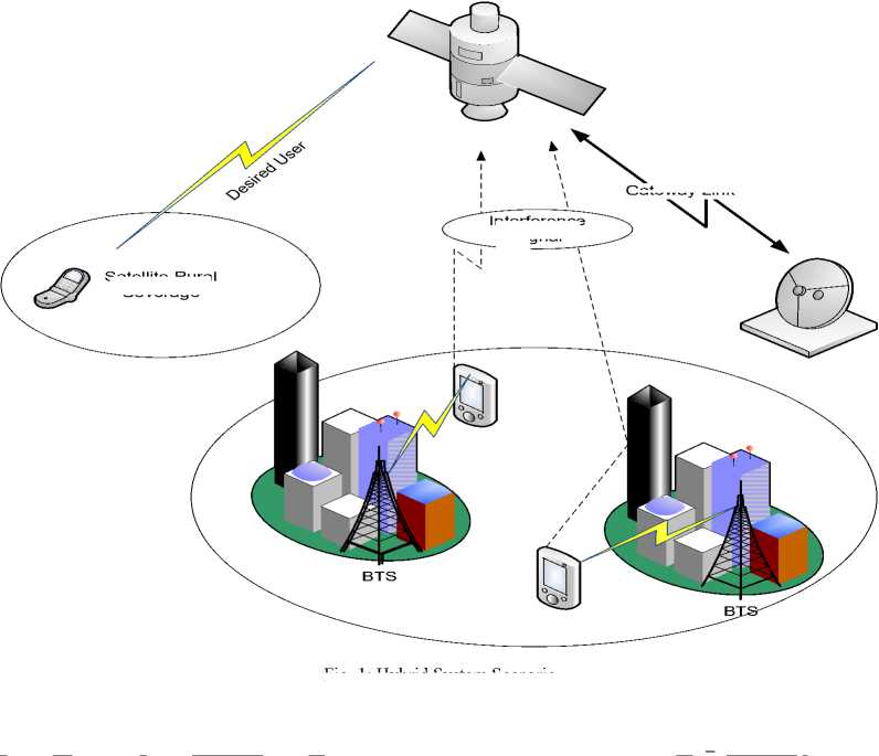
Fig. 1: Hybrid System Scenario
~
Satellite Rural Coverage
Gateway Link
Interference Signal

Fig. 2: OFDM System Model
Up to now the signal is in frequency domain. Right after the pilot insertion the signal is transformed into time domain by using IFFT.
X j = F H X j (2)
In (2), x(i,j) = x(1,j), x(2,j),......x(N,j) is the time domain symbol of an OFDM system and F shows the matrix for FFT operation and (.)H shows the Hermitian transpose. After the transformation of signal from time domain to frequency domain, then comes the block of cyclic prefix extension. Cyclic prefix cyclically shift the symbol, means that the last G elements of an OFDM symbols are copied and placed at the start. The purpose of cyclic extension is to overcome the effect of ISI (Inter Symbol Interference) [6][7]. Here cyclic prefix of 1/4th of the symbol length is used. The process of inserting guard interval can be represented using the following equation [8].
N , G
X j = J KF H (3)
N
In (3), x~. = [x(N-G +1 j■), x(N-G+2,j),.. .., x(N-1,j), x(N ,j), x(1,j), x(2,j), .... , x(N,j)]T is the OFDM symbol with the cyclic prefix. N,G in (3) is containing the last G rows of matrix IN, which is an identity matrix of size N. After this process the data is converted to serial form by passing it through parallel to serial converter (P/S), which is ready to be transmitted over the channel. Channel effect can be expressed as [8]
y j = X j Nh j k (4)
where k shows the index of time, so passing through the channel, the signal is received at the receiver from the desired source and other sources of interference. But here in this paper the channel effect is not included. When the signal is received at the satellite antenna element, after removing the cyclic prefix the signal matrix for one OFDM symbol can be represented as [9]
-
V = AYH + N (5)
-
2.2. Adaptive Beamforming:
In (5); A is the array response, Y is the received OFDM symbol and N is the noise. The key point to notice here is that the beamformer will take one OFDM symbol at time so the noise for that one symbol will be randomly generated. Referring to (2) and (5), a(s, j) is the element of A matrix which shows the array response of sth antenna elements and jth user. And a(s, j) is given by e'2ns ^dsn6 where the total number of antenna elements are s = 1, 2, 3, . . . ,S. Also the inter antenna element distance is given by d, and the direction of Arrival (DOA) for the jth user is given by 9, and the carrier wavelength is given by λ. In this paper we have modeled the linear array so the distance between inter-elements is da = k/2. In this way the array j2 ns лскпв response will be e A .
Likewise the received signal for jth user and nth subcarrier is given by y ( j, n ). This y ( j, n ) is the element of Y matrix. Also n ( s, n ) and v ( s, n ) are the elements of matrix N and V respectively representing the noise and output of beamformer for sth antenna element and nth OFDM subcarrier.
In order to mitigate the interference, beamformer processes the output of the antenna elements by applying complex weights to the symbols. This process is expressed as
-
r = wHV (6)
where r in (6) is termed as the weighted beamformer output and r = [ r ( 1 ) , r ( 2 ) , .... , r ( N )] and w is [ w ( 1 ) ,
w(2), .... , w(N)]T which is the complex weights. After the beamformer, serial to parallel (S/P) converter is applied to the received data. It is then converted into parallel sequence. After the data is transformed into parallel sequence, it is converted into frequency domain by applying FFT.
-
r = FrH (7)
-
r = r , Г 2,..... Гц is known as the OFDM symbol
received and it is in frequency domain. In order to update the weight for the next symbol what beamformer does is it takes the transmitted pilot sequence and also the pilots received an on the basis of these pilots it calculates the error vector [10]. Depending upon this error vector, adaptive algorithm based upon Mean Square Error (MSE) computes the next weight for the next symbol[10][11]. The error vector is shown below
-
ep = rpxp (8)
As it can be seen that the error vector obtained is in frequency domain while pre-FFT beamforming is done in time domain as said in the previous section. So there is a need to convert this error vector into time domain [12]. The transformation of error vector from frequency domain to time domain is expressed as below [13]
-
e p = F p He ~ P (9)
Here ep is the error in time domain Fp is the iFFT which transforms the error vector from frequency domain to time domain.
After the process of error calculation, Least Mean Square (LMS) algorithm is implemented in order to update the beamformers complex weights [8][14].
-
w l + 1 = w l + 2 M i e (10)
-
2.3. System Parameters and Performance
Here in this section the system parameters regarding transceiver are outlined. Regarding to the transceiver a SIMO OFDM system is used [18]. This transceiver transmits with one antenna and on the satellite end 2, 4 receive antennas are used. All the modulation schemes mentioned in table 1 are used for single and multi-user implementation of OFDM system. But in OFDM based adaptive beamformer, the source data is modulated using BPSK, QPSK and 8-PSK. 32 sub-carriers are used for one OFDM symbol and sub-carriers 1, 9,17,25,32 are allocated to pilot transmission [19]. The desired user is at 40 degrees with respect to satellite and three interference users are at -60, -30 and 70 degrees. The power of interference users is -5 dBW and -10 dBW. The value of μ which is the LMS step size is 0.0001.
In (10) l = 1, 2, 3, .... , L and it corresponds to the lth symbol of OFDM. Using the weight equation, new weights for the next symbol is calculated. v(l) is the output of the beamformer and ep(l) is error vector and μ is the adaptive step size for the LMS algorithm [15][16][17]. We repeat the process till all the weights for all the symbols are calculated and the desired data is extracted.
As OFDM now a days is widely being used in 3GPP standards. So this system has been implemented on a 3GPP standard as well. According to the standard 256 sub-carriers are used and pilot transmissions occur after every 6th subcarrier [20].
Table 1: System Parameters
|
Parameter |
Value |
|
Modulation Scheme |
BPSK,QPSK,8-PSK,16\QAM |
|
Number of subcarriers |
32 |
|
Number of symbols |
20,000 |
|
Pilot Location |
{1, 9, 17, 25, 32} |
|
Cyclic Prefix |
8(1/4) |
|
Antenna Elements |
2, 4 |
|
Number of users |
4 |
|
Desired User Power |
0 dB |
|
Interferer User Power |
-5, 10 dB |
|
LMS adaptive step size (μ) |
0.0001 |
-
III. Results and Discussions
This section gives the simulation results generated from implementation of single and multiuser OFDM system
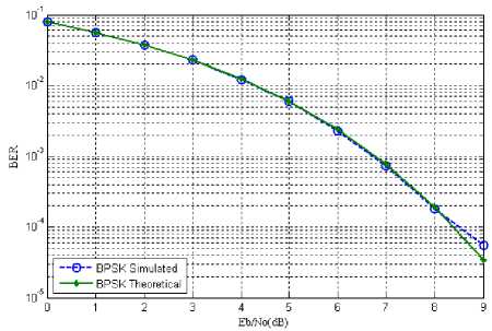
Fig. 3: BER vs Eb/No for BPSK
Fig 3 shows the performance of the system in terms of BER and Eb/No. Simulated curve is plotted against the theoretical curve which proves that the OFDM system is working properly.
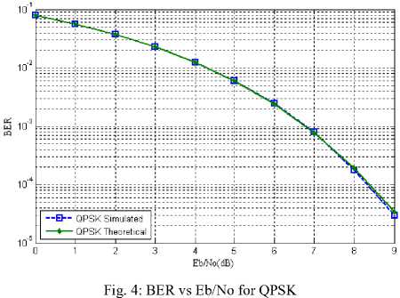
BER is plotted against QPSK for QPSK. There is not much different between BPSK and QPSK performance because the two more bits can be sent in the constellation of BPSK without putting more energy as they still will be orthogonal to each other.
Fig. 5: BER vs Eb/No for 8-PSK
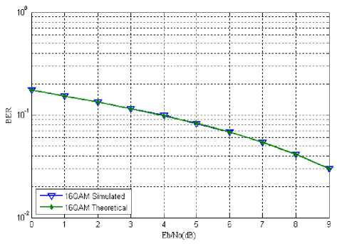
Fig. 6: BER vs Eb/No for 16QAM
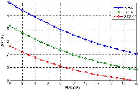
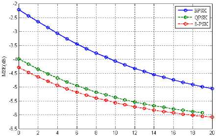
Fig. 8: Desired user Eb/No vs MSE for s=2 and M-PSK={2, 4, 8}
Two scenarios are used in beamforming environment. In the first scenario the interferer power is taken as -10dBW and comparison of different modulation schemes in combination with antenna elements is made. Whereas in second scenario the power for interference users is set to -5dBW.
-
3.1. Scenario 1: Interference level -10dB
In first scenario we have used the interferer users with power of -10dBW. Fig 7 below shows the results of first scenario comparing the system performance in terms of Bit Error Rate (BER).
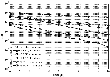
Fig. 7: System performance vs desired user Eb/No for s={2, 4}, M-PSK {M=2, 4, 8}
We have observed that there is degradation in system performance with the use of higher order modulation. This is because, higher order modulation schemes carry more data and are not as robust as lower order modulation schemes. It is also observed that BPSK and QPSK perform better as compared to 8-PSK. Fig 7 also depicts that system gives much better performance when antenna elements are increased from 2 to 4.
Fig 8 depicts the system performance based on MSE. It is seen from the graph that increase in E b /N o results in decrease of MSE. One thing to note here is this that higher modulation schemes have lower MSE as compared to lower order modulation scheme. Once the convergence is achieved adaptive beamformer lowers the MSE values [21].
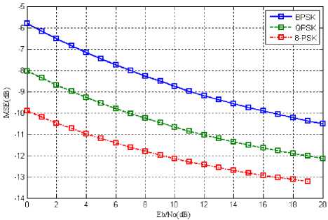
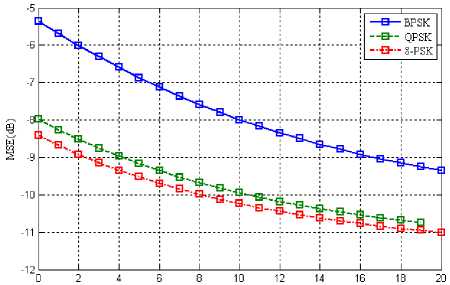
Fig. 9: Desired user Eb/No vs MSE for s=4 and M-PSK={2, 4, 8}
Fig 9 shows the comparison between Eb/No and MSE with the use of 4 antenna elements. Comparing the results depicted with those shown in fig 8, we can analyze that with the use of 4 antenna elements we have lowered the MSW by almost 3dB. Therefore increasing the antenna elements result in decreasing the MSE.
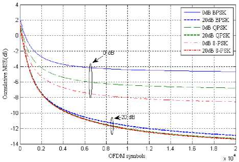
Fig. 10: Cumulative MSE vs time (OFDM symbols) for s=2, M-PSK= {2, 4, 8}
Fig 10 shows the cumulative MSE against OFDM symbols at desired value of Eb/No. 20,000 symbols were transmitted and at each symbol the error value is calculated at desired value of Eb/No and plotted as above. It is observed that as the symbols are received the error values along with the receiving symbols keep on decreasing. As the beamformer converge, the error gets to minimum.
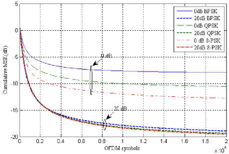
Fig. 11: Cumulative MSE vs time (OFDM symbols) for s=4, M-PSK= {2, 4, 8} to -10dB, it is quite clear that the system has degraded in performance with increase in the interference.
Eb/No(dB)
Fig. 13: Desired user Eb/No vs MSE for s=2 and M-PSK={2, 4, 8}
Fig 13 shows the performance in terms of Eb/No and MSE. This plot is taken at interference level of -5dB, comparing it with fig 8 where the plot was at interference level of -10 dB clearly shows that first scenario with interference -10dB out performs the second one.
Fig 11 shows the same result but using 4 antennas instead. It is quite clear that using large antenna elements result in less error. Keeping the rest of the parameter same and changing the antenna elements from 2 to 4, resulted in decrease in cumulative MSE. The margin is quite clear from fig 10 and fig 11 values are plotted against 20dB Eb/No.
-
3.2. Scenario 2: Interference level -5dB
In the second scenario we set the power of the interference users at -5dB and study how this change effects on the system performance.
EbW®
Fig. 14: Desired user Eb/No vs MSE for s=4 and M-PSK={2, 4, 8}
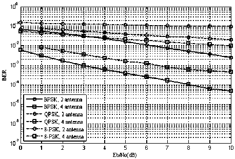
Fig. 12: System performance vs Eb/No for s={2,4}, M={2,4,8}, Interference power = -5dB
Fig 12 represents the system performance in terms of BER and Eb/No using different antennas and different modulation schemes but the for interference user power is set to -5dB. Comparing fig 12 with the first scenario results shown in fig 7 where interference power was set
Comparing with the results shown in -10dB scenario, the results plotted in fig 14 are better than the result produced in fig 9. This is because the antenna elements have increased. But change in interference power has showed its effect as well. The performance has been degraded when compared with fig 9.
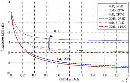
Fig. 15: Cumulative MSE vs time (OFDM symbols) for s=2, M-PSK= {2, 4, 8}
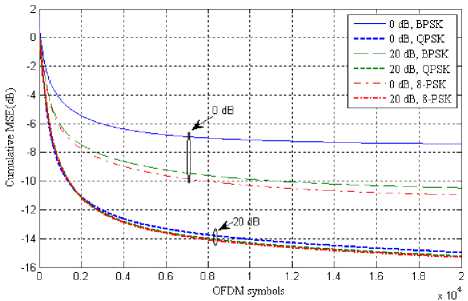
Fig. 16: Cumulative MSE vs time (OFDM symbols) for s=4, M-PSK= {2, 4, 8}
Fig 15 and fig 16 shows the result for 2 and 4 antenna elements at interference level of -5dB. Out of both the latter performs better as antenna elements are increased.
-
IV. Summary
In this paper, a hybrid architecture based on OFDM is employed where both the terrestrial and satellite networks can co-exist with each other. Users are able to use either terrestrial link or satellite link depending upon their location in a transparent manner. So in hybrid architecture there is a reuse of frequency. This frequency reuse induces CCI. The modeled employed is to overcome this uplink CCI. In order to mitigate this uplink CCI caused by frequency reuse adaptive beamforming is employed. An OFDM based adaptive beamforming in implemented in this paper so as to alleviate this interference. Terrestrial users operate OFDM because of its high data rate and its robustness and at the satellite end Pre-FFT beamforming also known as time domain beamforming is implemented.
Different scenarios have been modelled in order to evaluate the performance of the system. The simulations were carried out for different modulation schemes so as to conduct comprehensive analysis. Different parameters were used to have a fair comparison and also the system performance is tested for different interference levels.
References Hybrid Communication System Based on OFDM
- Ammar H. Khan, Muhammad A. Imran and Barry G. Evans, “OFDM based Adaptive Beamforming for Hybrid Terrestrial-Satellite Mobile System with Pilot Reallocation,” International workshop on satellite and space communications IEEE, pp 201-205.
- Litwin, L. and Pugel, M, “The Principles of OFDM,” RF signal processing Magazine Jan 2001 pp 30-48, www.rfdesign.com Accessed [ 21 April 2010].
- Shaoping Chen and Cuitao Zhu, “ICI and ISI Analysis and Mitigation for OFDM Systems with Insufficient Cyclic Prefix in Time-Varying Channels,” IEEE Transaction on Consumer Elecronics, vol. 50, No. 1, Feb 2004.
- C. K. Kim, K. Lee and Y.S. Cho, “Adaptive beamforming algorithm for OFDM systems with antenna arrays,” vol. 46, no. 4, pp. 1052-1058, Nov. 2000.
- H. Matsuoka and H. Shoki, “Comparison of pre-FFT and Post-FFT processing adaptive arrays for OFDM system in the presence of co-channel interference,” in Proc. 14th IEEE on Personal, Indoor and Mobile Radio Communications PIMRC 2003, vol.2, 7-10 Sept. 2003, pp. 1603-1607.
- D. Zheng and P. D. Karabinis, “Adaptive beamforming with interference suppression in MSS with ATC,” [Online]. Available: www.msvlp.com
- William Y. Zou and Yiyan Wu, “COFDM: An Overview,” IEEE Transactions on Broadcasting, vol. 41, NO, 1, March 1995.
- P.D. Karabinis, “Systems and methods for terrestrial reuse of cellular frequency spectrum,” USA patent 6 684 057, January 27, 2004.
- P.D. Karabinis, S. Dutta, and W. W. Chapman, “Interference potential to MSS due to terrestrial reuse of satellite band frequencies,” [online]. Available: www.msvlp.com
- W. G. Jeon, K H. Chuang, and Y. S. Cho, “An equalization technique for orthogonal frequency division multiplexing systems in time-variant multipath channels,” IEEE Trans. Commun., vol. 49, pp. 1185–1191, January 1999.
- (S. Colieri, M. Ergen, A. Piro, Bahai. A study of channel estimation in OFDM systems Vehicular Technology Conference, 2002. Proceedings VTC 2002-Fall. 2002 IEEE 56th, Vol. 2 (10 December 2002), pp. 894-898 Vol. 2.
- L. Hanzo, W. Webb, and T. Keller, “ Single and Multi-carrier Quadrature Amplitude Modulation: Principles and Applications for Personal Communications, WLANs and Broadcasting,”. John Wiley and IEEE Press 2000.
- F.Mueller –Roemer, “Directions in audio broadcasting,” Journal of the Audio Engineering Society, vol.44, pp.158-173, March 1993 and ETSI, Digital Audio Broadcasting (DAB),2nd ed.,May 1997. ETSI 300 401.
- ETSI,Digital Video Broadcast (DVB);Framing structure, channel coding and modulation for digital terrestrial television, August 1997. EN 300 744 V1.1.2.
- H.Sari, G. Karam, and I. Jeanclaude, “Transmission techniques for digital terrestrial TV broadcasting,”IEEE Communications Magazine, pp.100-109, February 1995.
- ANSI,ANSI/T1E1.4.94-007, Asymmetric Digital Subscriber Line (ADSL) Metallic Interface., August 1997.
- R. Prasad and H. Harada, “A novel OFDM based wireless ATM system for future broadband multimedia communications,” in Proceeding of ACTS Mobile Communication Summit ’97,(Denmark), pp. 757-762, ACTS, &-10 October 1997.
- Barry D. Van Veen and Kevin M. Buckley, “Beamforming A versatile approach to spatial filtering,” IEEE Signal Processing Magazine vol. 5 No. 2 April 1988 pp4-24.
- Cox, H. [1973], “Resolving power and sensitivity to mismatch of optimum array processors,” Jour. Acoust. Soc. Amer., Vol. 54 No. 3, pp. 771-785, 1973.
- Jim Zyren, “Overview of the 3GPP Long Term Evolution Physical Layer,” Document Number 3GPPEVOLUTIONWP Rev0, 07/2007.
- Ming LEI, Ping ZHANG, Hirshi HARADA, Hiromitsu WAKANA, “LMS Adaptive Beamforming based on Pre-FFT combining for Ultra High Data-Rate OFDM system,” Proc. IEEE 2004.
