Hybrid Method for the Navigation of Mobile Robot Using Fuzzy Logic and Spiking Neural Networks

Author: Zineb LAOUICI, Mohammed Amine MAMI, Mohamed Fayçal KHELFI
Journal: International Journal of Intelligent Systems and Applications(IJISA) @ijisa
Article in issue: 12 vol.6, 2014.
Free access
The aim of this paper is to present a strategy describing a hybrid approach for the navigation of a mobile robot in a partially known environment. The main idea is to combine between fuzzy logic approach suitable for the navigation in an unknown environment and spiking neural networks approach for solving the problem of navigation in a known environment. In the literature, many approaches exist for the navigation purpose, for solving separately the problem in both situations. Our idea is based on the fact that we consider a mixed environment, and try to exploit the known environment parts for improving the path and time of navigation between the starting point and the target. The Simulation results, which are shown on two simulated scenarios, indicate that the hybridization improves the performance of robot navigation with regard to path length and the time of navigation.
Mobile Robot, Navigation, Fuzzy Logic, Spiking Neural Networks, Unknown Environment
Short address: https://sciup.org/15010631
IDR: 15010631
Text of the scientific article Hybrid Method for the Navigation of Mobile Robot Using Fuzzy Logic and Spiking Neural Networks
Published Online November 2014 in MECS
Navigation is one of the most challenges in the mobile robot theory. It has several problems to be solved: how to avoid obstacles, how to find and construct a collision-free path from a starting point to the target in known, partially known or totally unknown environments. These challenges are related to the use of mobile robot, as the requirements and the uses of mobile robot extend, as the robot’s navigation will be face to more challenges.
In order to solve these problems and have an autonomous mobile robot, which will be able to navigate and react in the environment properly, several methods are developed in literature [1-2-3-6-7-9-10]. Each developed method is used to solve the problem of navigation. Our aim in this study is to build a method, which improves the robot’s navigation in partially known environment. To choose between the classical methods and the new methods we have done a comparison between the Fuzzy Logic (FL) method and Bug2 method [3-4]. This comparison shows the utility of FL approach.
The fuzzy logic technique is used in many works to deal the navigation task. In [6] the author use fuzzy logic to build elementary controllers, but his study focused also on how to coordinate the elementary behaviors, a comparison is done between two proposed methods to select the best. The author of the both papers [7-8] proposed an approach for the fuzzy logic based control by multi-sensor integration. According to this approach, the fuzzy reasoning performs the coordination for the avoiding obstacles, following edges and moving towards target behaviors. In addition, in [14] the author focused on developing a fuzzy rule based system, his strategy has the capability to build and update a topological map. The Fuzzy logic method has the same reaction even there are known areas, as results the FL method cannot benefit from these known areas to ameliorate the robot’s navigation.
This study [15] proposed a new local navigation technique uses the avoidance obstacle technique. The author in [12] propose new mathematical approach generate a 3D path; the robot can reach and truck moving targets.
Our idea of navigation in known area is mainly inspired from the approach reported in [1], which upon on the spiking neural networks (SNN), the simulations of this method show that the robot finds the optimal path. To achieve our purpose, we develop an algorithm Fig.10 that combines the latter and the FL method. It ensures the use of methods according to the circumstances in order to construct an optimal path from the starting to the final configuration. The influence of our hybridization on the navigation of the mobile robot is proved using a set of simulations between our hybrid method and the fuzzy logic method. The simulation results include the paths of the robot's navigation and a set of curves representing the comparisons of the required parameters: distance and time of navigation. The simulations are carried out using the Python programming language.
This paper is organized as follows: The next section discusses the navigation in unknown environment using Fuzzy Logic technique. The navigation in known environment is discussed in section 3. In section 4 we describe the hybridization procedure and the evaluation of our method using simulation. Section 5 concludes our work with a summary.
-
II. Navigation using Fuzzy Logic (FL)
The proposed method of navigation in unknown environment is based on the fuzzy logic technique. It has composed of two behaviors (controllers): the first controller is used when there is no obstacle face to the robot; the second controller is launched when an obstacle is detected.
We bring the behaviors from existing methods and we make some changes to be suitable with our case. We solve the case of corners. The first controller is brought from [10]. The second controller is brought from [11]; in this controller, we change the membership functions of the input and output variables after many tests and simulations. We also give a static value to the velocity output variable for the both controllers. The steps followed by the robot are presented in Fig.1:
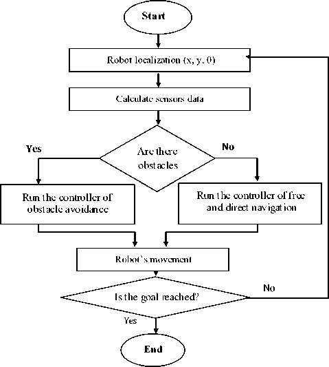
Fig. 1. The sequencing of navigation steps using FL
As mentioned previously, our fuzzy system is composed of two behaviors. Each one, works independently of the other, thus we need a mechanism that coordinate the both behaviors in order to have a good reaction with the environment. Several methods are proposed in literature to solve this problem: behavior arbitration [6-9], weighted [7-8] and the switching between behaviors method. For our system, we use the switching between behaviors, our choice is based on a comparison done between our system and another method [6] use the behaviors' arbitration method (two methods are proposed in this work [6], we choose the best of them for the comparison), we built the same environment. As shown in the simulation results, our method gives approximately the same results Fig. 2.
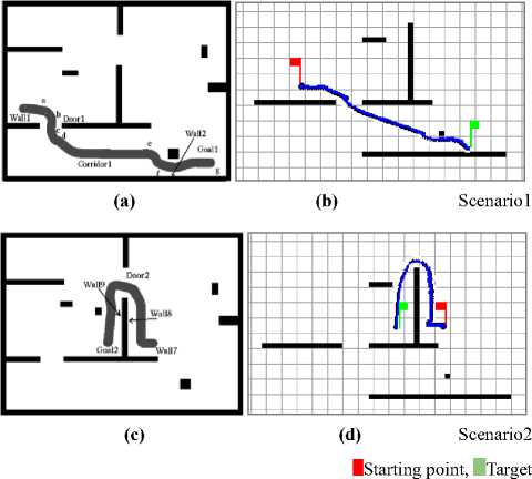
Fig. 2. Simulation results of Fuzzy Logic navigation method (b,d) Vs [6](a,c)
-
A. The implementation of the navigation controllers (behaviors)
The first behavior is executed when no obstacle is detected by the robot. When the robot finds an obstacle, it uses the second fuzzy controller to avoid the obstacle.
To implement these two fuzzy controllers, we need to specify input, output variables, the membership functions of these variables and the inference system which represented by rules base.
-
B. Input and output variables
The input variables of the free navigation controller are the distance and the angle between the robot and the goal. The output variable is the steering angle. Avoidance obstacle controller uses two input variables, which are the distance between the robot and the obstacle, as well as the angle between the current robot direction and the obstacle. The output variable of this controller is the steering angle.
According to received range information, reactive controllers of the fuzzy logic algorithm are used to control the steering angle. Initially we give a static value to the velocity.
-
C. Fuzzification and membership functions
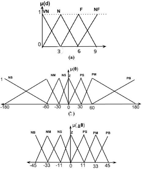
According to [10], the linguistic variables Z(zero), VN(Very Near), N(Near), F(Far), VF(Very Far) are used to fuzzify the input variable distance and NB(negative big), NM(N medium), NS(N small), Z(zero), PB(positive big), PM(P medium), PS(P small) are used to fuzzify the angle between the robot and the target as well as the output variable steering angle.
The second controller, which is the obstacle avoidance behavior (OAB), uses the following fuzzy set: VN (very near), N (near), F (far), VF (very far) to fuzzify the distance input variable, which represents the distance between the robot and the obstacle. As will as the angle between the robot and the obstacle which is represented by this fuzzy set: NB (negative big), NM (N medium), NS (N small), Z (zero), PB (positive big), PM (P medium), PS (P small).
The obstacle avoidance behavior produces an output variable which is the angle that the robot must turn with it (steering angle) in order to get the appropriate direction. The membership functions used to represent the input and output variable are represented in Fig.3.
(b)
(c)
Fig. 3. The membership functions of input (a,b)/output(c) variables for obstacle avoidance behavior (OAB)
Fuzzy controllers are described using fuzzy set and inference system (fuzzy logic rules), fuzzy rules are integrated in two independents rule bases to explain how both controllers, free navigation and avoidance obstacles, are realized. We use the Mamdani (max-min) inference method for the both controllers and the centroid of area (COG) defuzzification method to defuzzify the output variables.
One of the navigation problems is how the robot reacts when there are corners Fig.4. In our solution when a corner is detected, the robot creates a virtual goal behind the wall encountered it, and when the robot passes the wall, it returns to the main target (this process is described in Fig.4).
In Fig.4 (a) the robot starts from (SP) to (Tp), when the robot detects that there is a corner at p1 point, it creates a virtual goal (vg) behind the wall1, and thus the robot navigates to reach it. At (p2) it passes the wall and returns to the origin target. The robot forward to reach the target till (p3) it detects a new wall, the robot do the same reaction to avoid the second and the third wall then it is reached the target.
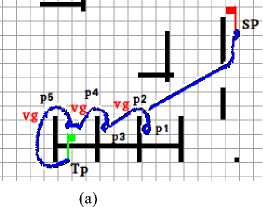
Fig. 4. Simulation show the solution of how the robot reacts when there is corners
-
D. Comparison with bug2 algorithm
Bug2 is one of the Bug’s family, which represent a set of navigation algorithms those utilize the BoundaryFollowing and Motion-to-goal techniques to generate the path in unknown environment. If the robot uses these algorithms face to an unknown object, it can find a collision-free path by contouring this object.
-
1) The principle of bug2 algorithm
The main idea of bug2 algorithm is that the mobile robot moves toward the goal by following a constant slope computed initially between these two positions S(start point) and T(target point), unless encounters an obstacle. The robot goes around the obstacle until arrives to the initial slope again. [3]
-
2) Simulation results of Fuzzy Logic and Bug2
Bug2 Fuzzy logic
Scenario1
Scenario 2
Scenario 3
Fig. 5. Simulation results of FL Vs BUG2 navigation methods
-
3) Discussion
As shown above in the simulation results between the FL and Bug2 navigation methods, FL is better than Bug2, it finds an optimal path between the starting and target point. Consequently, FL has the less time of navigation.
-
III. Navigation using Spiking Neural Networks (SNN)
In order to find an optimal path to the goal in a known environment we have improved a part of this method [1], it’s based on the spiking neuron network. The general idea of the navigation is:
In the workspace, we have the starting point S and the target T. The target point T sends a wave that traverses the workspace, without moving through the obstacles. Each neuron receives this wave saves the first sender as it father and sends it to the directs neighbors through the workspace, the first point that sends the wave to the starting point S represents the father F of S, thus the robot moves toward the father F of each point, till reaches the target point T.
-
A. How the wave spreads in the environments
At the first time the target point sends a wave to it direct neighbors Fig.6 (b), each neighbor sends this wave to it direct neighbors Fig. 6(c). The neuron that receives this wave and has not activated in the previous step will be active in this current step. The wave will spread in the environment using this mechanism till reaches the starting point.
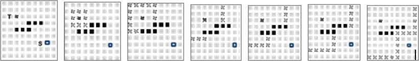
(a) (b) (c) (d) (e) (f) (g)
Fig. 6. The spread of the wave into a known environment
-
B. Neural Network Architecture
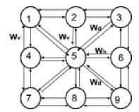
The workspace is discrete; it’s represented as a grid suchas a cell contains a robot. Every cell in the grid is represented by a neuron. Each neuron is connected with its eight direct neighbors (horizontal, vertical and diagonal); except the neurons situated at the corners and sides, Fig.7 (b) represent how a neuron (n 5 ) is connected with neighbors. The arrangement of neurons coincides with the discrete structure of the workspace. Each neuron communicates and runs its own computations only with its direct neighbors.
Neurons those represent the obstacles in the workspace haven’t any connection with their direct neurons neighbors. We use the spiking neuron in order to implement the neural network.
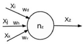
A neuron is composed of Fig.7 (a):
Multi connections: allow each neuron connecting with their direct neighbors.
A connection between two neurons i and j has a weight W ij , which has a static value. The horizontal (W h ) and vertical (W v ) links or connections have the same value (val 1 ), and have a different value (val 2 ) for the diagonal (W d ) connections, where val 2 > val 1 .
A function g add the weight W ij to the value S i of the sender neuron , the current neuron save the result of this function as Si :
g i = S + W ij , S i ^ g i
(This means that S i get thevalue of the function g i )
-
j: represents the sender neuron
S i :represents the value of the function g for the sender neuron j
W ij : represents the weight between the current neuron i and the sender neuron j , this value differ according to the kind of link (horizontal, vertical or diagonal).
The workspace (W) is represented by a set of neurons; each one is defined by a couple:
W= {n 1 , n 2 … n k }, n 1 : neuron 1 , k : the number of all neurons in the workspace. ni=(IDi, sti, NGi), where:
IDi: Identifier of the neuron i , sti: represents the state of neuron i (Active or not active), this state is related to the own state of i and also the state of their neighbors.
NG i = {(id 1 , w i1 ), (id 2 , w i2 ) … (id j , w ij )}
NG : represents the neighbors of neuron i :
id j : Identifier of the neuron neighbor j , j is the maximal value of a neighbor neuron of i .
Wi j : represents the weight of link that is wired the neuron i and their neighbor j .
(b)
Fig. 7. Neural model (a), Connections of a neuron with the neighbors (b)
(a)
-
C. Path Planning Process
At the first time, not all neurons in the workspace (W) are active; the neuron corresponds to the target initializes and sends the wave in order to reach the starting neuron. The main functions of our method are presented in the following pseudo code, its represents how the wave is spreading in the workspace (W) and how the robot finds an optimal path to the goal:
-
1. Proc initlz_network (): this function initializes the neurons network, the state of neurons and the weight of the connections between them.
-
2. Proc trgt_neur_initialz_wave: This function is private to the target neuron, which starts spreading wave.
-
3. To spread the wave in all network, each neuron receives the wave, executes the function Proc neuron_receive_wave .
-
4. When the wave arrives to the starting neuron, this
neuron run the function.
"Proc neurstart receive wave"
_ _
^^^^^^
D. Pseudo-code of the main functions
|
Proc initiz_network(): |
||
|
For ail neurons: State,=passive S=-l For i in all neuron : |
||
|
If! andj are not obstacles then: If connect: is vertical or horizontal: Wipvall Else(connectjjis diagonal): Wi;=val2 End |
||
|
End End |
||
|
End note: val2>vall |
||
|
i |
Drocnt |
iliron receive wave(Sj): |
|
If nt else |
^urp's the start_neuron then: neur_start_.recv_ wa ve(S) if n euri not activated at (t-1): |
|
|
g=Sj+Wij
if g Si=g State,=active Father,=j Resend_ wave_to_neighbors(Sj) State:=passive End |
||
|
Ent |
End 1 |
|
|
i |
^nd |
|
|
i |
"’roc trgt_neurjnitialz_wave(i) State! =active Fathen=i Si=O Send_ wave_ to_neighbors(SJ State/=passive 'nd |
|
|
i |
^rocnt Fa. Wi 1 'nd |
=ur_start_receive_ wave(Sj): theri=j He not reach_the_start_neur: Mo ve_ to ward_father,() 'nd |
Fig. 8. Pseudo code of the main functions
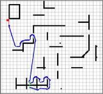
E. Scenarios of robot's navigation using our method
IStarting point, Target.
Fig. 9. Scenarios of robot navigation using our method
-
VI. Hybridization Procedure
-
2. An optimal path between the starting and target point.
-
3. Improvement of the time of navigation.
The FL is used when the environment is unknown, it has also the same reaction when the environment is known, because it is based on the avoidance of obstacles encountered by the robot, thus it can’t benefit of having known part in the environment.
Our contribution represents a hybrid method, it combines two navigation methods: fuzzy logic (FL) and the method based on spiking neuron network (SNN), and lock to get the advantages of each one in order to ameliorate the global navigation when the environment is partially known. Our method has the following properties: 1. Less calculations in the processing algorithm
A simulation done proves all this advantages. The results are represented in the next section.
-
A. How to build our hybrid method
The robot has two behaviors FL and SNN, the robot runs the behavior adequately with it localization, if it’s situated in an unknown area of the environment it calls the FL method, else the robot runs the SNN method.
When the robot runs the FL method, it will re-execute the previous steps after each movement until reach the target. If the robot is located in a known environment, it runs the SNN method, there are two cases: the robot executes SNN method directly and finishes the navigation, when the robot runs the FL method; it will re-execute the previous steps after each movement until reach the target. If the robot locate in a known environment, it runs the SNN method, there is two sub cases: executes SNN method directly and finish the navigation, when the target is situated in this known part, the second sub case is when the target is out of this area, thus the robot creates a virtual target (VT) on the limits of this known area then apply the SNN method, the VT is the nearest point to the original target. When the robot reaches the virtual target it re-executes the previous steps until reaches the original target. The main algorithm is presented in Fig.10:
-
B. Simulation & discussion
To show the influence of the combination done between the FL and the method of SNN on the global navigation of the robot, we have built complex workspace which contains different cases those the robot may encounter, as well as the realization of several simulations.
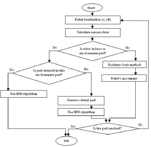
Fig. 10. The main algorithm that our hybrid method is based on.
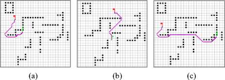
The environment is partially known, thus the robot has a plan about some areas, which are represented in both figures Fig.11 and Fig.14 by discrete lines, and the unknown parts are represented by continuous lines. The path of navigation using our method is blue when the robot uses the FL and pink when it uses the method based on the SNN, this path highlights the robot’s reactions with the state of environment (known, unknown) using each method.
(b)
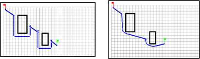
Starting point, Target
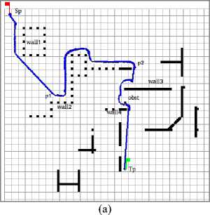
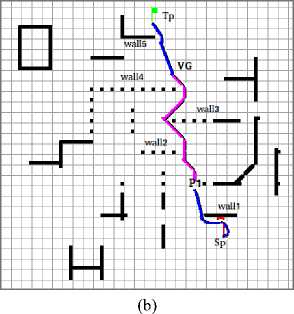
Fig. 11. The paths of the robot navigation using FL (a), our hybrid method (b) (scenario 1)
1) Scenario 1
(a)
(b)
(c)
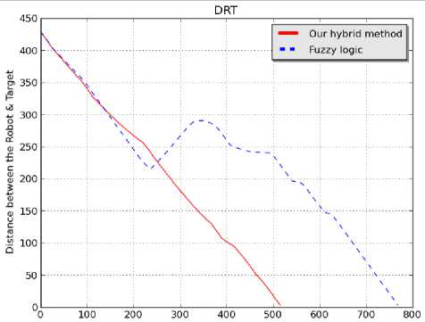
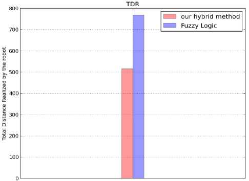
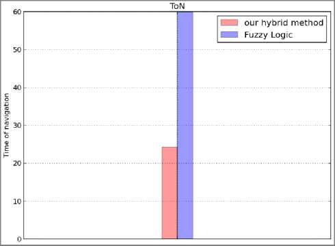
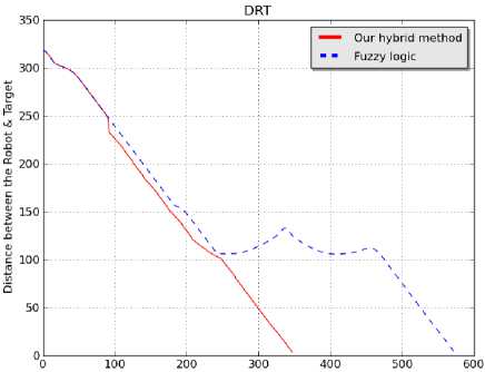
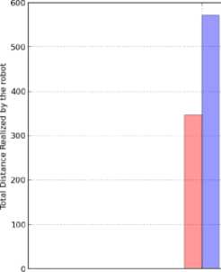
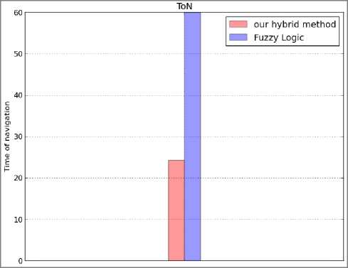
Fig. 12. Comparison between our hybrid method and Fuzzy logic of
DRT (a), TDR (b) and ToN (c) parameters (scenario 1)
In this scenario, the robot moves from a known to unknown part in the environment. A detailed description of the both simulation is given as follow:
-
1. Fig. 11(a) shows the simulation of the FL method, the robot moves towards the goal till encountered an obstacle (wall 1 ); the robot uses the avoiding obstacle behavior to move beside it. Then no obstacle is detected, the robot moves on a straight line towards the goal. At this point (p1), the robot is front of an obstacle, the robot moves beside it till reaches this configuration ( p2 ), at this point no obstacle is detected, thus the robot moves using the free navigation behavior till encounter the obstacle signed by (wall 3 ), followed by (obst) and (wall 4 ). Finally, the robot moves on a straight path till reaches the target (Tp).
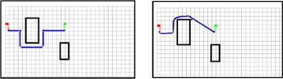
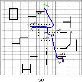
Starting point, Target.
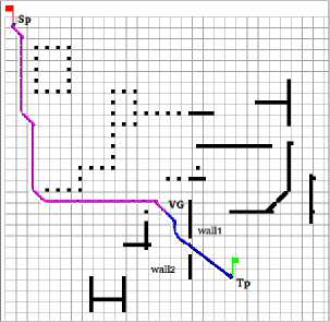
Fig. 13. The paths of the robot navigation using FL (a), our hybrid method (b)(scenario 2)
-
2. Fig.11(b) shows the simulation of our hybrid method, the starting point of the robot is in the known part, thus the robot use the method based on SNN to move (the path has a pink color). In the first step, the robot creates a virtual goal ( VG ) because the original goal isn’t located in this known part, then the path to the virtual goal is built, and the robot follows it till reaches the virtual goal (the path is created from SP to VG). In the second step, when the robot gets the virtual goal, it moves in the unknown environment, thus it switches to fuzzy logic method automatically (the path has a blue color), in this time the robot is face to a wall (wall1), the robot uses the avoiding obstacle behavior of the FL method to move beside it, till find a way to the goal and avoid the last obstacle (Wall 2 ) then the robot reaches the Target (Tp).
(a)
-
2) Scenario 2
In the second scenario the starting and target points are located in two different unknown environment parts, and between them there is a known part. The description of the both simulations results is given as follows:
-
1. Fig.13 (a) shows the simulation of the FL method, the robot avoids the obstacle encountered (wall 1 ), and moves beside it using the avoiding obstacle behavior. In addition, because no obstacle is detected, the robot moves on a straight line towards the goal. At this point (p1), the robot is front of an obstacle, it moves beside this obstacle on the left side till end. On (p2) the robot moves using the free navigation behavior till encountered another obstacle (wall4), the robot follows it, and when it’s front the corner (Cr) it rotates and moves till reaches the point (p3). At the final step, the robot moves on a straight line, it reaches the target (Tp) after avoiding the (wall 5 ).
-
2. Fig.13 (b) shows the simulation of our hybrid method, the starting point of the robot is in the unknown part, the robot move using FL method. At the first time it’s avoid the obstacle (wall1) then move directly towards the goal. The robot moves in the known environment part at (P1), it switches to (SNN) the path represented by pink color, creates a virtual goal at (VG) and follows this path till reaches this virtual goal (VG). The robot moves in the unknown environment after reaching the virtual goal(VG), thus it switches to fuzzy logic navigation method (blue path), the robot moves on a straight line till encountered an obstacle (the corner of wall5) near the goal, the robot reaches the target after avoiding (wall5).
(b)
(c)
Fig. 14. Comparison between our hybrid method and Fuzzy logic for
DRT (a), TDR (b) and ToN (c) parameters (scenario 2)
As shown in the above results Fig.11 and Fig.13, our method generates an optimal path better than the fuzzy logic method, as well as the diagrams of the both methods. When the robot uses our method, in order to reach the target, it's realized less distance Fig.12 (b), Fig.14 (b) and also less time of navigation Fig.12(c), Fig.14(c) compared to the fuzzy logic method. The Fig.12 (a), Fig.14(a) represent the distance between the robot and target during the navigation process, its show that our method allows to the robot to be nearer to the target than the fuzzy logic method.
-
V. Conclusion
In this work we have presented a hybrid method which is composed of two methods: the first is a new proposed method based on the spiking neuron networks, which is used when we have a known environment part, the second is a fuzzy logic method, it is composed of two behaviors, each one it implemented by the means of membership function and a fuzzy rules base.
The switching mechanism offered by fuzzy logic can effectively coordinate the two fuzzy behaviors; it is proved in the simulation results.
This architecture allows the robot to use the behavior that coincides with the state of the environment (the presence of obstacles or not, and also the environment is known or unknown).
We concentrate in this study on how to benefit in partially known environment to prepare to the next work that will study how to apply this method when the environment is changed and also how to apply it for a set of robots.
References Hybrid Method for the Navigation of Mobile Robot Using Fuzzy Logic and Spiking Neural Networks
- U.Roth, M.Walker, AHillmann, H.Klar, “Dynamic Path Planning with Spiking Neural Networks”, Biological and Artificial Computation: From Neuroscience to Technology, Springer, Volume 1240, 1997, pp 1355-1363 ,1997.
- Lebedev DV, Steil JJ, Ritter H. “A New Wave Neural Network Dynamics for Planning Safe Paths of Autonomous Objects in a Dynamically Changing World”. In: Grmela A, Mastorakis NE, eds. Advances in Neural Networks World. WSEAS Press; 2002: 141–146.
- Lumelsky, V.J. Stepanov, “Dynamic path planning for a mobile automaton with limited information on the environment”, IEEE Trans. Automat. Contr. 31, 1058–1063, 1986.
- A. Yufka, O.Parlaktuna, “Performance comparison of bug algorithms for mobile robots, proceeding of the 5th International Advanced Technologies Symposium (IATS’09), Karabuk, Turkey, May 13-15, 2009.
- Ch. Chiang, J.Liu, Y.Chou, “Comparing path length by boundary following fast matching method and bug algorithms for path planning”,Springer-Verlag Berlin Heidelberg, opportunities and Challenges, SCI 214, pp. 303–309.2009
- E. Aguirre, A. Gonzalez,”Fuzzy behaviors for mobile robot navigation: design, coordination and fusion”, International Journal of Approximate Reasoning, pp. 255-289, 2000.
- W.LI,”Fuzzy-Logic-Based Reactive Behavior Control of an Autonomous Mobile System in Unknown Environments”. EngngApplic. Artif. Intell. Vol. 7, No. 5, pp. 521-531, 1994.
- W.LI,”Fuzzy Logic Based Robot Navigation in Uncertain Environments by Multisensor Integration”.Procs. Of the 1994 IEEE Int. Conf. on Multisensor Fusion and Integration for Intelligent Systems (MF1’94) Las Vega, NV Oct. 2-5, 1994.
- A. Saffiotti “Fuzzy logic in autonomous robotics: behavior coordination”.Procs. of the int. Conf. on Fuzzy Systems , pp. 573-578 , Barcelona, SP,july 1997.
- N. Ouadah, O.Azouaoui, M. Hamerlain ”Implémentation d’un controleur flou pour la navigation d’un robot mobile de type voiture ” MajecSTIC, pp. 237-244 .2005.
- A. Hassam, B. Kasmi, M. Boubezoula “Planning of a Trajectory Along with Avoiding the Obstacle Based on Fuzzy Logic Method for a Unicycle Mobile Robot”,The 13 IACIT’2012 Dec.10-13 ISSN:1812-0857
- V. Aenugu,P. Woo" Mobile Robot Path Planning with Randomly Moving Obstacles and Goal ", International Journal of Intelligent Systems and Applications, Vol.4, No.2, March 2012 DOI: 10.5815/ijisa.2012.02.01
- M.Faisal, R.Hedjar, M.Al Sulaiman, K.Al-Mutib” Fuzzy Logic Navigation and Obstacle Avoidance by a Mobile Robot in an Unknown Dynamic Environment”, International Journal of Advanced Robotic Systems, 2013, Vol. 10, 37:2013
- H. Surmann, J. Huser , L.Peters, " A Fuzzy System for Indoor Mobile Robot Navigation", Proc. of the Fourth IEEE Int. Conf. on Fuzzy Systems, pp. 83 - 86, 20 - 24.03.1995, Yokohama, Japan.
- A. Fujimori, P.N.Nikiforuk, M.M. Gupta "Adaptive navigation of mobile robots with obstacle avoidance ", IEEE Transaction on robotics and automation, vol. 13, no. 4, august 1997.
