Hydraulic flow in the turning section of unpressurized water transmission structure

Author: Gasanov Elgiz Eldar, Mammadova Vusala Vagif, Aliyev Hamlet Ramil, Guliyeva Tarana Giyas
Journal: Строительство уникальных зданий и сооружений @unistroy
Article in issue: 2 (100), 2022.
Free access
The object of research is the issue of studying the hydraulic process of fluid movement in open free-flow channels. As is well known in hydraulic engineering construction, open flume-type conduits are widely used, where the flow velocity sometimes exceeds the critical ones. Therefore, it is necessary to determine the main hydraulic parameters of the fluid flow in a turbulent regime. Of particular interest is the movement of the flow in the rotary part of the tray. Method. To determine the main hydraulic parameters of the flow in the turning part, we proceeded from the Euler equation for the polar coordinate system. Taking into account the Bernoulli equation and subsequent integration of the main formula, calculation formulas for the turning part of the flow were obtained. Result. Because of the study, we obtained the main expressions by which the turning radius can be determined and compared with the critical one. These parameters allow you to analyze the turbulence of the flow in the tray.
Water supply, non-pressure movement, fluid flow, turbulent movement, euler equation
Short address: https://sciup.org/143178774
IDR: 143178774 | UDC: 69 | DOI: 10.4123/CUBS.100.8
Text of the scientific article Hydraulic flow in the turning section of unpressurized water transmission structure
When bypassing hills, it is difficult to construct a canal along a slope - large excavations are obtained from the side of the hill and large embankments on the slope. These factors affect the increase in the volume of construction work and the increase in the cost of the object. In such places, instead of an earthen channel, trays with sides in the form of retaining walls are arranged; the bottom of the trays is reinforced with concrete slabs or a monolithic concrete coating. The side walls and bottom of the trays are equipped with a reinforcing mesh, the section of which is selected from the conditions of deformation and stability of structures [1-4]. Scouring flow velocities affect the stability conditions of the structure associated with the erosion of the channel and its destruction.
In the channel of the channel, reinforced with concrete material, it is possible to allow higher speeds than in the earthen channel, this is due to the process of channel erosion and mechanical suffusion. therefore, its cross section will be smaller than the channel.
Hydraulic calculation in the flume is similar to the calculation of structures in open channels. where on the rounded sections of the tray, one should take into account the increase in the water level at the concave side of the tray and the fluid flow rate [5-7].
The water velocity in the flume is set to be slightly higher than in the channels adjacent to it, about 1-2 m/sec, in order to prevent sedimentation in the flume. High speed will cause large slopes of the flume, which leads to a change in the main hydraulic parameters of the flow. The movement of liquid in the trays is due to turbulence and sometimes proceed in a violent vortex. For hydraulic engineers, the issue of reliability and durability of trough-type structures is of great importance. The purpose and objectives of research is the process of fluid movement in the turning section of a non-pressure open flume channels [8-16].
2 Materials and Methods
Vortex flow are more common in the turning section of trough-type unpressurized water transmission structures. The vortex flow in the turning section can continue to move along the longitudinal and transverse slopes of the transmission unit and with the bottom slope equal to zero.
To determine the hydraulic parameters, we use the expressions of the Euler equations written in the polar coordinate system. These equations can be written as follows in a cylindrical coordinate system with plane θ, r, which coincides with the bottom plane of the structure in steady motion [17-24]:
|
д ur u r r д r |
и д и_ + — — r r д r |
_ ив _ r |
|
д - и иг —e + |
ие д-ие |
u r uв _ |
|
r д в |
r д в |
r |
|
0 = jz |
-1 ^ р р д z |
—
r
-
,
1 др . р д r ’
1 др . р г д в ’
>
u r and u θ – projections of velocity in plane polar coordinate system;
j r , j θ and j z – space are projections of volumetric force acceleration in a polar coordinate system.
The plan of the turning section of the structure is given in Fig. 1a.
Since hydraulic calculations in trough structures are quite complex, it is expedient to solve it on the basis of the law of continuity of flow. For this reason, the flow continuity equation in trough-type structures is expressed as follows in the plane polar coordinate system [14]:
д , д а .
д Г ( r^h Ь^ ( u e h ) = 0,
Where, h is the depth of the curve at an arbitrary radius r from the center point “O” of the curve. The formation of the bottom slope in the curved part of the trough type of water supply has a significant impact on the flow dynamics. In the turning section of the water transmission structure, u r =0 and j r =0 when the bottom coincides with the horizontal plane. Then the first equation of the system (1) is as follows:
u 2 2. д Р r р д r
Given the above conditions, we can simplify the second equation of the system (1) and write it as follows:
и6 ди6 _ . 1 др
r дв вб р г дв в
It is recommended to pay attention to the shape of the expression after its integration, using the Bernoulli equation.
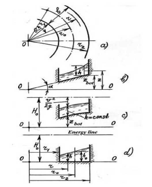
Fig.1 – Turning position parts of the water transmission structure: a) Turning plan; b) straight-bottomed sloping streams; с) streams of constant depth; d) streams with a horizontal bottom line
Since the above requirements have no effect on the third equation, it is written as follows::
- jz +
1 5p p 5z
= 0
Considering that the projection of the volumetric force acceleration on the z axis in equation (5) is jz = - g , we obtain this equation by integrating:
P = -P gz + C .
C - is an integral constant and is defined in the form C = pm + pgz0 by substituting the conditions p = Pat™ and z = z0 in the equation (6) on the free surface of the flow. When we write this in formula (6), the pressure at any point is found by the following formula:
P = Patm + Pg ( Z 0 — Z ) (7)
The bottom line, which is inclined in the curved part of the trough along the road, changes the flow parameters by creating an angle a = arctgk with respect to the horizontal line (Fig. 1, b), take into account the height of the location zbot = kz and the depth of the flow h = z 0 - zbot from the coordinate origin of any point of the bottom. Using the formula (7), the pressure at any point with coordinates (z, r) is determined as follows:
P = P atm + pg ( zbot + h - z ) = P atm + Pg ( kr + h — Z )
If we differentiate each side of the expression (8) according to the radius of the arbitrary point from the center of the curve, we obtain the following expression:
d p f , dh )
— = p g I k + I . d r I dr j
If we replace the expression (9) in (3):
u 2 dh
= g | k +:r I .
r v dr J
Differentiating the obtained equation (10), we obtain the following formula:
u 2
dh = — dr - kdr .
gr
In the polar coordinate system, the projection of the transverse velocity pressure at any point of the flow according to the angle of rotation in the turning section is determined as follows according to the scheme shown in Fig. 1, b:
т ^ = h о - ( h + kr ) (12)
2 g
Considering Equation (12) in expression (11):
2 ( H о - h - kr ) dh = —---------- dr - kdr ,
r or dh^ 2 (Hо - h) dr r
When the bottom line of the transverse section in the turning section of the water transmission structure forms an angle α with the horizontal line, if the depth of the flow in any radius r from the center of the curve "O" is h (Figure 1, b), the expression y = Ho -h (13) is given in the form of a differential equation:
dy + 2 y = 3 k (14)
dr r
The last expression can also be written as follows:
dy dr 3
— + 2— = — kdr . (15)
y ry
When we indefinitely integrate each side of equation (15), we obtain the expression for the depth
-
h by substituting the accepted expression for y in this equation:
C h = H0 - kr + 2 ,(16)
r where: C is an integral constant, taking into account the conditions r=r0 and h=h0 in equation (16) is found as follows:
C = kr-(Hо - ho) r0(17)
Substituting (17) for (16), we obtain the following expression for determining the depth h in an arbitrary radius r :
h = H о - kr + — [ kr o -( H 0 - h о ) r o ] = H о - kr + k • —2 -
2 r 0
+ о 2
r
тл r) i r Г0 _ и r Го r -
- H о • ~ + hо • T = H о 1--2 - kT"
r r ^ r J h = Hо
r
r
^“
3 r 0
2 r 0
+ о 2
r
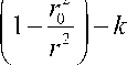
If the slope of the trough in turning section of the trough-type aquifer forms an angle α with the horizontal line, in the cross section with the coefficient k=tgα, indicating the tangent of this angle, the
^ 2
centrifugal acceleration, taking into account the radius r0 from the center of the curve is (Fig. 2) [27- r0
-
30] . Due to the fact that the centrifugal and release accelerations along the cross-section of the flow act in a direction perpendicular to the k - slope bottom line of the accelerating structure is [25-26]:
k = — (19)
gr 0
Fig. 2 – Schematic diagram of the cross-section at curved part of the water transmission structure with the bottom line inclined straight.
Given the expression (19) in (18), the relationship formula between the depth h of the flow at a random radius r from the center of rotation and the average velocity pressure is given in expression (20):
h = H о


• — 2
^ d ~ ,
2 g
where: ξ d - is the local loss coefficient in the transversely inclined part of the water transmission structures, calculated by the following formula:
^ = 2-- Г- . (21)
r 0 r
In the case under consideration (Figure 1, b), the bottom slope in the transverse direction of the structure:
k = dzbo^-dr
If we replace the expression (22) in the first of the formulas (13), we get:
2 1 H o - h - dz o- • r I dh I dr ) dz bot
= . dr r dr
If the free surface of the flow in the curve is convex and the depth is constant (h=const), the inner dh bottom line of the device is also convex (Fig. 1, c). In this case, given that — = 0 in Equation (23):
dr d-ot . 2 (H0 - h)
dr 3 r
Equation (24) can be written as follows:
12 dr
H - h -bot = 3 r
When we indefinitely integrate each side of the last equation, we get
H о - h
zbot =
— lnr + InC 3
where: is a C-integral constant, taking into account the conditions r=r 0 və z bot =z 0 in equation (26) is found as follows:
2 z 0
C = r 0"3 • eH" - h
Considering (27) in (26), we can write this equation as follows:
1 2
— ( Z bot - z о) = -ln
—о -h 3
If z 0 =0 , the point on the center line of the bottom of the structure coincides with the plane of comparison (O-O) and z bot from Equation (28) is found as follows:
zbot = 2 (—0 - h ) 1пГ . 3
If the inner bottom line is horizontal in the curved part of the water transmission structure (Fig. 1, d), then z bot = const and k = 0 . For this case, Equation (13) is expressed as follows:
dh^ 2 ( — о - h )
dr
r
Writing formula (30) on different sides of the equation according to the variables h and r :
dhdr
2,
—0 - hr
If we integrate, we get:
- In ( — 0 - h ) = 2ln- + lnC
Taking into account the integral constant C in equation (32), the conditions r=r 0 and h=h 0 in this equation, we find:
ln (—о - h )-1 = ln (O’); C = r - 1 ,(33)
_ r o " ( — о h 0 ) _|
If we replace the expression (33) in (32):
In(—0 -h)-In(—0 -h) = 2ln- + ln--2; —о---= -(34)
V о о- о - о —о -hо
If r=r crit , h 2 =h crit depth is formed and the flow rate at this depth is determined by the following expression:
u = u c-it = gh c-it^
In the curved part of the horizontal bottom line (z bot = const), the total pressure can be calculated by the following formula (Fig.1, d):
— о = hcn ,+ u c2-^ 0 crit
2 g
Taking into account the expression (35) in (36), we obtain the expression by the dependence of the depth of crisis on the full pressure:
— о h c:-tt +п (V Sh c-it ) 0 h crtt ; h c-it — о
2 g 2 3
When we replace h 0 with h crit and r 0 with r crit in expression (34), we obtain the following expression for the depth h from this equation:
H
^™
r crit
2 ; ' о
^“
2 r crit
3 1 - )
The last expression is determined by r crit :
Г — г • rcrit r
3 ( — о - h )
H 0
The average velocity along the depth h of the flow from the center of the bend to the radius r is determined from the expression of the total pressure (Fig. 1, d).
— о = h + u- ; u = 72 s ( — о - h )
As can be seen from expression (40), when h=0 , the velocity receives the maximum possible value:
u max = V2 g H 0
By multiplying the numerator and denominator of the square root expression in formula (39) by 2g , taking into account formulas (40) and (41), we obtain the following expression for r crit :
Г crit
2 g ( H o — h )
= V3 •.
2 gH 0
r = V3 • —— • r u max
Using the latter expression, it is possible to calculate
r
crit
when the average
u
, as well as
u
max
velocities at a depth
h
of radius
r
from the center of the bend of the water transmission structure are known, which gives an idea of the flow modes. Thus, if
r> r
crit
is in the horizontal position of the bottom line on the transverse section in the turning section of the water transmission structure, the flow is calm, and if
r
3 Results and Discussion
Thus, the expressions (12) ÷ (42) obtained in the considered issue allow to determine the hydraulic parameters and operating modes of the flow in the turning section of unpressurized transmission structure. As a result of the research, were obtained the main expressions by which the turning radius can be determined and compared with the critical parameters. Based on the analysis of the study, it is possible to plot the dependence of the radius and flow velocity in the turning part of the hydraulic flume. The dependence graph is shown in Fig. 3. As can be seen from the graph, if r>r
crit.
, the current is calm and this process corresponds to the coordinates between points A-B, if r
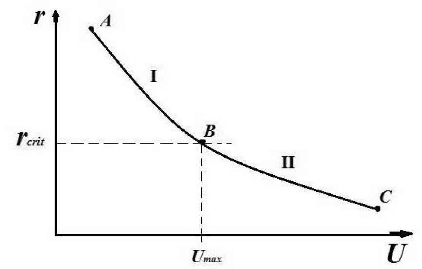
Fig. 3 - if r>rcrit., coordinates between A-B, flow is calm If r 4 Conclusions The issue of turbulent vortex motion of liquid in the rotary part of an open flume, which are widely used in hydraulic engineering construction, is considered. As a result of the research, it was found that with known parameters of fluid movement in the turning section of the flume with a radius, an average speed and a maximum speed in the depth of the channel, it is possible to determine critical radius as a result of which it is possible to form a position on the modes of fluid movement in free-flow open channels. Proceeding from this, it should be noted that along the vertical line of the transverse section of the turning part of the flume, if the radius big than critical radius, the flow will be calm, if the radius smaller than critical radius the flow will be violent. The proposed method for calculating the channel flow of a liquid makes it possible to determine the operating mode and hydraulic parameters of the liquid flow. In this article, the results obtained are as follows. 1. Arrangement of drainage tray structures in difficult foothill areas in order to reduce the volume of soil work. 2. Calculations have shown that in flumes it is possible to develop high flow rates exceeding the flow rate in conventional channels. 3. The results of the research make it possible to choose a more stable design, taking into account their durability and operational efficiency.
5 Acknowledgements Linear structures are widely used in hydraulic engineering construction, which include channels and trays. Canals are built in the soil environment and from this point of view, this design has a number of disadvantages - low water velocity due to channel erosion, - rapid settlement and difficulty in cleaning them from sediments. In connection with the expense, it is expedient to use concrete and reinforced concrete tray structures. The proposed article allows you to determine the main hydraulic parameters of the tray in the rotary part. That allows you to design them in difficult sections of the route and ensure the passage of high current velocities. At the same time, a reliable design can be designed, which will increase the service life and save money on repairs and maintenance.
6 Fundings As you know, the flow rate in open channels affects the reliability and stability of the structure. In the rotary part of the trays, the movement of liquid is accompanied by a turbulent flow. This leads to erosion of the riverbed. The method for calculating the main hydraulic parameters of the flow makes it possible to determine the critical radius in the turning sections. The application of these calculations allows you to choose the correct mode of fluid flow.
References Hydraulic flow in the turning section of unpressurized water transmission structure
- J.C.M. Gijs Hoffmans. (2022) “Influence of hydraulic flow regime in backward erosion piping”. Journal of Hydraulic Research. https://doi.org/10.1080/00221686.2021.2022027
- J.G.De Gijt (2019) “The Importance of Hydraulic Structures for Society: Quay Walls and Dikes in the Netherlands” Conference: Surabaya, Indonesia. https://DOI:10.9744/ced.17.3.179-186
- Michael Pfister, (2020) “Trajectories and air flow features of ski jump-generated jets”. Journal of Hydraulic research, Volume 52. https://DOI:10.1080/00221686.2013.875072
- E.E.Gasanov, V.V.Mammadova, A.J.Mammadov, V.H.Salimova, Kh.B.Salaeva. “Formation of rock slopes during work to reduce the erosion activity” Vol 2 №446 (2021). Page 45-54. ISSN 2224-5278. https://DOI:10.32014/2021.2518-170X.33
- G.H.Lim, P.S.K.Chua, Y.B.He. “Modern water hydraulics - the new energy - transmission technology in fluid power”. Applied energy journal, September-November 2003. Pages 239-246. https://doi.org/10.1016/S0306-2619(03)00064-3
- Grosan T., Postelnicu A., Pop I. Transport in Porous Media. 2016, vol. 81, pp. 89–103.
- E.I. Develskaya, A.V.Ivanov 2020 “Comparative analysis of models of channel deformations caused by thermal erosion on rivers” “Water resources” journal Vol47 №1 46-56 page. https://DOI:10.1134/S0097807820010054
- E.N.Dolgopolova, (2015) Regularities in the motion of water and sediments at the mouth of a river of estuarine-deltaic type: Case study of the Yenisei R “Water resources” journal Vol42 №2 198-207 page. https://doi.org/10.1134/S0097807815020050
- S.M.Vasilyev, A.I.Tishchenko, G.A.Senchukov, V.D.Gostishchev (2019) “Improved design of grade-control structure for reclamation canals of piedmont and mountain zones” Russian Scientific Research Institute of Land Improvement Problems, Novocherkassk, Russian Federation,Moscow 2019. “Ecology and Water management”, № 1(01), Pp.46–63
- Martin Rein (1998) “Turbulent Open-Channel Flows: Drop-Generation and Self-Aeration” ISSN: 0733-9429 Journal of Hydraulic Engineering. Published by American Society of Civil Engineers.
- Christopher Zoppou, Stephen G. Roberts (2000) “Catastrophic Collapse Of Water Supply Reservoirs In Urban Areas” ISSN: 0733-9429 Published by American Society of Civil Engineers
- Caterina Torres; Duncan Borman; Jorge Matos; David Neeve (2022) CFD Modeling of Scale Effects on Free-Surface Flow over a Labyrinth Weir and Spillway. Journal of Hydraulic Engineering. Volume 148 Issue.
- R.R.Chugaev “Hydraulic structures” Moscow 1985
- T.T.Rogovskiy “Workshop on mechanization, organization and production of hydraulic works” Moscow 1960
- V.P.Nedrigi “Hydraulic structures” Moscow 1983
- M.Grisihin “Hydraulic structures” Moscow 1962
- I.M.Volkov, P.F.Kononenko, I.K.Fedichkin “Hydraulic structures” Moscow 1962
- V.S. Lapshenkova “Design of Hydraulic structures” Moscow 1989
- A.V.Karaushev “Hydraulic of rivers and reservoirs” Leningrad 1955
- A.A.Uginchus, E.A.Chugaeva “Hydraulic” Leningrad 1971
- R.R.Chugaev “Hydraulic” Leningrad 1982
- Y.Z.Aleshkov “Waves motion of fluid” Vestnik of Saint-Petersburg University №10 Vol2
- Rajvanshi S. C., Wasu S. Int. J. of Applied Mechanics and Engineering. 2017, vol. 18, pp. 491–502. 3. Leont'ev N. E. Izvestiya RAN. Mechanical fluid and gas [Proceedings of RAS. Liquid and gas mechanics]. 2014, no. 4, pp. 107–112.
- Taktarov N. G. Izvestiya RAN. Mechanical fluid and gas [Proceedings of RAS. Liquid and gas mechanics]. 2016, no. 5, pp. 133–138.
- Vereshchagin V.P., Subbotin Y.N., Chernykh N.I. On the mechanics of helical flows in an ideal incompressible no viscous continuous medium // Proceedings of the Steklov Institute of Mathematics. 2014. V. 284, N 1. P. 159–174
- Dritschel D.G. Generalized helical Beltrami flows in hydrodynamics and magneto hydrodynamics // Journal of Fluid Mechanics. 2006. V. 222. P. 525–541.
- Rothstein J. P. Annu. Rev. Fluid Mech. 2016, vol. 42, pp. 89–102.
- Andreev V.K., Kaptsov O.V., Pukhnachov V.V., Rodionov A.A. Applications of group-theoretical methods in hydrodynamics. Dordrecht; Boston; London: Kluwer Acad. Publ., 1998.
- B.A. Jitovskiy, N.N.Rozanov “Swirling fluid flows and their use in hydraulic structures”. Vestnik. RUDN, 2001 №1 page 79-84.
- B.A. Jitovskiy, “Spillway and interface structures with swirl” RUDN, 2005 №1 page 190-196.
