Impact of TCSC on Distance Protection Setting based Modified Particle Swarm Optimization Techniques

Author: Mohamed Zellagui, Abdelaziz Chaghi
Journal: International Journal of Intelligent Systems and Applications(IJISA) @ijisa
Article in issue: 6 vol.5, 2013.
Free access
This paper presents the application of the Modified Particle Swarm Optimization (MPSO) technique for optimal settings zones for MHO distance relay protect 400 kV single transmission line of Eastern Algerian transmission networks at Algerian Company of Electrical and Gas (Group Sonelgaz) compensated by series Flexible Alternative current Transmission System (FACTS) i.e. Thyristor Controlled Series Capacitor (TCSC) connected at midpoint. The effects of TCSC insertion on the total impedance of a protected transmission line with respect to injected variable reactance value (X_(TCSC)) in capacitive and inductive boost mode depending of the firing angle (α) is considered. The modified setting zone protection for three zones (Z_(1), Z_(2) and Z_(3)) is have been investigate in order to prevent circuit breaker nuisance tripping and improve the performances of distance relay protection. In this work our aim is to compare the performance of the proposed MPSO algorithm with an analytical method (AM). The findings demonstrate the outstanding performance of the proposed MPSO in terms of computation speed, rate of convergence, and feasibility. The simulation results are compared with each other, and then the more perfect algorithm is considered.
TCSC, Apparent Reactance, Distance Protection, Settings Zones, Optimization, PSO Techniques
Short address: https://sciup.org/15010427
IDR: 15010427
Text of the scientific article Impact of TCSC on Distance Protection Setting based Modified Particle Swarm Optimization Techniques
Published Online May 2013 in MECS
In recent years, power demand has increased substantially while the expansion of power generation and transmission has been severely limited due to limited resources and environmental restrictions. As a consequence, some electrical transmission lines are heavily loaded and the system stability becomes a power transfer-limiting factor. FACTS controllers have been mainly used for solving various power system steady state control problems [1].
There are two generations for realization of power electronics based FACTS controllers: the first generation employs conventional thyristors switched capacitors and reactors, and quadrature tap-changing transformers while the second generation employs gate turn-off (GTO) thyristors switched converters as voltage source converters (VSCs). The first generation has resulted in the Static Var Compensator (SVC), the Thyristor Controlled Series Capacitor (TCSC), and the Thyristor Controlled Phase Shifter (TCPS) [2,3]. The second generation has produced the Static Synchronous Compensator (STATCOM), the Static Synchronous Series Compensator (SSSC), the Unified Power Flow Controller (UPFC), and the Interline Power Flow Controller (IPFC) [4]. The two groups of FACTS controllers have distinctly different operating and performance characteristics. In the presence of series FACTS devices, the conventional distance relay characteristics such as MHO and quadrilateral are greatly subjected to mal-operation in the form of overreaching or under-reaching the fault point [5,6]. Therefore, the conventional relay characteristics may not work properly in the presence of FACTS device.
Application of PSO technique in power system protection, reported in references [7,8] study the optimal coordination of overcurrent relays using a Modified Particle Swarm Optimization (MPSO) on transmission line. In [9,10] the application a Hybrid Particle Swarm Optimization (H-PSO) technique for optimal coordination of overcurrent relays is presented. The authors in references [11-14] study the application Nelder-Mead Particle Swarm Optimization (NM-PSO) technique for optimal coordination of overcurrent protection. In reference [15] the authors present an adaptive optimal relay coordination scheme for distributed generation based PSO technique, and optimal coordination of overcurrent relays by Mixed
Genetic (MG) and PSO Algorithm and comparison of both is reported in [16].
PSO application technique for transformer protection is reported in [17] where the transformer protection is based on Chaos PSO technique using dissolved gas value as a feature parameter and creates a power transformer fault detection model by support vector machine classifier. In reference [18, 20] applied PSO method trained by ANN algorithm for power transformer differential protection is presented and in reference applied PSO based probabilistic neural network for power transformer protection an algorithm has been developed around the theme of the conventional differential protection of transformer. It makes use of ratio of voltage to frequency and amplitude of differential current for the determination of operating conditions of the transformer.
For motor protection, the authors in paper [21] give a thermal protection technique by applying PSO technique to thermally protect three phases’ induction motors that are being successively starting, from operating beyond the IM thermal limits. This approach is implemented with PSO so as to determine the number of starting and operating times versus the IM thermal capability. This leads to a great improvement in the industry of thermal protection relays, where the output of the modeled induction motor is fed to a developed PSO program to find the optimal number of operating cycles regarding the duration of the duty cycle, the thermal capability is the main limitation for the number of starting cycles.
The effect of compensator TCSC on distance protection of transmission lines has been reported for general research on the influence of TCSC on the transmission lines protection in references [22-24] while the impact on communication-aided distance protection schemes and its mitigation is reported in [25]. Authors in reference [26] study this impact on numerical relay using computational intelligence based ANN method. In reference [27], the impedance measured ( Zseen ) by distance relay for inter phase faults with TCSC on a double transmission line high voltage is being studied and in [28], the variation of Zseen by distance relay for inter phase faults in presence of TCSC on adjacent transmission line by considering MOV operation is investigated. The effects of voltage transformers connection point on Zseen at relaying point for inter phase faults is reported in reference [29]. Comparing TCSC placements on double circuit line at mid-point and at ends from Zseen point of view is mentioned in reference [30].
The authors report in [31] a comparative study of GCSC and TCSC effects on MHO distance relay setting in single 400 kV Algerian transmission line. In reference [32] the authors is study the impact of TCSC on Zseen by MHO distance relay on 400 kV Algerian transmission line in presence of phase to earth fault based analytical method, and in reference [33]
modified setting numerical distance protection of transmission line 400 kV in presence TCSC using IEC 61850 communication protocol is reported. However, there is no work reported on mitigation of the impact of midpoint TCSC compensated transmission lines on distance protection.
In this paper two techniques : AM and MPSO for setting zones of an MHO distance protection on a 400 kV single transmission line installed in Algerian electrical networks in presence TCSC are investigated.
-
II. Apparent Reactance Injected by Thyristor Controlled Series Capacitor (TCSC)
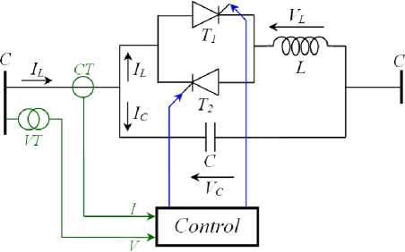
The series compensator TCSC mounted on figure 1.a is a type of series FACTS compensators. It consists of a capacitance ( C ) connected in parallel with an inductance ( L ) controlled by a valve mounted in antiparallel thyristors conventional ( T1 and T2 ) and controlled by an extinction angle ( α ) varied between 90° and 180°.
(a)
(b)
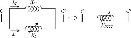
Fig. 1: Transmission line with TCSC system. (a). System configuration, b). Apparent reactance.
This compensator injects in the transmission line a variable reactance ( XT CSC ) indicated by figure 6.b. Its value is function of the line reactance X L where the device is located. The apparent reactance XT CSC is defined by the following equation [34, 35, 36]:
XTCsc (a) = Xc. [1 — A + B ]
Where,
. K2 ^ о + sin(o)A =
K2 -11 п
А =
L.C
R 4. K2 2Г о
B = cos
K 2- 1 ( 2
And, о = 2.(п - а)
.
K .tan
The о is a part of a cycle during which a thyristors valve is in the conducting state and the firing angle a is the time expressed in electrical angular measure from the capacitor voltage ( VC ) zero crossing to the starting of current conduction through the thyristors valve [36]. The curve of X TCSC as a function of angle a is divided into three different regions which are inductive, capacitive and resonance as shows in figure.2.
K=А
to
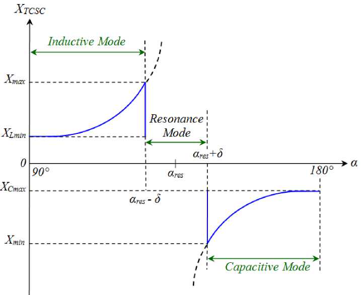
Fig. 2: Characteristic curve X tcsc = /(a) for TCSC.
The Vernier mode allows the TCSC to behave either as a continuously controllable capacitive reactance or as a continuously controllable inductive reactance. It is achieved by varying the thyristors firing angle in an appropriate range. However, a smooth transition from the capacitive to inductive mode is not permitted because of the resonant region between the two modes [34, 37]. A variant of this mode is the capacitive vernier mode, in which the thyristors are fired when the capacitor voltage and capacitor current have opposite polarity.
This condition causes a TCR current that has a direction opposite to that of the capacitor current, thereby resulting in a loop-current flow in the TCSC controller. Another variant is the inductive vernier mode, in which the TCSC can be operated by having a high level of thyristors conduction. In this mode, the direction of the circulating current is reversed and the controller presents net inductive impedance.
-
III. Settings Zones for Distance Relays Protection
-
3.1 Selectivity protection
Since the impedance of a transmission line is proportional to its length, for distance measurement it is appropriate to use a relay capable of measuring the impedance of a line up to a predetermined point (the reach point). Such a relay is described as a distance relay and is designed to operate only for faults occurring between the relay location and the selected reach point thus giving discrimination for faults that may occur in different line sections [37-39].
The basic principle of distance protection involves the division of the voltage at the relaying point by the measured current. The apparent impedance so calculated is compared with the reach point impedance.
If the measured impedance is less than the reach point impedance, it is assumed that a fault exists on the line between the relay and the reach point as shown in figure 3.
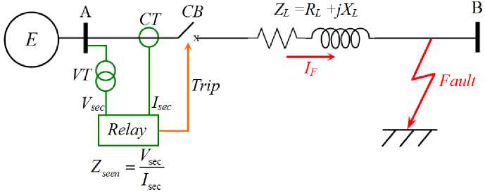
Fig. 3: Principle operation for distance protection
Time selectivity protection is given by the staggered trip time depending on the distance between measurement point and the fault [37, 38], [40].
Following the setting philosophy of the distance protection in Sonelgaz group, three zones (Z1, Z2 and Z3) are considered [41]: The first zone covers about 80% of the protected transmission line AB and trips the circuit breaker in t1.
The second zone extends to 100% of the protected line AB and 20% of the adjacent line and trips circuit breaker in the t 2 while the third zone extends to 100% of the protected line AB+40% of the adjacent line and trips the circuit breaker in the t 3 as indicated in figure 4.
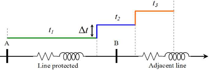
Fig. 4: Selectivity of distance protection.
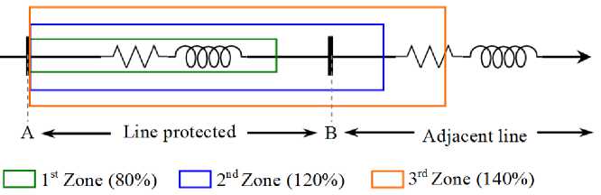
Fig. 5: Settings zones of distance protection.
-
3.2 Setting zones
Line impedances are proportional to the line lengths and this property is used to calculate the distance from the relay location to the fault. The relay, however, is fed with the current and voltage measured signals from the primary system via current transformers (CT) and voltage transformers (VT). Therefore, the secondary measured value by relay is used for the setting and is obtained by the following expression:
Z,^ = Zab-l = [(Rl + jX )-l] (k k J
Where,
k
I pri
' CT т sec
k
V pri
and,
'VT v sec
The setting zone of distance zone for transmission line is indicated by figure 5.
The setting zones for protected electrical transmission line without series FACTS i.e. TCSC is [40, 41]:
is initialized with a population of random solutions, called particles.
Unlike in the other evolutionary computation techniques, each particle in PSO is also associated with a velocity. Particles fly through the search space with velocities which are dynamically adjusted according to their historical behaviors. Therefore, the particles have a tendency to fly towards the better and better search area over the course of search process.
Where, Z L-AB and Z L-BC is real total impedance of line AB and BC respectively. K VT and K CT is ratio of voltage and current respectively. The characteristic curves X ( R ) for MHO distance relay are represented in figure 6.
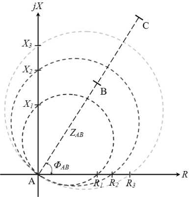
Fig. 6: Characteristic curves of MHO distance relay.
Z 1 — 0, 8. [ R AB + JXAB + JXtcsc ( a ) ]
Z 2 — R ab + JX ab + JX tcsc ( a ) + 0,2.( R bc + JX bc ) (13)
3 AB AB TCSC , . BC BC ) (14)
-
4.1 Original particle swarm optimization algorithm
The original PSO algorithm is discovered through simplified social model simulation. PSO was introduced by Kennedy and Eberhart [43, 44], has its roots in swarm intelligence. The motivation behind the algorithm is the intelligent collective behavior of organisms in a swarm (e.g., a flock of birds migrating), while the behavior of a single organism in the swarm may seem totally inefficient. The bird would find food through social cooperation with other birds around it.
PSO represents an optimization method where particles collaborate as a population to reach a collective goal. Each n-dimensional particles xi is a potential solution to the collective goal, usually to minimize a function f . Each particle in the swarm can memorize its current position that is determined by evolution of the objective function, velocity and the best position visited during the search space referred to the personal best position ( pbest ), this search is based on probabilistic, rather than deterministic, transition rules. A particle x i has memory of the best solution y i that it has found, called its personal best ; it flies through the search space with a velocity v i dynamically adjusted according to its personal best and the global best ( gbest ) solution y’ found by the rest of the rest of the swarm (called the gbest topology) [45-47].
Let i indicate a particle’s index in the swarm, such that, S = { x1, x2, ..., xs } is a swarm of s particles. During each iteration of the PSO algorithm, the personal best yi of each particle is compared to its current performance, and set to the better performance. If the objective function to be minimized is defined as function f. R " > ' , then [48].
^ xi t) if f ( xi t) )< f ( У( t-1))
Traditionally, each particles velocity is updated separately for each dimension j, with:
-
IV. Particle Swarm Optimization (PSO) Technique
PSO technique based approach is considered as the one of the most powerful methods for solving the nonsmooth or smooth global optimization problems [42, 43]. PSO is the population based search algorithm and
vit;1) — wvC + ci.ri.(pbest'j't* -xi,^)
+ c 2 . r 2 . ( gbest S - x it) )
The stochastic nature of the algorithm is determined by r 1 and r 2 , two uniform random numbers between zero and one. These random numbers scaled by acceleration coefficient c 1 and c 2 . The inertia weight w was introduced to improve the convergence rate of the PSO algorithm [46-48].
Usually, the value of the velocity is clamped to the range: [- vmax , vmax ] to reduce the possibility that the particle might fly out the search space. If the space is defined by the bounds: [ x min , x max ], then the value of v max is typically set so that:
v max
h.x
. max
Where 0,1 ≤ h ≤ 1 [49]. After that, each particle is allowed to update its position using its current velocity to explore the problem search space for a better solution as follows:
.( t +1)
i , j
( t ) ( t )
i , j i , j
The search mechanism of the PSO using the modified velocities and position of individual i based on equations (16) and (18) is shows in figure 7.
the possibility of finding an optimal or close to optimal solution.
The original PSO is therefore modified to overcome the aforementioned problems. Initializing the pickup currents randomly does this, thus the problem becomes linear and the reactance injected by TCSC values is calculated using the interior point method. The initial feasible solutions are then applied to the PSO algorithm.
The method is implemented to handle constraints of the relay coordination optimization problem and is found to be more efficient while updating the solution into a feasible solution (inductive and capacitive operation mode).
If any particles of an individual violate its constraints then it is fixed to its maximum/minimum value (cut down value of XTCSC ) according to its objective function minimum/maximum.
This method is used for handling the constraints for modified particle swarm optimization to solve MHO distance relay coordination.
xk if satidfying constraints
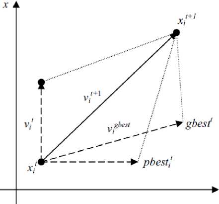
Fig. 7: Search mechanism of the PSO technique.
k
k i ,min
xk i ,max
if no satidfying constraints (max)
if no satidfying constraints (min)
The PSO or MPSO algorithm doesn’t require any initial feasible solution for iterations to converge instead the initial position of the particles generated randomly for the MPSO is considered.
The particles positions are then verified with the constraints before passing it to the objective function for optimization. Thus there is no need of the penalty value calculation. It reduces the time and increase the convergence rate also [50]. The velocity update in MPSO is taken care of by inertia weight w, usually calculated with the following if-then-else statement:
if iterm „ < iter .then max
-
4.2 Modified particle swarm optimization algorithm
The standard PSO algorithm is used for unconstrained optimization tasks. PSO in its standard form is not capable of dealing with the constrained optimization problem like relay coordination of distance relay. The repair algorithm gives the PSO algorithm capability of tackling the coordination constraints imposed on the relays, while searching for an optimal setting three zones.
The PSO algorithm also has limitation in terms that, during the updating process, where each particle modifies its position, the resultant particle position could be outside the feasible search space. This reduces w =
ML — ML min max
iter„ — 1 max
. ( iter - 1 ) + w max
else w = ■ min
The inertia weight starts at wmax and its functional value in equation (17) reduces as the number of iterations increases till itermax (maximum iteration count) and after that maintains a constant value of wm i n for remaining iteration. Where the wmax and wm i n are the maximum and minimum weight value that are constant and itermax is maximum iteration [51].
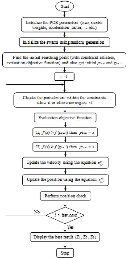
Figure 8 represent the flow chat for the MPSO algorithm used to calculate the optimal setting three zones ( Z 1 , Z 2 , and Z 3 ) of the MHO distance relay.
Stop
Start
| Evaluation objective function j
________________________i_______________________, Ц /to >/(?»"■) then pu»i = x
[ Ц /to >№=) Чип g^; = x ]
Yes
Find the initial searching point (with constraint satisfies. evaluation objective function) and also get initial рь#» and gs».-
Checks the particles are within the constraints allow it or otherwise reelect it
" 4
Initialize the swarm using random generation
Update the position using the equation x,"'
Update the velocity using the equation v"1
Display the best result (Zt, Zs, Zs)
Perform position check
Fig. 8: Flow Chart of MPSO technique proposed.
-
V. Case Study and Simulation Results
The power system studied in this paper is the 400 kV Algerian electrical transmission networks at group Sonelgaz (Algerian Company of Electrical and Gas) which is shows in figure 9 [52, 53]. The MHO distance relay is located in the busbar at Ramdane Djamel substation to protect transmission line between busbar A and busbar B respectively at Ramdane Djamel and Oued El Athmania substation in Mila. The busbar C is located at Salah Bay substation in Sétif.
The TCSC is installed in midline where maximum injected voltage V TCSC is equal 20 kV and maximum reactive power Q TCSC is +80 / -10 MVar. The parameters of transmission line are summarized in the annexes.
Figure 10 show the XTCSC characteristics curves on two modes inductive and capacitive mode as function of the firing angle ( α ) of the TCSC used in case study.
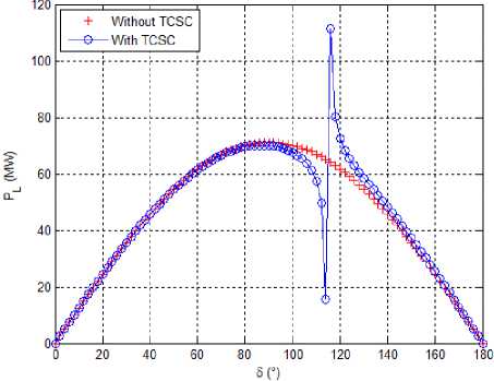
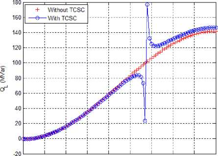
The figures 11.b and 11.b show the impact of TCSC insertion (capacitive and inductive modes) on the active and reactive power variation of PL and QL transited respectively with angle line ( δ ) varied between 0° to 180°.
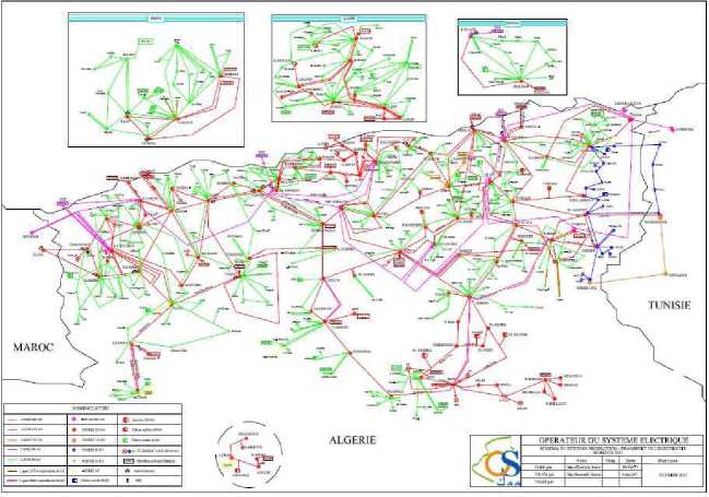
Fig. 9: Electrical networks study in presence TCSC.
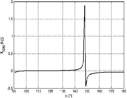
Fig. 10: Characteristic curve X TCSC ( α ).
Table 1: Settings Zones without TCSC based AM.
|
Settings |
Zones of Protection |
||
|
Zone 1 |
Zone 2 |
Zone 3 |
|
|
Reactance ( Ω ) |
72,00 |
99.50 |
109,00 |
|
Resistance ( Ω ) |
1,7467 |
2,4139 |
2,6443 |
-
5.2 Settings zones based analytical method
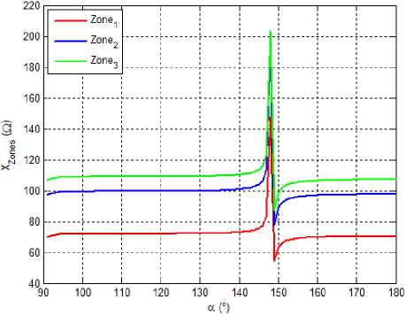
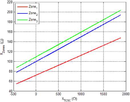
Figures 12.a and 12.b represented the impact of the parameters of TCSC on the settings three zones reactance ( X1 , X2 and X3 ) respectively for MHO distance relay based AM.
(a)
(a)
О 20 40 60 80 100 120 UO 160 180
а (■)
(b)
Fig. 11: Impact of TCSC on power transmission line. a). Active power P L ( δ ), b). Reactive power Q L ( δ ).
(b)
Fig. 12: Settings zones reactance with respect to α and X TCSC . a). X Zones = f ( α ), b). X Zones = f ( X TCSC ).
-
5.1 Settings zones without TCSC
The total impedance measured by the distance relay without TCSC is: ZL = 43,668 + j 1800 ( Ω ), the settings zones are summered in table 1.
2.5 -
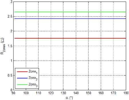
Figures 13.a and 13.b represented the impact of the parameters of TCSC on the settings three zones resistance ( R 1 , R 2 and R 3 ) respectively for MHO distance relay based analytical method.
(a)
§
2 --
0.5
О*—
-500
500 1000
W^)
(b)
Fig. 13: Settings zones resistance with respect to α and X TCSC . a). R Zones = f ( α ), b). R Zones = f ( X TCSC ).
-
5.3 Settings zones based MPSO technique
The specified parameters for the proposed algorithm are summered in the appendix. The testing data of the proposed MPOS algorithm to calculate the setting distance relay on two boost mode, i.e. Inductive and capacitive are indicated respectively in table 2.a in table 2.b with their percentage error (ε) between the accurate values based AM and the estimated based MPOS.
Table 2: Setting Zones for Distance Relay based MPOS.
a). Inductive Mode
|
а (°) |
||||||
|
95 |
115 |
125 |
135 |
145 |
147 |
|
|
X i (П) |
68,710 |
69,0418 |
69,1219 |
69,843 |
72,111 |
79,0112 |
|
R i (П) |
1,6731 |
1,67396 |
1,67404 |
1,6838 |
1,6661 |
1,6647 |
|
ε r (%) |
4,2098 |
4,1642 |
4,1596 |
3,5995 |
4,6128 |
4,6931 |
|
X 2 (П) |
96,109 |
96,1131 |
96,321 |
97,034 |
100,01 |
109,127 |
|
R 2 (П) |
2,3396 |
2,33050 |
2,3332 |
2,34080 |
2,3214 |
2,3285 |
|
ε r (%) |
3,0789 |
3,4546 |
3,3430 |
3,0280 |
3,8315 |
3,5358 |
|
Х з (П) |
105,124 |
105,541 |
105,241 |
105,433 |
109,491 |
118,88 |
|
R 3 (П) |
2,5582 |
2,5591 |
2,5495 |
2,54460 |
2,5509 |
2,5636 |
|
ε r (%) |
3,2559 |
3,2195 |
3,5830 |
3,7700 |
3,5301 |
3,0494 |
b). Capacitive Mode
|
а (°) |
||||||
|
149 |
155 |
160 |
165 |
170 |
180 |
|
|
X i (П) |
53,111 |
68,011 |
69,021 |
69,143 |
67,711 |
68,011 |
|
R i (П) |
1,7043 |
1,7188 |
1,7248 |
1,7210 |
1,6824 |
1,6874 |
|
ε r (%) |
2,4268 |
1,5935 |
1,2497 |
1,4685 |
3,6800 |
3,3931 |
|
Х 2 (П) |
75,109 |
93,113 |
93,321 |
94,034 |
95,013 |
96,127 |
|
R 2 (П) |
2,3382 |
2,3439 |
2,3254 |
2,3348 |
2,3554 |
2,3799 |
|
ε r (%) |
3,1351 |
2,8964 |
3,6629 |
3,2740 |
2,4231 |
1,4077 |
|
Х з (П) |
86,124 |
103,54 |
103,24 |
104,43 |
105,49 |
105,51 |
|
R 3 (П) |
2,6164 |
2,5978 |
2,5665 |
2,5877 |
2,6101 |
2,6074 |
|
ε r (%) |
1,0523 |
1,7549 |
2,9409 |
2,1401 |
1,2925 |
1,3925 |
As can be seen, application of the MPO technique for 3, 0280 and 4,6931 from table 2.a and between 1,05238
optimal new settings results in the error varied between and 3,68004 from table 2.b.
-
5.4 Comparison and interpretations
Table 3 presents a comparison between the proposed and usual algorithms for two operations mode (inductive and capacitive). In the proposed algorithm, it is obvious that the execution time and iteration numbers is lesser than usual algorithm, where texe is the execution time and N I ter is the number of iterations.
proposed method can be adopted for determining the optimum settings of zones.
For future research, the application a new hybrid MPSO trained by ANN multiple layers (PSO-ANN) to minimize the execution time, number of iterations and error can be investigated.
Table 3: Comparison between AM and MSOP Method.
a). Inductive Mode
|
Method |
AM |
MPSO |
||
|
a (°) |
t exe (sec) |
N Iter |
t exe (sec) |
N Iter |
|
95 |
1541 |
542 |
93 |
61 |
|
115 |
1498 |
476 |
82 |
55 |
|
125 |
1382 |
381 |
74 |
47 |
|
135 |
1254 |
239 |
61 |
32 |
|
145 |
1193 |
191 |
52 |
28 |
|
147 |
1106 |
147 |
43 |
19 |
b). Capacitive Mode
|
Method |
AM |
MPSO |
||
|
a (°) |
t exe (sec) |
N Iter |
t exe (sec) |
N Iter |
|
149 |
1608 |
768 |
143 |
81 |
|
155 |
1543 |
643 |
126 |
61 |
|
160 |
1441 |
539 |
97 |
52 |
|
165 |
1389 |
378 |
81 |
43 |
|
170 |
1233 |
266 |
69 |
38 |
|
180 |
1104 |
197 |
54 |
26 |
It is clear from simulation results in table 3, the other advantages of MPOS as compared with AM, the proposed MPSO is capable of controlling the variation angle α and reactance X TCSC permanently which is an advantage in calculating new settings zones of the network at a very high speed with an acceptable error.
-
VI. Conclusion
This paper analyzes and demonstrates the modified particle swarm optimization algorithm application associated with protective distance relay for 400 kV protected transmission line in presence of TCSC compensator witch affects three settings zones. MPOS techniques could be used as an effective tool for realtime and implement digital relaying purposes. This might allow distance relay work more accuracy and precision.
In this paper also a new MPOS algorithm is proposed in terms of computation speed, rate of convergence, and objective function value for reduction in the distance relay operating time. The results demonstrate that the
References Impact of TCSC on Distance Protection Setting based Modified Particle Swarm Optimization Techniques
- K.K. Sen, and M.L. Sen, Introduction to FACTS Controllers: Theory, Modeling and Applications, published by John Wiley & Sons, Inc., and IEEE, New Jersey, USA, July 2009.
- X.P. Zhang, C. Rehtanz, and B. Pal, Flexible AC Transmission Systems: Modelling and Control, published by Springer Publishers, Heidelberg, Germany, June 2006.
- E. Acha, C.R. Fuerte-Esquivel, H. Ambriz-Pérez, and C. Angeles-Camacho, FACTS Modelling and Simulation in Power Networks, published by John Wiley & Sons Ltd, London - UK, April 2004.
- R.M. Mathur, and R.K. Varma, Thyristor-Based FACTS Controllers for Electrical Transmission Systems, Published by John Wiley & Sons, Inc. Publication ant IEEE Press, USA, June 2002.
- P.K. Dash, A.K. Pradhan, and G. Panda, Apparent Impedance Calculations for Distance Protected Transmission Lines Employing Series-Connected FACTS Devices, Electric Power Components and Systems (EPCS), Vol. 29, No. 7, 2001, pp. 577-595.
- P.K. Dash, A.K. Pradhan, G. Panda, and A.C. Liew, Digital Protection of Power Transmission Lines in The Presence of Series Connected FACTS Devices, IEEE/PES Summer Meeting, Washington, USA, pp. 1967-1972, 19 July, 2000.
- H. Qu, Q. Jia, and Z. Bo, MPSO based Protective Relay Coordination for Micro-Grid, 10th IET International Conference on Developments in Power System Protection (DPSP), Manchester - UK, 29 March - 1 April 2010.
- H. Zeineldin, E. EI-Saadany, and M. Salama, Optimal Coordination of Overcurrent Relays using a Modified Particle Swarm Optimization, Electric Power Systems Research, Vol. 76, No. 11, 2006, pp. 988-995.
- Y. Damchi, H.R. Mashhadi, J. Sadeh, and M. Bashir, Optimal Coordination of Directional Overcurrent Relays in a Microgrid System using a Hybrid Particle Swarm Optimization, International Conference on Advanced Power System Automation and Protection (APAP), Beijing - China, 16-20 October 2011.
- M. Bashir, M. Taghizadeh, J. Sadeh, and H.R. Mashhadi, A New Hybrid Particle Swarm Optimization for Optimal Coordination of Overcurrent Relay, International Conference on Power System Technology (POWERCON), Hangzhou - China, 24-28 October 2010.
- L. An, and Y. Ming-Ta, Optimal Coordination of Directional Overcurrent Relays Using NM-PSO Technique, International Symposium on Computer, Consumer and Control (IS3C), Taichung - Taiwan, 4-6 June 2012.
- An Liu, and Ming-Ta Yang, A New Hybrid Nelder-Mead Particle Swarm Optimization for Coordination Optimization of Directional Overcurrent Relays, Mathematical Problems in Engineering, Volume 2012, pp. 1-18, 2012.
- M.R. Asadi, and S.M. Kouhsari, Optimal Overcurrent Relays Coordination using Particle Swarm Optimization Algorithm, IEEE/PES Power Systems Conference and Exposition (PSCE), Seattle - USA, 15-18 March 2009.
- M. Mansour, F. Mekhamer, and N. El-Sherif, A Modified Particle Swarm Optimizer for the Coordination of Directional Overcurrent Relays, IEEE Transaction on Power Delivery, Vol. 22, No.3, July 2007, pp. 1400-1410.
- M. El-Saadawi, A. Hassan, and M. Saeed, Adaptive Optimal Relay Coordination Scheme for Distributed Generation, International Journal of Distributed Energy Resources, Vol. 7, No. 2, 2011, pp.79-91.
- A. Motie Birjandi, and M. Pourfallah, Optimal Coordination of Overcurrent Relays By Mixed Genetic and Particle Swarm Optimization Algorithm and Comparison of Both, IEEE International Conference on Workshop of Signal, Image Processing and Applications (ICSIPA), Kuala Lumpur - Malaysia, 16-18 November 2011.
- H. Han, and H. Wang, Study on Power Transformer Protection based on Chaos Particle Swarm Optimization, 10th IEEE International Conference on Electronic Measurement & Instruments (ICEMI), Chengdu, 16-19 August 2011.
- M. Tripathy, Optimal Radial Basis Function Neural Network Power Transformer Differential Protection, IEEE Bucharest Power Tech, Romania, June 28-July 2, 2009.
- M. Geethanjali, S. Mary Raja Slochanal, and R. Bhavani, PSO Trained ANN based Differential Protection Scheme for Power Transformers, Journal Neuro-Computing, Vol. 71, No. 4-6, January 2008, pp. 904-918.
- M. Tripathy, R.P. Maheshwari, and H.K. Verma, "Particle Swarm Optimization Based Probabilistic Neural Network for Power Transformer Protection", IEEE International Conference on Industrial Technology (ICIT), India, 15-17 December 2006.
- N. El-Amary, F. Ezzat, Y. Mostafa, and W. Ghoneim, Thermal Protection for Successively Starting Three Phase Induction Motors using Particle Swarm Optimization Technique, 11th International Conference on Environment and Electrical Engineering (EEEIC), Venice - Italy, 18-25 May 2012.
- M. Khederzadeh, and T.S. Sidhu, Impact of TCSC on the Protection of Transmission Lines, IEEE Transactions on Power Delivery, Vol. 21, No.1, January 2006, pp. 80-87.
- Q. Liu, Z. Wang, and Y. Xu, Study on the Influence of TCSC on Fault Component Distance Protection, IEEE Transmission and Distribution Conference & Exhibition: Asia and Pacific, China, 23-25 August 2005.
- P.A. Kulkami, R.M. Holmukhe, K.D. Deshpande, and P.S. Chaudhari, mpact of TCSC on Protection of Transmission Line, International Conference on Energy Optimization and Control (ICEOC), Maharashtra, India, 28-30 December 2010.
- T.S. Sidhu, and M. Khederzadeh, TCSC Impact on Communication Aided Distance Protection Schemes and Mitigation, IET Conference on Generation, Transmission and Distribution, Vol. 152, No. 5, September 2005, pp. 714-728.
- A. Hosny, and M. Safiuddin, ANN based Protection System for Controllable Series Compensated Transmission Lines, IEEE/PES Power Systems Conference and Exposition, Seattle, USA, 15-18 March 2009.
- S. Jamali, A. Kazemi & H. Shateri, Measured Impedance by Distance Relay for Inter Phase Faults with TCSC on a Double Circuit Line, 18th Australasian Universities Power Engineering Conference (AUPEC), Sydney, Australia, 14-17 December 2008.
- S. Jamali, A. Kazemi, and H. Shateri, Measured Impedance by Distance Relay for Inter Phase Faults in Presence of TCSC on Next Line, IEEE Region 10 Conference (TENCON), 19-21 November 2008.
- S. Jamali, A. Kazemi, and H. Shateri, "Measured Impedance for Inter Phase Faults in Presence of TCSC Considering MOV Operation", IEEE Canada Electric Power Conference (EPEC), Canada, 6-7 October 2008.
- A. Kazemi, S. Jamali, and H. Shateri, Measured Impedance by Distance Relay with Positive Sequence Voltage Memory in Presence of TCSC, IEEE/PES Power Systems Conference and Exposition (PSCE), Seattle, USA, 15-18 March 2009.
- M. Zellagui, and A. Chaghi, A Comparative Study of GCSC and TCSC Effects on MHO Distance Relay Setting in Algerian Transmission Line, International Journal of Engineering and Technology (IJET), Vol. 2, No. 2, Feb. 2012, pp. 220-228.
- M. Zellagui, and A. Chaghi, Impact of TCSC on Measured Impedance by MHO Distance Relay on 400 kV Algerian Transmission Line in Presence of Phase to Earth Fault, Journal of Electrical Systems (JES), Vol. 8, No.3, Sept. 2012, pp. 273-291.
- M. Zellagui, and A. Chaghi, Modified Setting Numerical Distance Protection of Transmission Line in Presence TCSC using IEC 61850 Communication Protocol, ACTA Technica Napocensis - Electronics and Telecommunications, Vol. 53, No. 3, Sept. 2012, pp. 16-24.
- IEEE Standard 1534, "IEEE Recommended Practice for Specifying Thyristor Controlled Series Capacitor", IEEE Power and Energy Society, New York, USA, 20 November 2009.
- N. Christl, R. Hedin, P.E. Krause, P. Luetzelberger, M. Pereira, K. Sadek, and D.R. Torgerson, Advanced Series Compensation (ASC) with Thyristor Controlled Impedance, International Conference CIGRE’ 1992, Session, SC, Paris, France, October 1992.
- S.G. Jalali, R.A. Hedin, M. Pereira, and K. Sadek, A Stability Model for the Advanced Series Compensator (ASC), IEEE Transactions on Power Delivery, Vol. 11, No. 2, April 1996, pp. 1128-1137.
- E.V. Larsen, K. Clark, S.A. Miske, and J. Urbanek, Characteristics and Rating Considerations of Thyristor-Controller Series Compensation, IEEE Transactions on Power Delivery, Vol. 9, No. 2, 1994, pp.1018-1027.
- G. Zigler, Numerical Distance Protection: Principles and Applications, Third Edition, published by Publics Corporate Publishing, Germany, 2008.
- J.L. Blackburn, T.J. Domin, Protective Relaying: Principles and Applications, Third Edition, Published by CRC Press and Taylor & Francis Group, USA, 2006.
- M. Zellagui, and A. Chaghi, Distance Protection for Electrical Transmission Line: Equipments, Settings Zones and Tele-Protection, published by LAP Publishing, Germany, June 2012.
- N. Manamani, Principles and Settings of Distance Relay, Group Sonelgaz, Training at GRTE Sétif, Group Sonelgaz, Algeria, 15 June 2009.
- Y. Shi, and R. Eberhart, A Modified Particle Swarm Optimizer, IEEE International Conference on Evolutionary Computation (ICEC), Alaska, USA, 4-9 May 1998.
- J. Kennedy, and R. Eberhart, Particle Swarm Optimization, IEEE Neural Networks Conference, Piscataway, NJ, USA, 1995.
- J. Kennedy, and R. Eberhart, A New Optimizer using Particle Swarm Theory, 6th International Symposium on Micromachine and Human Science, Nagoya, Japan, 1995.
- J. Kennedy, Small Worlds and Mega Minds: Effects of Neighborhood Topology on Particle Swarm Performance, Conference of Evolutionary Computation (CEC), Washington, USA, 6-9 July, 1999.
- J. Kenney, R.C. Eberhart, and Y. Shi, "Swarm Intelligence", Morgan Kaufmann Publishers, San Francisco - USA, March 2001.
- J. Kenney, and R. Mendes, Population Structure and Particle Swarm Performance, IEEE World Congress on Computational Intelligence, proceedings of the Congress on Evolutionary Computing (CEC). Honolulu, USA, 12-17 May 2002.
- F. Van Den Bergh, and A.P. Engelbrecht, A New Locally Convergent Particle Swarm Optimizer, IEEE International Conference on Systems, Man and Cybernetics, Hammamet, Tunisia, October 6-9, 2002.
- F. Van den Bergh, and A.P. Engelbrecht, A Cooperative Approach to Particle Swarm Optimization, IEEE Transactions on Evolutionary Computation, Vol. 8, No. 3, pp. 225-239, June 2004.
- J.B. Park, K.S. Lee, J.R. Shin, and K.Y. Lee, A Particle Swarm Optimization for Economic Dispatch with Non-Smooth Cost Functions, IEEE Transaction on Power System, Vol. 20, No. 1, 2005, pp. 34-42,
- Shu-Kai S. Fan, and Z. Erwie, A Hybrid Simplex Search and Particle Swarm Optimization for Unconstrained Optimization, European Journal of Operational Research (EJOR), Vol.181, No. 2, Sep. 2007, pp.527-548.
- M. Zellagui, and A. Chaghi, A Comparative Study of Impact Series FACTS Devices on Distance Relay Setting in 400 kV Transmission Line, Journal of Electrical and Electronics Engineering (JEEE), Vol.5, No. 2, October 2012, pp. 111-116.
- Sonelgaz Group/OS, Topologies of Electrical Networks High Voltage, technical rapport, Algeria, 30 December 2011.
