Impact response of steel fiber reinforced concrete beams with hooked fibers

Author: Khan M.A., Jafri M.Sh.
Journal: Строительство уникальных зданий и сооружений @unistroy
Article in issue: 4 (109), 2023.
Free access
The object of research is to investigate the impact response and structural behavior of steel fiber reinforced concrete (SFRC) at varying percentages of fibers by weight of concrete. The impact resistance of plain concrete is low, mainly due to low energy dissipating features and inadequate tensile strength. Steel fibers in concrete mix compensate for the weak tensile properties of conventional concrete.
Concretes, sfrc, strength, stress-strain curves, impact loads, drop hammer, mechanical properties, strain energy
Short address: https://sciup.org/143182696
IDR: 143182696 | UDC: 69 | DOI: 10.4123/CUBS.109.3
Text of the scientific article Impact response of steel fiber reinforced concrete beams with hooked fibers
Steel reinforcing bars are an old method of strengthening concrete against impact loads. Steel rebars successfully preserve the integrity of the structure of the concrete target by preventing the mass from separating from the concrete [1]. However, this method did not reduce penetration depth upon projectile contact [2]. As a result, other approaches have been proposed for increasing concrete's capacity to disperse energy. A large number of steel fibers and a strong concrete matrix are advantageous for boosting the concrete's capacity to survive impacts since both can absorb a significant portion of the energy given during an impact [3]–[5].
The concrete material is brittle, and tiny fibers can be blended and spread uniformly throughout the concrete matrix to incorporate ductility. Fiber bridging over fractures can assist in enhancing ductility and avoid sudden failure. Fiber-reinforced concrete (FRC) is also recognized for its high impact resistance [6]–[9].
Numerous researchers have extensively studied the impact and durability of steel fiber-reinforced concrete (SFRC) beams concerning the insertion of fibers. The following literature review pertains to the impact, workability, compressive strength, tensile strength, torsional strength, and Modulus of elasticity of SFRC.
Zhang et al. [10] examined various mechanical properties of plain and fiber-reinforced lightweight aggregate concrete, including flexural toughness, impact resistance, density, compressive and tensile strength, and Modulus of elasticity. The author investigates the impact of the density of coarse and fine Khan, M.A.; Jafri, M.S.
Impact response of steel fiber reinforced concrete beams with hooked fibers;
aggregates on their flexural toughness and impact resistance. The construction material utilized in this context consisted of expanded clay, lightweight aggregate, and steel fibers. The material's impact resistance was evaluated using an instrumented drop-weight testing apparatus. The compressive strength of lightweight aggregate concrete ranges from 40 to 80 megapascals. The study's findings indicate that plain concrete's impact resistance was improved by incorporating steel fibers and attaining high levels of compressive strength and density.
In their study, Song et al. [11] employed the drop weight test technique to assess the impact resistance of steel fiber-reinforced concrete. The researchers used hooked-end fibers with a length of 35 mm and a diameter of 0.55 mm. The results indicate that steel-fiber concrete exhibited superior initial cracking, ultimate failure, and post-impact residual strength when compared to non-fibrous concrete.
In 2009, Mohammadi et al. [12] conducted a study on the impact resistance of steel fiber-reinforced concrete that incorporated mixed aspect ratio fibers. The evaluation of impact loads was conducted on a total of 108 beam specimens, measuring 100 mm (width), 100 mm (depth), and 500 mm (length), made of plain concrete and SFRC. The sample consisted of corrugated steel fibers with varying percentages of 1.0%, 1.5%, and 2.0%. The composite specimens in each volume fraction were composed of a combination of 0.6% and 2.0% with 25 mm and 50 mm steel fibers in varying proportions. The dropweight impact testing involved the recording of the number of hammer blows required to initiate the initial visible crack and subsequent failure of the specimen. The presented data displays the number of impacts and the corresponding energy exerted during the initial cracking and eventual complete failure of the specimen. The concrete sample with a volume fraction of 2.0% of long fibers exhibited superior performance under impact stress.
The study conducted by Mindess and Zhang [13] investigated the behavior of high-strength fiber-reinforced concrete when subjected to uniaxial compressive impact stress. A drop-weight impact machine that was equipped with instrumentation was utilized to conduct tests on fiber-reinforced concrete (FRC) systems that exhibited compressive strengths ranging from 60 MPa to 120 MPa. The deformations of FRC cylinders were measured using high-speed video cameras. The compressive strength was observed to increase in accordance with the predicted trend as the drop height (or impact velocity) was increased. The dynamic compressive toughness was enhanced by an increase in drop height and matrix strength. The failure mode of FRC was contingent upon various parameters such as the matrix, fiber, and drop height.
In 2013, a study conducted by Yazici et al. [14] investigated the mechanical properties of concrete reinforced with steel fibers at varying volume percentages of 0.5%, 1.0%, and 1.5%. The investigation revealed that there were reductions in the compressive and splitting tensile strengths of SFRC due to mechanical losses following an impact. A volume fraction of 1.5%. Structural Fiber Reinforced Composites (SFRCs) demonstrated superior performance when subjected to impact stress. The impact fracture energy of steel fiber reinforced concrete (SFRC) is reported to be 3–23 times higher than that of conventional concrete.
The investigation of Yoo et al. [15] aimed to analyze the flexural performance of beams made of steel-fiber-reinforced concrete (SFRC) subjected to quasi-static and impact loads. The study involved the production and assessment of SFRC beams with varying compressive strengths (fc' of approximately 49, 90, and 180 MPa) and fiber volume fraction contents (vf of 0, 0.5, 1.0, and 2.0%). In the context of quasi-static loading, it was observed that augmenting the fiber content and strength led to a concomitant increase in the flexural strength, deflection capacity, and toughness. The augmentation of potential energy, strength, and fiber content has been observed to enhance the impact load-bearing capacity and post-peak behavior.
Jafri and Israil authored a publication in 2015 [16] to investigate the performance of composite beams composed of M20-grade concrete mix measuring 100 mm x 100 mm x 500 mm, subjected to flexure and direct compression while varying the fiber content. Cylindrical fibers with a length of 28 mm and a diameter of 0.28 mm, possessing an aspect ratio of 100, were employed in this study. The fibers were of a straight configuration and were subjected to varying weight percentages. The experiment involved testing simply supported beams subjected to flexure and direct compression loads of 0, 50, 100, and 125 kN. All sets of three beams underwent testing using the four direct compression values for every percentage of fiber content. Empirical findings indicate that the ultimate bending strength and deflection exhibit an upward trend in response to compression while maintaining a constant proportion of fiber content. Compression increases the ductility of a certain proportion of fibers. The process of compression has been observed to improve the ultimate bending strength and ultimate central deflection of beams across the board. An increase in ultimate bending strength is observed with the addition of up to 0.75% fiber for every direct compression value. The inclusion of fibers results in a reduction of ultimate flexural strength across all levels of direct compression. A fiber percentage beyond 0.75% exhibits a positive impact on the ultimate bending strength and center deflection of beams without compression. The increase in beam compression and percentage of fibers results in a corresponding increase in the central deflection at the ultimate load. The ductility, toughness, and crack resistance of SFRC specimens were evaluated. The equations are used to predict the occurrence of cracking and the ultimate torque to improve the design of lightweight concrete subjected to torsional loading.
Zia and Ali [17] authored a publication that showed that seepage, which accounts for 20–30% of the total water loss, is the most significant water loss that canals experience. The implementation of concrete lining in canals results in a reduction in seepage. Conventional sections of cement-concrete exhibit a seepage rate of approximately 15-20%. The mechanical properties, water absorption, and linear shrinkage of Jute Fiber Reinforced Composites (JFRC), Nylon Fiber Reinforced Composites (NFRC), and Polypropylene Fiber Reinforced Composites (PPFRC) were evaluated through experimental methods in accordance with the standards set forth by the American Society for Testing and Materials (ASTM). The PC mix comprised a ratio of 1:3:1.5:0.7 for cement, sand, aggregate, and water, respectively. Fibers of length 50 mm were blended with polycarbonate (PC) in an amount of 5% by cement mass. Results indicate reduced strength in compression and enhanced flexural and split tensile strengths. Durability properties such as linear shrinkage and water absorption were also improved.
Sun et al. [18] examined the uniaxial mechanical properties of concrete reinforced with steel fibers (SFRC) subjected to compressive stress at high strain rates. Specimens of steel fiber reinforced concrete (SFRC) were produced and analyzed, with varying steel fiber volume fractions of 0.0%, 0.75%, 1.5%, 3.0%, 4.5%, and 6.0%. This study examined the impact of strain rate and fiber reinforcement on the dynamic behavior of plain concrete and steel fiber-reinforced concrete (SFRC).
In 2017, Tan and Mansur [19] conducted central point-load experiments on twelve square slabs to evaluate the punching shear capacity of steel fiber-reinforced concrete (SFRC) slabs in the absence of steel bar reinforcement. Various multi-hook fibers were examined in conjunction with concrete compressive strength, reinforcing index, and slab thickness. The statistical evaluation of two techniques for forecasting the punching shear capacity of SFRC slabs that lack traditional reinforcement was conducted. Flexure was primarily responsible for the primary mode of failure in the slabs, and yield line theory correctly predicted the slabs' load-bearing capacity. It was found that the strength of SFRC continues to improve even at fiber volume exceeding 3%.
The study conducted by Naraganti et al. [20] aimed to investigate the impact resistance of structural concrete that incorporates sisal fibers, polypropylene (PP), and steel fibers. The impact resistance of hybrid fiber reinforced concrete (HyFRC) was evaluated through experimentation with the incorporation of steel polypropylene (S-PP) and steel sisal (S-Si) fibers. The study incorporated varying levels of fiber dosages, specifically 0%, 0.50%, 1%, 1.25%, and 1.5%. The ACI Committee 544 was followed to conduct tests on the drop weight and compressive strength for a duration of 7, 28, and 90 days. The impact resistance of FRC was found to be enhanced with an increase in its fiber content. Among monolithic fiber-reinforced composites, SFRC exhibited the most favorable performance, whereas Sisal FRC (SiFRC) demonstrated the least favorable performance. The experimental results indicate that S-Si HyFRC exhibits superior performance compared to sisal FRC. Moreover, optimal performance was observed in HyFRC with S-PP at a 1.5% fiber dosage.
In 2019, Zhao et al. [21] introduced an innovative and uncomplicated approach to anticipate the maximum response of reinforced concrete beams under impact loading, utilizing the contact law, the principle of energy conservation, the impulse-momentum theorem, and the wave theory. The forcedeflection correlation of the reinforced concrete beam is computed through conventional beam theory and the widely recognized layered-section methodology. The maximum midspan deflection of reinforced concrete beams subjected to impact loading is determined by the conservation of energy approach, which considers the strain rate effect. The proposed methodology effectively predicts the maximum midspan deflection of reinforced concrete beams subjected to impact loading, utilizing a dataset of 143 impact experiments. The use of an anti-impact design can effectively leverage the marginally exaggerated maximum impact force to avert shear failure in the vicinity of the impact location.
Zhou et al. [21] employed a domestic, advanced ultrahigh-duty drop-weight impact testing machine system to assess two sets of reinforced concrete beams at low velocity. This study investigates the influence of varying impact velocity and mass on the dynamic response of reinforced concrete (RC) beams, as well as the alterations in local and global damage while maintaining a constant impact energy. The ABAQUS finite element software is employed to generate a numerical model that accounts for material strain rate, with the aim of corroborating and extending experimental findings. The present experiment reveals that, under equivalent energy conditions, the maximum impact force displays an upward trend with increasing impact velocity. However, the mid-span displacement and rebar strain exhibit an initial rise followed by a subsequent decline. Furthermore, it has been observed that (i) the beam sustains the most severe damage when subjected to an impact velocity of 2.25 m/s and an impact mass of 400 kg; (ii) the peak value of cumulative impact force, mid-span displacement, and rebar strain are more significantly influenced by the impact velocity as compared to the mass; and (iii) a decrease in impact velocity (increase in mass) results in a reduction in local damage of the beam, but an overall increase in damage is observed. The failure mode of the beam transitions from localized punching shear to overall static failure.
Jabir et al. [21] authored a scholarly work. Ultra-high-performance concrete (UHPC) is a fibrous cementitious composite that exhibits remarkable strength, ductility, toughness, and durability. Their investigation focused on the capacity of ultra-high-performance fiber-reinforced concrete (UHPFRC) to withstand multiple impacts. A total of 72 Ultra-High Performance Fiber Reinforced Concrete (UHPFRC) disc specimens underwent testing through a modified repeated drop mass impact test. A total of six compilations, each consisting of twelve discs, were created using the specimens. Although the mixture components remained constant, the fibers employed varied. Polypropylene fibers measuring 6 mm and 15 mm in length were employed in the study. Each of the mixes contained 2.5% volumetric fibers, albeit with varying compositions of the three types of fibers. The micro-steel fiber mixes with a diameter of 15 mm exhibited a higher resistance to shattering under impact compared to other mixtures. The blend consisting solely of 2.5% 15-mm micro-steel fiber exhibited the highest impact resistance, surpassing the other mixtures by 25–140%. The impact resistance of UHPC cracking was evaluated at various levels of dependability by means of analyzing the Weibull distribution.
Lam et al. [22] conducted tests on fiber-reinforced and wrapped cylindrical specimens. Copper-plated steel fibers were mixed in ultra - high-performance concrete (UHPC) mix at 2% by volume. The fiber length was 13 mm, with a diameter of 0.2 mm. The maximum unconfined compressive strength was 151.1 MPa, and the confined strength was 155.7 MPa, indicating an improvement in confinement with changes in failure types. That suggests a carbon fiber polymer is also useful for studying structural strengthening in light of failure modes, such as the study of Khan [23].
The effects of fiber type and content on ultra-lightweight high-strength concrete (ULHSC) with a specific strength of more than 30 kPa/kg-3 were investigated in the study of Zhang et al. [24]. This research looks at the dynamic compressive response and failure mechanism of ULHSC with different fiber compositions. Impact testing was carried out with a 100-mm splitting Hopkinson pressure bar apparatus and strain rates ranging from around 20 s-1 to 120 s-1. The results showed that the tested ULHSC with one vol% end-hooked steel fiber maintained a great balance of dynamic strength and density.
Under varying strain rates, the impacts of nanomaterials and steel fibers on failure patterns, dynamic compressive strengths, and impact toughness of UHPC were examined by Huang et al. [25]. The results suggest that optimum nanomaterial addition can improve the axial compression impact characteristics of UHPC. By adding 2% nano-CaCO3, the dynamic compressive strength and impact toughness of UHPC were enhanced by 10.05% and 5.70%, respectively, at a strain rate of 160 s-1.
Therefore, upon conducting a thorough literature review, it was determined that there were certain research gaps. Specifically, while a significant number of studies have been conducted utilizing M30 and M40 concrete grades, there is a lack of research on M20 and M25. Numerous investigations have been carried out regarding the aspect ratio of fibers, with approximately 80 studies conducted in this area. However, there is a scarcity of research on aspect ratios of approximately 60. Numerous investigations have been carried out using a reduced mass of the hammer and an increased height of free fall. Numerous investigations have been carried out to enhance the impact resistance of fiber-reinforced concrete through the utilization of the fiber fraction by volume of concrete. However, limited research has been conducted on the implementation of fiber fraction by weight of concrete.
In view of the above, the following are the objectives of the present study:
-
(i) To determine the number of blows having the same energy, which the beams take before failure.
-
(ii) To determine the strain energy of SFRC beams before failure.
-
(iii) To determine the maximum deflection of the beams with the same concrete grade having
varying percentages of fibers.
-
(iv) To observe the crack pattern generated on the SFRC beam due to impact load.
-
2 Materials and method
-
2.1. Materials
To perform this experiment, 24 SFRC cubes 150 mm x 150 mm x 150 mm, cylinders of 150 mm diameter and 300 mm long, and beams of cross section 100 mm x 100 mm and of length 500 mm were cast of two different grades of concrete mixes viz. M20 and M25 with fiber contents (0%, 0.5%, 1%, and 1.5% ) by weight of concrete and equivalent volume fractions (0%, 0.17%, 0.33% and 0.5%, respectively) of the concrete; that is, by volume of concrete it will be 1/3rd of the values calculated by weight of concrete. The concrete mixes were designed as per IS:10262-2019. The material was weighed dry and placed for mixing with a trowel before water was added to the dry mix. The fibers were fully blended in the dry mix. Oil was applied on the inside surface of the mold before casting, and concrete was poured in stages. It was ensured that the concrete was correctly laid and compacted. The specimens were then placed in water for 28 days to cure before being taken from their molds after 24 hours of casting.
-
The results of cubes of mixes after 28 days of curing, mix ratio along with water cement ratio used are given in Table 1. The properties of steel hooked fibers of Fig. 1 selected for the study are listed in Table 2. The steel fibers are mixed in the beams with varying proportions, i.e., 0%, 0.5%, 1%, and 1.5%.
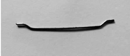
Fig. 1 - Hooked Ended Steel Fiber
Table 1. Properties of concrete mix
|
Concrete grade |
Mix (by weight) |
w/c ratio |
Avg. compressive Strength (Mpa) 28 days |
|
M20 |
1:1.85:3.40 |
0.55 |
25.48 |
|
M25 |
1:1.66:3.05 |
0.5 |
26.37 |
Table 2. Properties of Steel Hooked Fiber
|
Properties |
Values |
|
Aspect ratio l/d ratio |
64 |
|
Length (mm) |
35 |
|
Diameter (mm) |
0.55 |
|
Unit Weight |
78.6 kN/m3 |
|
Ultimate Tensile Strength |
>1200 MPa |
|
Material |
Low Carbon Drawn Wire |
|
Appearance |
Clear and Bright with hook-end anchorage |
-
2.2. Method
-
2.2.1. Theoretical calculations
/ E
Specimens were cast using standard molds. The material was weighed dry and placed for mixing by using a trowel, and then water was added to the dry mix. Fibers were mixed thoroughly. Then, specimens were immersed for curing in potable water for 28 days. After 24 hours (setting time) of casting, all the specimens were removed from their mold.
In the present experimental program, cubes, and cylinders were used to identify material properties in compression and tension, respectively. The cubes were tested under uniaxial compression. Two dial gauges were used for the measurement of contraction displacement. The split tensile test is used to measure the tensile strength of the concrete. A compressive line load along the length of a concrete cylinder placed with its axis horizontal between the compressive platens is applied.
The moment of inertia for all beams is 41.67x105 mm4. The Modulus of elasticity is evaluated using the following equation from IS456:
E eq = 5000 ^
The strain energy due to impact load is calculated by the relation obtained by integrating the energy equation (2) for a typical sketch shown in Fig. 2:
1 M 2
U = dx
2} E I eq cr
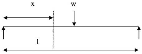
Fig. 2 - Beam denoting dimensions used in equation (2)
W
Where, M = —. x .
On putting the value of M in equation (2) and solving equation (3):
U = W L
96 EI eq cr
This is the equation used for the calculation of strain energy.
2 PH
In the above equation, W is equivalent static load in kN is given as
.
Where,
P H 5 Icr
is 0.254 kN (25.90 kg, for hammer), is 0.165m (height of fall), denotes Max deflection of beam L = 0.4 m (effective span), is the moment of inertia of the cracked section,
Eeq is the elasticity modulus of the section.
wl 3
Theoretical deflection is calculated as
48 EI
.
-
2.2.2. Test setup
The beam to be tested was clamped in an Impact Hammer Testing Machine with the help of a steel rod of diameter 20 mm and plates of thickness 12 mm. The steel rod had threads at its ends, which were fastened by bolts. Proper care was taken at the time of the experiment to avoid the loosening of bolts by wrapping the cotton thread on rods. Wooden packing was also put in to avoid any type of slippage. Fig. 3 shows the experimental arrangement having a beam clamped with rods and plates.
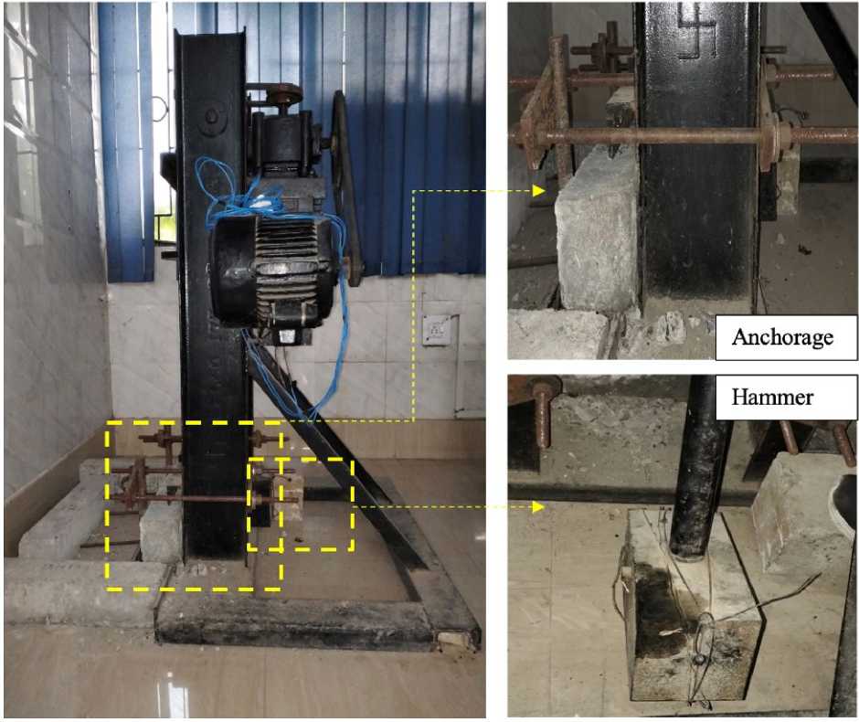
Fig. 3 - Impact Hammer Testing Machine on the left, identifying anchorage system and hammer.
The impact test on the concrete beam was done with the help of an impact hammer of the equivalent mass of 25.4 kg. The impact hammer was initially lifted and then allowed to fall freely under gravity to strike the beam placed horizontally. The hammer was lifted manually and was anchored to a wooden trigger, from where it was dropped by pushing the trigger aside. The position of the trigger was properly marked so that every time the hammer was dropped, the height of the fall would remain constant.
-
3 Results and Discussion
-
3.1. Results
-
3.1.1. Compressive strength
-
-
M20 Cubes with Fibers (0%, 0.5%, 1%, and 1.5%): In the case of cubes of grade M20, when the cubes were tested under uniaxial compression, the compressive strength was found to be 25.48 MPa (reference value) when no fibers are added. After adding 0.5%, 1%, and 1.5% fiber to the M20 grade cubes, the corresponding compressive strength decreased by 15.42%, then increased by 28.49% and decreased by 17.46% respectively, refer to fig. 4a.
The value of the peak compressive strain of M20 cubes without fibers is 5.425x10⁻³ (reference value), and after adding 0.5%, 1%, and 1.5% fibers, the corresponding peak compressive strain decreases by 32.25%, then increases by 29.49% and finally decreases by 17.51% respectively against cubes of without fibers.
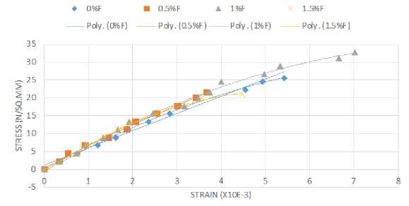
M25 Cubes with Fibers (0%, 0.5%, 1%, and 1.5%): In the case of cubes of grade M25, when the cubes were tested under uniaxial compression, the compressive strength was found to be 26.37 MPa (reference value) when no fibers were added. After adding 0.5%, 1%, and 1.5% fiber to the M25 grade cubes, the corresponding compressive strength decreases by 4.78%, 2.84%, and increases by 21.88%, respectively, refer to Fig. 4b.
The value of the peak compressive strain of M25 cubes without fibers is 6.520x10⁻³ (reference value), and after adding 0.5%, 1%, and 1.5% fibers, the corresponding peak compressive strain decreases by 31.5%, 7.82%, and increases by 37.46% respectively against cubes of without fibers.
a)
♦ 0%F ■ 0.5% F A 1%F X 1.5% F
---Poly.(C%F) ----Poly.(Q5%F)----Poly.(l%F) ----Poly.(15%F)
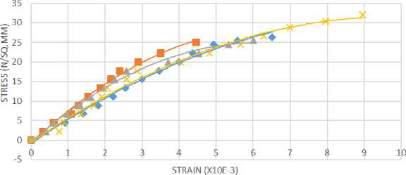
b)
Fig. 4 - Combined stress-strain curves for cubes with Fibers (0%, 0.5%, 1%, and 1.5%): a - M20 cubes; b - M25 cubes
Corresponding to fiber content of 0%, 0.5%, 1%, 1.5%, the values of E for beams M20 are 25238 eq
N/mm2, 23210 N/mm2, 28609 N/mm2, 22929 N/mm2 and for beams M25 are 25675 N/mm2, 25054
N/mm2, 25308 N/mm2, 28350 N/mm2 respectively.
-
3.1.2. Split tensile strength
In tests on cylinders (fig. 5), uniform tensile stress is developed over nearly 2/3 of the loaded diameter due to the compression loading.
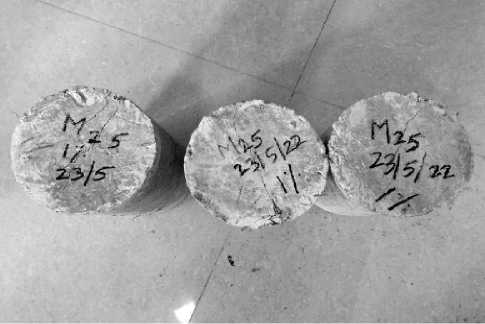
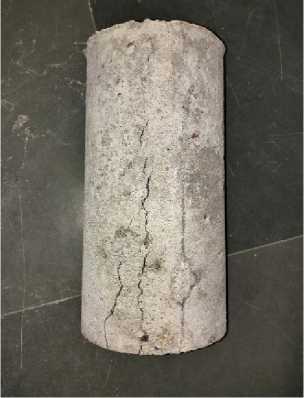
a) b)
Fig. 5 – Typical specimen from split tensile strength: a - Transverse cracks; b - Longitudinal cracks
The split tensile strength for different ratios of fiber content is presented in Fig. 6. For M20-grade cylinders, the split tensile strength of the cylinder is 1.66 MPa with 0% fiber content. The split tensile strength of the cylinder increases by 8.43%, 36.14%, and 47.59% with 0.5%, 1%, and 1.5% fiber content. For M25 cylinders, the split tensile strength of the cylinder is 2.36 MPa with 0% fiber content. This strength increases by 13.55%, 17.80%, and 29.23% with 0.5%, 1% and 1.5% fiber content.
■ M20 DM25
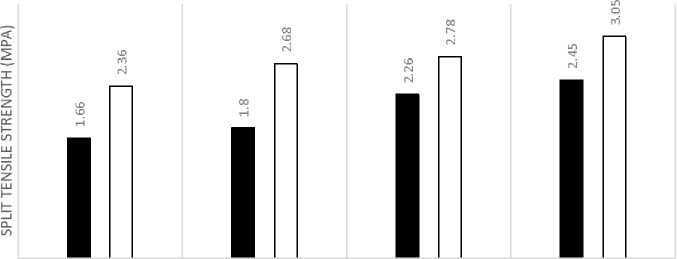
0% 0.50% 1% 1.50%
FIBRE CONTENT
Fig. 6 – Comparison of Split Tensile Strength of Cylinders with Fibers (0%, 0.5%, 1%, and 1.5%) for
M20 grade and M25 grade
3.1.3. Beams
The pattern of cracks developed in beams during the impact test is shown in Fig. 7 at the corresponding maximum deflections shown in Fig. 8.
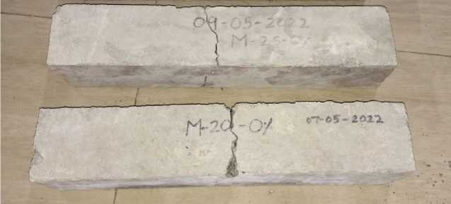
a)
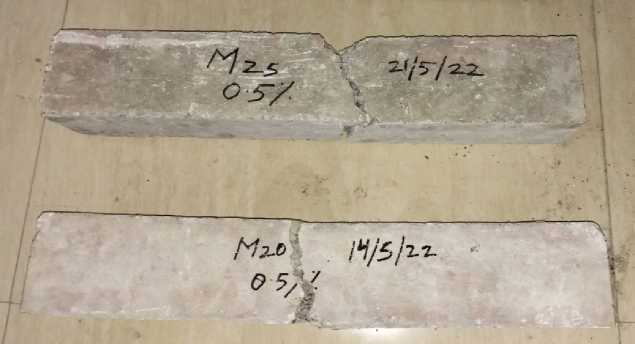
b)
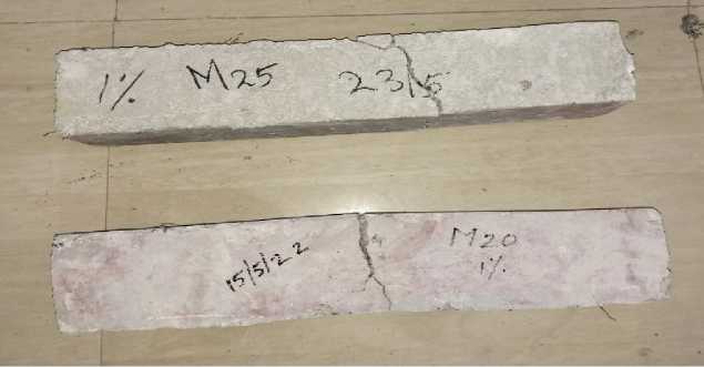
c)
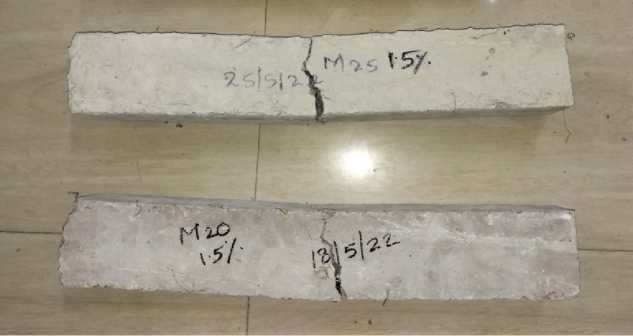
d)
Fig. 7 - Crack pattern of Beams M20 and M25 Concrete Grades with fiber content: a - 0%; b - 0.5%; c - 1%; d - 1.5%
■ M20 ПМ25
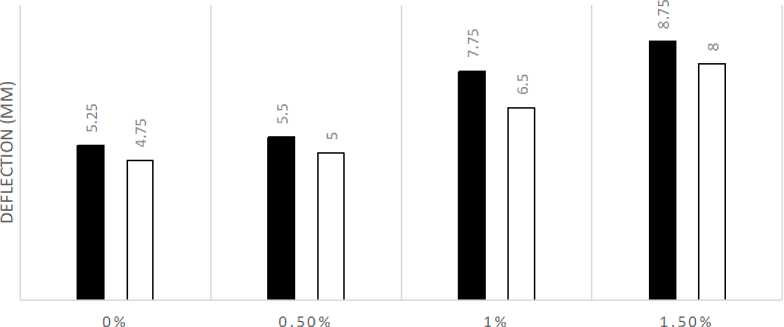
FIBER CONTENT
Fig. 8 - Comparision of maximum deflection of beams by increasing both concrete grade and fiber contents
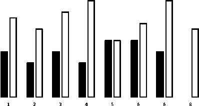
The corresponding maximum blows for M20 and M25 grades having fiber content of 0%, 0.5%, 1%, and 1.5% are recorded to be 3, 4, 7, 9 and 3, 4, 8, 10. The first crack appeared respectively at blow numbers 2, 3, 5, and 3, 3, 6, 8.
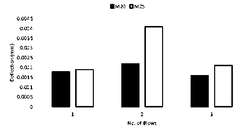
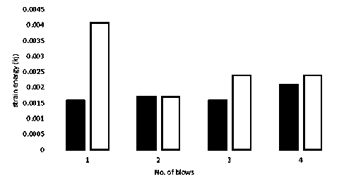
The max strain energy based on calculation is presented in Fig. 9. M25 grade concrete, for fiber contents of 1% and 1.5%, carried a higher number of blows. Additionally, compared to M20, relatively higher strain energy is sustained by M25 for any corresponding blow for a given fiber content.
b)
0.004
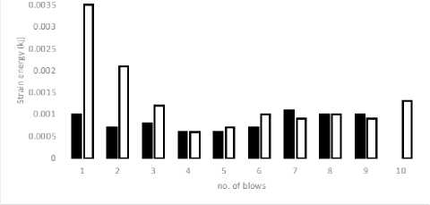
c) d)
Fig. 9 – Comparison of maximum strain energy of beam M20 and M25 concrete grades versus the number of blows with fiber content: a - 0%; b - 0.5%; c - 1%; d - 1.5%
-
3.2. Discussion
The M20 beam containing no fiber exhibited failure after enduring three impacts. The crack is detected upon the second impact and subsequently propagates, ultimately leading to failure. Mid-span failure is a common occurrence in beams, and it is notable that no observable cracking is present at the beam ends. The maximum deflection and maximum strain energy recorded were 5.25 mm and 0.00219 kJ, respectively.
The deflection of the beam exhibits a 5% increase from the initial to the final impact.
The M20 beam reinforced with 0.5% fiber exhibited failure after four impact blows. The initiation of the crack is detected upon the third impact, subsequently leading to its propagation and eventual failure. Mid-span failure is a common occurrence in beams, while the absence of cracks at the ends is typically observed. The maximum deflection and maximum strain energy recorded were 5.5 mm and 0.0021 kJ, respectively.
The deflection of the beam exhibits a percentage increase of 13.63% between the first and last blow.
The M20 beam reinforced with 1% fiber exhibited failure after undergoing seven blows. The fracture is detected upon the fifth impact and subsequently extends to result in structural breakdown. Mid-span failure is a common occurrence in beams, with no observable cracking at the ends. The maximum deflection and maximum strain energy recorded were 7.75 mm and 0.001 kJ, respectively.
The deflection of the beam did not experience any percentage increase from the first to the last blow.
The M20 beam has been reinforced with 1.5% fiber. Each of the beams required nine impacts before failure occurred. The fracture is detected upon the application of the seventh impact and subsequently advances, resulting in structural breakdown. Mid-span failure is a common occurrence in beams, with no observable cracking at the ends. The maximum deflection and maximum strain energy recorded were 8.75mm and 0.0011 kJ, respectively.
The deflection of the beam did not exhibit any percentage increase from the first to the last blow.
The beam M20, with a fiber content of 1.5%, exhibits a 200% increase in impact resistance capacity when compared to the beam M20, with a fiber content of 0%.
The M25 beam specimens devoid of any fiber reinforcement exhibited failure after undergoing three impact loads. The fracture is detected upon the second impact and subsequently propagates, resulting in structural failure. Mid-span failure is a common occurrence in beams, and it is typically not accompanied by any observable cracking at the ends. The maximum observed deflection and strain energies are 4.75 mm and 0.00414 kJ, respectively.
The deflection of the beam exhibits a percentage increase of 10.53% between the first and last blow.
The M25 beam has been reinforced with 0.5% fiber. Each of the beams required four impacts to reach failure. The crack is detected upon the third impact and subsequently propagates, leading to structural failure. Mid-span failure is a common occurrence in beams, with no visible cracks observed at the ends. The maximum deflection and maximum strain energy recorded were 5.0 mm and 0.0041 kJ, respectively.
The deflection of the beam exhibits a percentage increase of 23.52% from the first to the last blow.
The M25 beam reinforced with 1% fiber exhibited failure after eight impact cycles across all specimens. The fracture is detected upon the application of the sixth load cycle and subsequently propagates, resulting in structural failure. Mid-span failure is a common occurrence in beams, while the absence of any observable cracks at the ends is notable. The maximum deflection and maximum strain energy recorded were 6.5 mm and 0.0017 kJ, respectively.
The deflection of the beam exhibits a percentage increase of 8.33% between the first and last blow.
The M25 beam has been reinforced with 1.5% fiber. All of the beams required ten impacts to reach failure. The fracture is detected upon the application of the eighth load cycle and subsequently progresses, leading to structural failure. Mid-span failure is a common occurrence in beams, with no observable cracking at the ends. The maximum deflection and maximum strain energy recorded were 8.0 mm and 0.0035 kJ, respectively.
The deflection of the beam exhibits a percentage increase of 64.28% from the initial to the final impact.
The addition of 1.5% fiber to beam M25 results in a significant increase of 233.33% in its impactresisting capacity when compared to beam M25 without fiber.

-
4 Conclusions
Based on the research gaps in the literature on the topic, the key research objectives were identified and were the focus of the study, such as the impact tests on SFRC beams with M20 and M25 grades of concrete (as these concrete grades are more common in practice), the reduced aspect ratio of steel fiber (locally and easily available), and considering fiber fraction by weight rather than by volume (for ease of practice).
The method required to install a motorized hammer impact testing setup, such that a motor will raise the level of the hammer to a fixed height before releasing the hammer. The average mass of the lever and hammer would then fall to impact a simply supported beam. This process considered the total mass of the hammer-lever system to evaluate strain energy generated on the beam with each impact. Therefore, the number of blows was converted into strain energy sustained by beams, and the corresponding deflections were recorded to check changes in ductility.
Based on experimental testing of SFRC beams subjected to impact load, the following conclusions have been derived:
-
1- As the grade of concrete increases from M20 to M25, there is a corresponding increase in the number of blows required to induce failure. The findings indicate that the utilization of a higher grade of concrete can enhance the ability of beams to withstand impact loads.
-
2- The augmentation of fiber quantity in beam construction is directly proportional to the number of blows leading to failure. This suggests that the utilization of a greater number of fibers can enhance the capacity of beams to carry impact loads, and an optimum fiber content can be achieved for each concrete grade.
-
3- The maximum deflection achieved prior to failure exhibits a positive correlation with the quantity of steel, indicating that an increase in steel quantity results in a higher maximum deflection before failure. That is, the result indicates that there is a positive correlation between the amount of steel and the enhancement of beam ductility.
-
4- The maximum deflection achieved prior to failure exhibits a negative correlation with the rise in concrete grade. The findings suggest that the brittleness of concrete is positively correlated with its grade, albeit necessitating a greater number of blows to induce failure in beams constructed with higher-grade concrete.
-
5- In each instance, a crack emerged at the mid-span location, which ultimately resulted in the failure of the beams; that is, the failure is localized at the location of impact.
Overall, enhancing the grade of concrete (that is most common in practice) and augmenting the amount of steel fibers can enhance the capacity of beams to carry impact loads.
ABBREVIATIONS
Conc. = concrete
Max. = maximum
F = fiber
No. = number
Pt. = point
Def. = deflection
NOTATIONS b = width of the beam d = depth of the beam
Ec = elastic Modulus of concrete
E eq = elasticity modulus of composite section
I = moment of inertia cr
σck = characteristic compressive strength
H = height of fall
L = effective span
P = weight of the hammer
δ = max. Deflection of beam
-
5 Acknowledgements
The authors acknowledge the help of Mr. Mohd Salman, who conducted experimental work towards M.Tech. dissertation under the supervision of the authors.
References Impact response of steel fiber reinforced concrete beams with hooked fibers
- Clifton, J.R. (1982) Penetration Resistance of Concrete - A Review. NATIONAL BUREAU OF STANDARDS (U.S.), WASHINGTON, 480–545. https://nvlpubs.nist.gov/nistpubs/Legacy/SP/nbsspecialpublication480-45.pdf.
- Dancygier, A.N. and Yankelevsky, D.Z. (1996) High Strength Concrete Response to Hard Projectile Impact. International Journal of Impact Engineering, 18, 583–599. https://doi.org/https://doi.org/10.1016/0734-743X(95)00063-G.
- Zhang, M.H., Sharif, M.S.H. and Lu, G. (2007) Impact Resistance of High-Strength Fibre-Reinforced Concrete. Magazine of Concrete Research, 59, 199–210. https://doi.org/10.1680/macr.2007.59.3.199.
- Habel, K. and Gauvreau, P. (2008) Response of Ultra-High Performance Fiber Reinforced Concrete (UHPFRC) to Impact and Static Loading. Cement and Concrete Composites, 30, 938–946. https://doi.org/https://doi.org/10.1016/j.cemconcomp.2008.09.001.
- Lai, J. and Sun, W. (2009) Dynamic Behaviour and Visco-Elastic Damage Model of Ultra-High Performance Cementitious Composite. Cement and Concrete Research, 39, 1044–1051. https://doi.org/https://doi.org/10.1016/j.cemconres.2009.07.012.
- Shah, V.S.G. and S.P. Properties of Steel Fiber Reinforced Concrete Subjected to Impact Loading. ACI Journal Proceedings, 83. https://doi.org/10.14359/1750.
- Vivek Bindiganavile and Brendt Aarup, N.B. Impact Response of Ultra-High-Strength Fiber-Reinforced Cement Composite. ACI Materials Journal, 99. https://doi.org/10.14359/12363.
- Wang, N., Mindess, S. and Ko, K. (1996) Fibre Reinforced Concrete Beams under Impact Loading. Cement and Concrete Research, 26, 363–376. https://doi.org/https://doi.org/10.1016/S0008-8846(96)85024-1.
- Sukontasukkul, P., Mindess, S. and Banthia, N. (2005) Properties of Confined Fibre-Reinforced Concrete under Uniaxial Compressive Impact. Cement and Concrete Research, 35, 11–18. https://doi.org/https://doi.org/10.1016/j.cemconres.2004.05.011.
- Zhang, M.H., Li, L. and Paramasivam, P. (2004) Flexural Toughness and Impact Resistance of Steel-Fibre-Reinforced Lightweight Concrete. Magazine of Concrete Research, 56, 251–262. https://doi.org/10.1680/macr.2004.56.5.251.
- Song, P.S., Hwang, S. and Sheu, B.C. (2004) Statistical Evaluation for Impact Resistance of Steel-Fibre-Reinforced Concretes. Magazine of Concrete Research, 56, 437–442. https://doi.org/10.1680/macr.2004.56.8.437.
- Mohammadi, Y., Carkon-Azad, R., Singh, S.P. and Kaushik, S.K. (2009) Impact Resistance of Steel Fibrous Concrete Containing Fibres of Mixed Aspect Ratio. Construction and Building Materials, 23, 183–189. https://doi.org/https://doi.org/10.1016/j.conbuildmat.2008.01.002.
- Mindess, S. and Zhang, L. (2009) Impact Resistance of Fibre-Reinforced Concrete. Proceedings of the Institution of Civil Engineers - Structures and Buildings, 162, 69–76. https://doi.org/10.1680/stbu.2009.162.1.69.
- Yazıcı, Ş., Arel, H.Ş. and Tabak, V. (2013) The Effects of Impact Loading on the Mechanical Properties of the SFRCs. Construction and Building Materials, 41, 68–72. https://doi.org/https://doi.org/10.1016/j.conbuildmat.2012.11.095.
- Yoo, D.-Y., Yoon, Y.-S. and Banthia, N. (2015) Flexural Response of Steel-Fiber-Reinforced Concrete Beams: Effects of Strength, Fiber Content, and Strain-Rate. Cement and Concrete Composites, 64, 84–92. https://doi.org/https://doi.org/10.1016/j.cemconcomp.2015.10.001.
- Jafri, M.S. and Israil, M. (2015) Performance of SFRC Beams under Combined State of Flexure and Compression. International Journal of Research in Chemical, Metallurgical and Civil Engg., 2, 45–48. https://doi.org/http://dx.doi.org/10.15242/IJRCMCE.E0915019.
- Zia, A. and Ali, M. (2017) Behavior of Fiber Reinforced Concrete for Controlling the Rate of Cracking in Canal-Lining. Construction and Building Materials, 155, 726–739. https://doi.org/https://doi.org/10.1016/j.conbuildmat.2017.08.078.
- Sun, X., Zhao, K., Li, Y., Huang, R., Ye, Z., Zhang, Y. and Ma, J. (2018) A Study of Strain-Rate Effect and Fiber Reinforcement Effect on Dynamic Behavior of Steel Fiber-Reinforced Concrete. Construction and Building Materials, 158, 657–669. https://doi.org/https://doi.org/10.1016/j.conbuildmat.2017.09.093.
- H., T.K. and A., M.M. (1990) Shear Transfer in Reinforced Fiber Concrete. Journal of Materials in Civil Engineering, American Society of Civil Engineers, 2, 202–214. https://doi.org/10.1061/(ASCE)0899-1561(1990)2:4(202).
- Naraganti, S.R., Pannem, R.M.R. and Putta, J. (2019) Impact Resistance of Hybrid Fibre Reinforced Concrete Containing Sisal Fibres. Ain Shams Engineering Journal, 10, 297–305. https://doi.org/https://doi.org/10.1016/j.asej.2018.12.004.
- Zhao, W., Qian, J. and Jia, P. (2019) Peak Response Prediction for RC Beams under Impact Loading. Rafiee, M., Ed., Shock and Vibration, Hindawi, 2019, 6813693. https://doi.org/10.1155/2019/6813693.
- Lam, L., Huang, L., Xie, J.-H. and Chen, J.-F. (2021) Compressive Behavior of Ultra-High Performance Concrete Confined with FRP. Composite Structures, 274, 114321. https://doi.org/https://doi.org/10.1016/j.compstruct.2021.114321.
- Khan, M.A. (2018) Understanding the Brittleness of Failures in Composite RC Beam Plated at Soffit. Materials Today: Proceedings, Elsevier, 5, 24085–24093. https://doi.org/10.1016/J.MATPR.2018.10.202.
- Zhang, B., Feng, Y., Xie, J., He, J., Zhang, Y., Cai, C., Huang, D. and Li, L. (2022) Effects of Fibres on Ultra-Lightweight High Strength Concrete: Dynamic Behaviour and Microstructures. Cement and Concrete Composites, 128, 104417. https://doi.org/https://doi.org/10.1016/j.cemconcomp.2022.104417.
- Huang, K., Xie, J., Feng, Y., Wang, R. and Ji, J. (2023) Axial Impact Behaviors of UHPC: The Roles of Nanomaterials and Steel Fibres. Construction and Building Materials, 384, 131396. https://doi.org/https://doi.org/10.1016/j.conbuildmat.2023.131396.
