Improved Decomposition for a System of Completely Specified Boolean Functions

Author: Saeid Taghavi Afshord, Yuri Pottosin
Journal: International Journal of Information Technology and Computer Science(IJITCS) @ijitcs
Article in issue: 1 Vol. 6, 2014.
Free access
Functional decomposition is an important and powerful technique in the logic synthesis. The ternary matrix cover approach is one of the existing methods of this type. This method is also used in decomposition of a system of completely specified Boolean functions. Before constructing the desired superposition, it needs to encode a table. There is a trivial encoding method. But to find a better solution, it is important to use a special approach, because the result of the encoding has a direct influence on the obtained functions. In this paper, an efficient algorithm to encode this table is presented. It uses the approach connected with the assembling Boolean hyper cube method. The proposed algorithm is explained in details with an example. The benefits and impacts of the suggested technique are also discussed.
Boolean Functions, Compact Table, Boolean Hypercube, Optimization, Encoding and Logic Synthesis
Short address: https://sciup.org/15012014
IDR: 15012014
Text of the scientific article Improved Decomposition for a System of Completely Specified Boolean Functions
Published Online December 2013 in MECS DOI: 10.5815/ijitcs.2014.01.03
The problem of decomposition of a system of Boolean functions takes an important place in the logic design of discrete devices based on VLSI circuits [1], [2]. This problem is to represent a given system as a superposition of two or more systems of functions that are less complex than the given one [3], [4], [5]. Two block disjoint decomposition [4], [5] is the simpler and the most applicable type of decomposition which is discussed in this paper.
The problem of minimization of a system of Boolean functions related to the search for the most compact (minimal as for the number of terms and letters in them) representation of the system. The necessity of the search for minimal representations of Boolean function systems and their superpositions arises when the problems of synthesis of digital devices on the base on micro-electronic technology are solved. The conditions that the solutions of those problems must satisfy are determined by the technology. The minimization and decomposition problems are different as for both the statement and the methods for solving, but there is some connection between them. The main goal of the current paper is minimizing the total number of disjunctive normal forms (DNFs) of the decomposed systems. This minimization will decrease the size of a PLA (Programmable Logic Array) which is important from practical point of view [5].
To decompose a system of completely specified Boolean functions, first of all, one should search for an appropriate partition [6], [7]. This is also a challenging task and this paper does not deal with this problem. The suitable partition is supposed that already has been prepared.
Various methods for decomposition of Boolean functions are based on representations of functions. A Boolean function can be given in the form of the compact table [8], [9] that is a two-dimension table as a Karnaugh map or decomposition chart but may have the less size. Using the compact table one can learn rather easily about existence of a solution of the problem for the given function, and find easily the corresponding superposition of functions if such a solution exists. In this paper, the ternary matrix cover approach for decomposition of a system of Boolean functions is used [9]. Cover map and compact table are the key features of this approach. To obtain the systems of Boolean functions as a result of decomposition, one must encode the columns and rows of the compact table according to the obtained covers of ternary matrices. They should be encoded by values of the subsets of arguments separated in a certain way. In addition, each column should be encoded by binary codes in optional manner. But the result of this encoding and consequently its method has the direct influence on the obtained superposition. A novel method for encoding of the columns is suggested that leads to lowering the number of elements of DNFs. The encoding process in the suggested method is described as a constructing a Boolean k -dimensional hypercube. It is like assembling a simple mechanical structure. Here k is related to the number of distinguished columns of the compact table.
The remainder of the paper is organized as follows. Section 2 briefly describes the theoretical part of the problem. Section 3 explains the suggested method for encoding and its computational complexity analysis in details. Section 4 presents an example along with discussion to increase the clarity. Conclusion and future works are given in the final section.
-
II. Overview of the Problem2.1 The Problem Definition
-
2.2 Cover Map and Compact Table
The problem of decomposition of a system of Boolean functions is considered in the following statement. Given a system of completely specified Boolean functions y = f ( x ), the superposition y = ф ( w , z 2 ), w = g ( z 1 ) must be found where z 1 and z 2 are vector variables whose components are Boolean variables in the subsets Z 1 and Z 2 of the set X = { x 1 , x 2 , …, x n } of the arguments, respectively such that X = Z 1 и Z 2 and Z 1 n Z 2 = 0 . At that, the number of components of the vector variable w must be less than that of z 1 . Such a kind of decomposition is called two-block disjoint decomposition [4], [5]. The subsets Z 1 and Z 2 are called bound and free sets respectively.
Let a system of this kind be given by matrices U and V that are the matrix representation of the system of DNFs of the given functions [4]. Matrix U is a ternary matrix of l x n dimension where l is the number of terms in the given DNFs. The columns of U are marked with the variables x 1 , x 2 , … , x n , and the rows represent the terms of the DNFs (the intervals of the space of the variables x 1, x 2, … , xn ). The matrix V is a Boolean matrix. Its dimension is l x т , and its columns are marked with the variables y 1, y 2, … , ym . The ones in this columns point out the terms in the given DNFs.
Any family n of different subsets (blocks) of a set L whose union is L , is called a cover of L . Let L = {1, 2, ... , l } be the set of numbers of rows of a ternary matrix U . A cover n of L is called a cover of the ternary matrix U if for each value x * of the vector variable x there exists a block in n containing all the numbers of those and only those rows of U , which absorb x *. Block 0 corresponds to the value x *, which is absorbed by no row of U . Other subsets are not in л . Let t ( x *, U ) be the set of numbers of those rows of U , which absorb x *. For every block n j of л , we define the Boolean function n j ( x ) having assumed that л j ( x *) = 1 for any x * e {0,1} n if t ( x *, U ) = n j , and л j ( x *) = 0 otherwise.
Let us define an operation v(ni, V) over the rows of a binary matrix V, the result of which is the vector y* (y* = v(ni, V)) obtained by component-wise disjunction of rows V whose numbers are in the block ni. If лi = 0, all the components of y* are equal to 0. It has been shown in [8] thatf(x*) = y* = v(ni, V) if лi(x*) = 1.
There is a convenient way to construct the cover of a ternary matrix U when the number of arguments is not large. This technique uses the cover map that has the structure of the Karnaugh map. In any cell of a cover map of U corresponding to a vector x *, there is the set t ( x *, U ), which is a block of the cover of U .
Let a pair of matrices, U and V , give a system of completely specified Boolean functions y = f ( x ), and let the matrix U 1 be composed of the columns of U , marked with the variables from the set Z 1 and the matrix U 2 from the columns marked with the variables from Z 2. The covers of U 1 and U 2 are n 1 = { n 11 , П 12 , ... , n 1 r } and П = { п 21 , П 22 , , П 2 s }.
Let us construct a table M . Assign the blocks П 11 , n 1 2, . , n 1 r and the corresponding Boolean functions n 1i ( z 1 ), л 1 2( z 1 ), . , n 1 r ( z 1 ) to the columns of M , and n2b n 22, ... , n 2 s and n 21 ( z 2 ), n 22 ( z 2 ), ... , n 2 s ( z 2 ) to the rows of M . At the intersection of the i -th column, 1 < i < r and the j -th row, 1 < j < 5 , of M , we put the value y * = v ( n 1 i n n 2 j , V ). The table M is called the compact table . It gives the system of Boolean functions y = f ( x ) in the following way: the value of the Boolean vector function f ( x *) is v ( n 1 i n n 2 j , V ) at any set argument values x *, for which л 2 i ( z 1 ) л n 2 j ( z 2) = 1.
Having the compact table for a system of functions y = f ( x ), it is easy to construct the desired systems y = ф ( w , z 2 ) and w = g ( z 1 ). The columns of the compact table are encoded with binary codes; equal columns may have the same codes. The length of the code is equal to I log2 r ' where r ' is the number of different columns of the table and Г a Л is the least integer, which is not less than a . So, the system of functions w = g ( z 1 ) is defined. The value of the vector variable w at any set of values of the vector variable z 1 turning the function n 1 i ( z 1 ) into 1 is the code of the i -th column, 1 < i < r . Naturally, there is no solution to this task at the given partition { Z 1, Z 2} of the set X of arguments if the length of the code is not less than the length of z 1 . Otherwise, the compact table whose columns are assigned with the values of the variable w can be considered as a form of representation of the other desired system of functions y = ф ( w , z 2). The value of y at the value of w assigned to the i -th column, 1 < i < r , and at any value of z 2 turning n 2 j ( z 2) into 1, 1 < j < 5 , is the vector that is at the intersection of the i -th column and the j -th row [8], [9].
-
III. Constructing a Boolean Hypercube3.1 The Preliminary Stages
-
3.2 The Process of Construction
Let M be a compact table whose columns must be encoded by Boolean vectors, and let wi j be a function taking its values from the set of positive integers on the set of pairs of distinguished columns of M . The values of w ij are obtained from the so-called difference table.
The values of compact table are binary codes. So, for each pair of distinguished columns, the number of different peer-to-peer bits is calculated. These values will form the difference table. At the start of the process of the hypercube construction, the vertices of the hypercube are ones of an empty graph (without edges) and related to the distinguished columns of M .
The input data for constructing the n -dimensional hypercube are the values of difference table and the number of distinguished columns у of the given compact table M . If у is not an integer power of two, it will be increased to 2 n where n = Г log2 / l , and virtual vertices should be introduced respectively. It is regarded that w kl = ∞ if at least one of the vertices k or l is virtual.
The process of constructing the Boolean hypercube can be represented as the sequence of n steps. At the s th step, the set of ( s – 1) - dimensional hypercubes are considered. They join into pairs, and s - dimensional hypercube is obtained from each pair by adding edges properly. As far as it is possible, those vertices, i and j , are chosen for being connected with an edge, which have the least value of corresponding w ij . After n steps, an n - dimensional Boolean hypercube will be constructed. The n - component Boolean vectors are assigned to the vertices of the hypercube where the neighborhood relation between the vectors should be represented by the edges of the hypercube.
At the first step of this process, 1 - dimensional hypercubes in the form of 2 n – 1 nonadjacent edges are composed of 0-dimensional hypercubes which is represented by 2 n isolated vertices. At the last, n th step, an n - dimensional hypercube is assembled from two ( n – 1) - dimensional ones by adding 2 n – 1 edges.
Let us consider the formation of s - dimensional hypercubes on s th step more in details. The form of representation of hypercubes is very important here. Any k – dimensional hypercube is represented by a sequence S of 2 k vertex indices which is taken from the set {1, 2, ..., 2 n }. The edges are specified implicitly: two vertices are connected with an edge if and only if their places in S correspond to the places of neighbor codes in the Gray code sequence of the same length as the length of S .
Before the performance of any step, the number of hypercubes is always even. More exactly, for sth step it is equal to 2n - s, 0 < s < n. The current situation is that some set Cs of s-dimensional hypercubes (Cs = 0 before the performance of the step) and some set Cs – 1 of (s – 1) - dimensional hypercubes exists. All pairs of hypercubes from Cs – 1 are looked through and one of them is chosen according to the criterion specified at section 3.3. The suitable edges are added to form s - dimensional hypercube from this pair that is introduced to Cs, and then the pair is removed from Cs – 1. The performance of this step is accomplished when Cs - 1 = 0.
-
3.3 Coupling the Hypercubes
-
3.4 Complexity of constructing the hypercube
For two ( s – 1) - dimensional hypercubes which have been represented by sequences S ' and S " , the sum S w jj is calculated. The summing is performed over all pairs i , j of indices of the vertices that take the same places in the sequences. This sum varies with permutations of vertices of one of the sequences, say S ' ( Of course, only those permutations may be taken here into consideration, which preserve the adjacency relation among the vertices.
For all the proper permutations, S w jj is calculated. Then according to its minimum value, the equivalent pair of hypercubes is chosen. They are joined into an s - dimensional hypercube by edges between vertices that are in the related places of S' and S " The sequence that represents the composed hypercube is formed by concatenation of the sequences S' and S " The sequence S " may be changed its order according to the selected permutation before the concatenation.
It is convenient to determine the permutation that mentioned above by an operator E k . The action of E k results in all the vertices which are adjacent with k th dimension by exchanging their places. Evident properties of such an operator are E i E k = E k E i and EiEi = 1. These properties give the possibility to look through 2 s – 1 variants for each pair of hypercubes at the s th step. The variants are generated by applying all combinations of the operators E 1 , E 2 , ..., E s – 1 .
The number of pairs of hypercubes looked through at the s th step is expressed by the following formula:
2 n — s
L ‘ = ^ (2n—s — i +1)(2n—s+1 — 2 i +1) i=1
= 2n—s—1Г |(22(n—s+1) — 1) + 2n—s l.
Taking into account the permutations which have been determined by the operators Ek , k = 1, 2, ..., s -1, at the s th step of the process, we find the number of variants looked through at this step:
L = 2s—1L‘ = 2n—2 Г1 (22(n—s+1) — 1) + 2n—s l.
To facilitate the enumeration of variants, we do not take into consideration the permutations that also preserve the adjacency relation among vertices and they are not concerned with any E k . Otherwise, L s ’ should be multiplied by ( s — 1) ! • 2 s — 1.
Finally, we obtain the number of variants looked through during the whole process of constructing the n -dimensional Boolean hypercube:
n
L = E Ls s =1
= 2n-2 [|(22(n+1) - 3n -13) + 2n ].
Since 2 n is the number of distinguished columns (with virtual vertices) in this case, the number of variants looked through during the described process can be estimated as 3 power polynomial of the number of distinguished columns of a obtained compact table.
-
IV. An Example
Let the system of completely specified Boolean functions to be given as follows:
.i 7
.o 4
.ilb x 1 x 2 x 3 x 4 x 5 x 6 x 7
.ob y 1 y 2 y 3 y 4
.p 12
1011-1-1001
-
- 10-1--0111
1010-001000
00--0011011
-
- -0 1110
-
- -1-00-0100
1--00--0010
-
- 0011-01101
1-1 1110
1--01000101
10--1-01101
-
- 1-11--1111
-
4.1 The Trivial Encoding Method
-
4.2 The Process of the Hypercube Construction
.e
It has 7 inputs, 4 outputs and the number of DNFs is represented in its description by 12 rows. The partition of the set of arguments into subsets Z 1 = { х 2 , х 5 , х 6 , х 7 } and Z 2 = { х 1, х 3, х 4} is considered. Using the ternary matrix cover approach [8] and according to the section 2, the cover map of the arguments, n will be obtained. Then by dividing л by the covers of the columns of Z 1 and Z 2, n 1 and n 2 are calculated respectively. So the obtained results are: n 1 = {{5, 9}, {1, 5, 9}, {5, 7, 9}, {1, 5, 7, 9}, {2, 5, 9, 12}, {5, 6, 7, 9}, {1, 5, 8, 9, 11}, {2, 5, 9, 10, 12}, {3, 5, 6, 7, 9}, {4, 5, 6, 7, 9}, {3, 5, 8, 9, 10, 11}}; and n 2 = {{4, 6}, {2, 4, 5}, {4, 6, 12}, {1, 6, 9, 11, 12}, {2, 4, 5, 8, 12}, {2, 5, 7, 10, 11}, {2, 5, 8, 11, 12}, {3, 6, 7, 9, 10, 11}}.
According to the section 2, the compact table for the covers n 1 and n 2 is represented by Table 1, as well. It has seven different columns. To encode these columns, three variables are sufficient. The encoding process can be done in an arbitrary manner.
The Boolean hypercube encoding method is used to establish a better superposition. Here, a better solution is related to the size of PLA, and it is specified by the number of rows of the decomposed systems. The smaller number of the rows of each system implies a better solution of the task. The columns are also encoded by trivial encoding method for the comparison purpose.
The obtained codes for the columns using the trivial and the hypercube encoding method are shown at the bottom of Table 1. The method of trivial encoding is simple. It begins from zero for the first column and continues to the last column by increasing one unit for each distinguished column. The equivalent binary number will be the code of the column. More zeros can be added to the left of each number to fit the length of codes in the desired lengths.
Now, the process of the hypercube construction is explained in a step by step manner. It is like assembling a simple mechanical structure. The difference table is calculated by using the compact table and it is shown in Table 2. It represents the values of function w ij . The rows and columns of this table correspond to the seven distinguished columns of the compact table. To make the number of vertices of the equivalent hypercube equal to an integer power of two (in this example 2 3 ), a virtual vertex should be added. The infinity values of w i 8 are not given in Table 2.
Table 2: The difference table for the example of section 4
v 2 v 3 v 4 v 5 v 6 v 7
|
1 |
9 |
2 |
5 |
10 |
10 |
v 1 |
|
8 |
3 |
4 |
9 |
11 |
v 2 |
|
|
9 |
6 |
1 |
7 |
v 3 |
||
|
7 |
10 |
8 |
v 4 |
|||
|
5 |
13 |
v 5 |
||||
|
8 |
v 6 |
The minimum is w 12 = 1. Therefore, according to the encoding method which has been explained in section 3.2, the edge v 1 v 2 is introduced, then v 3 v 6 , v 4 v 5 and v 7 v 8 . So, at the first step, four 1 - dimensional hypercubes is obtained that are shown in Fig. 1
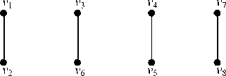
Fig 1: 1-dimensional hypercubes for the example of section 4
Table 1: The compact table for the partition from the example of section 4
5,9 1,5,9 5,7,9 1,5,7,9 2,5,9,12 5,6,7,9 1,5,8,9,11 2,5,9,10,12 3,5,6,7,9 4,5,6,7,9 3,5,8,9,10,11
|
4,6 2,4,5 4,6,12 1,6,9,11,12 2,4,5,8,12 2,5,7,10,11 2,5,8,11,12 3,6,7,9,10,11 |
0000 |
0000 |
0000 |
0000 |
0000 |
0100 |
0000 |
0000 |
0100 |
1111 |
0000 |
|
1110 |
1110 |
1110 |
1110 |
1111 |
1110 |
1110 |
1111 |
1110 |
1111 |
1110 |
|
|
0000 |
0000 |
0000 |
0000 |
1111 |
0100 |
0000 |
1111 |
0100 |
1111 |
0000 |
|
|
1110 |
1111 |
1110 |
1111 |
1111 |
1110 |
1111 |
1111 |
1110 |
1110 |
1111 |
|
|
1110 |
1110 |
1110 |
1110 |
1111 |
1110 |
1111 |
1111 |
1110 |
1111 |
1111 |
|
|
1110 |
1110 |
1110 |
1110 |
1111 |
1110 |
1111 |
1111 |
1110 |
1110 |
1111 |
|
|
1110 |
1110 |
1110 |
1110 |
1111 |
1110 |
1111 |
1111 |
1110 |
1110 |
1111 |
|
|
1110 |
1110 |
1110 |
1110 |
1110 |
1110 |
1111 |
1111 |
1110 |
1110 |
1111 |
|
|
Trivial |
000 |
001 |
000 |
001 |
010 |
011 |
100 |
101 |
011 |
110 |
100 |
|
Hypercube |
001 |
000 |
001 |
000 |
100 |
011 |
010 |
110 |
011 |
101 |
010 |
Then, 2 - dimensional hypercubes will be constructed. It is performed by adding two edges, viv j and vkvl such that w ij + w kl would be the minimum among all the selectable edges. All the variants of such adding are given in Table 3. The edge incident with vertex v 8 is not considered.
Table 4: The variants of the adding edges at the third step
|
Edges |
Σ w ij |
|
v 1 v 3 , v 2 v 6 , v 5 v 8 , v 4 v 7 |
25 |
|
v 1 v 7 , v 2 v 3 , v 5 v 6 , v 4 v 8 |
23 |
|
v 1 v 8 , v 2 v 7 , v 5 v 3 , v 4 v 6 |
27 |
|
v 1 v 6 , v 2 v 8 , v 5 v 7 , v 4 v 3 |
31 |
|
v 1 v 7 , v 2 v 8 , v 5 v 6 , v 4 v 3 |
24 |
|
v 1 v 3 , v 2 v 7 , v 5 v 8 , v 4 v 6 |
30 |
|
v 1 v 6 , v 2 v 3 , v 5 v 7 , v 4 v 8 |
31 |
|
v 1 v 8 , v 2 v 6 , v 5 v 3 , v 4 v 7 |
23 |
Having chosen the second variant, the final hypercube is constructed which is shown in Fig. 3.
Table 3: The variants of the adding edges at the second step
|
Edges |
w ij + w kl |
|
v 1 v 3 , v 2 v 6 |
18 |
|
v 1 v 6 , v 2 v 3 |
18 |
|
v 1 v 4 , v 2 v 5 |
6 |
|
v 1 v 5 , v 2 v 4 |
8 |
|
v 3 v 4 , v 6 v 5 |
14 |
|
v 3 v 5 , v 6 v 4 |
16 |
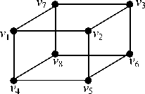
Fig. 3: The final constructed hypercube for the example of section 4
Having chosen the first variant, 2 - dimensional hypercube on the vertices v 1 , v 2 , v 5 and v 4 is obtained. Similarly, the second hypercube is constructed by vertices v 3 , v 6 , v 8 and v 7 . They are illustrated in Fig. 2.
v 1 v 2
v 3 v 6
Fig 2: 2-dimensional hypercubes for the example of section 4
To finish the process, four edges should be added to obtain the final 3 - dimensional hypercube. The variants of such adding are given in Table 4. One of the edges among them has infinity value of wi j . Therefore, the value of this edge is not considered in the resulting summation.
-
4.3 The Process of Encoding of the Hypercube
-
4.3.1 The basic encoding
-
4.3.2 The optimized encoding
The final process to encode the compact table is encoding of the constructed hypercube. The hypercube will be encoded according to the neighborhood relation represented by the graph in Fig. 3.
The method of the encoding is as follows. At first, the basic encoding is obtained by using Karnaugh map. The sequence of the vertices of the constructed hypercube is put in the Karnaugh map. The order of the vertices in the sequence is considered as Fig. 4a for the hypercube of Fig. 3. In this paper, this sequence is called the vector representation of the hypercube.
It is noticed that the placement of the Gray codes for Karnaugh map is performed according to the neighborhood relations of the constructed hypercube. It means that the concept of Karnaugh map is used and for some rank of the obtained hypercube some modifications are needed to reorder the map. It is necessary to keep the vicinity relations of the vertices. So, the basic encoding for the hypercube of Fig. 3 is represented in Fig. 4.b.
A supplementary improvement is made on the basic encoding if it is needed and it can be possible. It means with additional efforts, sometimes it is possible to achieve to the more efficient encoding. In case the current hypercube contains some virtual vertices, it would be done.
The final aim is obtaining a feasible version of the encoding vector which assigns the maximum possible 1’s for the codes of the virtual vertices. A feasible version is related to such permutations keeping the neighborhood relations. The operations of searching for the feasible version are similar to the hypercube construction.
Unfortunately, it is not possible always to find the optimal version, especially when the number of virtual vertices is more. But the basic encoding is still improved. The optimized encoding for the hypercube of Fig. 3 is shown in Fig. 4c. In the current example, the virtual vertex is only v 8. So the binary code “111” has been assigned for it which has the maximum possible 1's. For this example the obtained encoding is optimal.
-
a. I v1 I v2 I v5 I v4 I v8 I v6 I v3 I
-
b. I 0002 0012 0112 0102 1102 1112 1012
-
-
c. I 0012 0002 0102 0112 1112 1102 1002
-
4.4 To Obtain the Desired Superposition
-
4.4.1 The obtained superposition by using the trivial encoding method
Fig. 4: The encoding for the constructed hypercube. (a) The vector representation of the hypercube of Fig. 3 (b) The basic encoding (c) The optimized encoding
Finally, the distinct columns of the compact table will be encoded as v 1 – 001, v 2 – 000, v 3 – 100, v 4 – 011, v 5 – 010, v 6 – 110 and v 7 – 101, by using the hypercube encoding method. The repetitive columns of the compact table will be encoded according to their equivalent distinct encoded columns. In fact, the encoded columns will form the vector w .
The main object of the paper for this example was done. But, to obtain the solution of the task, the systems of functions y = ϕ (w, z2) and w = g (z1) should be constructed [8], [9]. For that, the functions connected with the blocks of the cover maps of Z1 and Z2 must be obtained. Then the DNFs of the functions connected with the blocks of π1 and π2 will be calculated. After a minimization with the well-known Espresso logic minimizer; the following systems representing the desired superposition y = ϕ (w, z2), w = g (z1) are obtained. For that, each of the calculated codes can be used. As mentioned before, for the comparison purpose; the desired superposition using each of them will be constructed.
The first system of superposition by using the trivial encoding method is:
.i 6
.o 4
.ilb w1 w2 w3 x1 x3 x4
.ob y1 y2 y3 y4
.p 13
-
-011110001
10--010001
010-0-0001
011---0100
1100--1111
010--11111
101--11111
101-0-1111
-
--01--1110
0--1--1110
10-1--1111
-
--0-0-1110
0---0-1110
.e
And the second system of superposition by using the trivial encoding method is:
.i 4
.o 3
.ilb x2 x5 x6 x7
.ob w1 w2 w3
.p 9
111-010
01-0100
0-11001
1-01010
00-0001
100-001
-
-00-010
-
4.4.2 The obtained superposition by using the hypercube encoding method
.e
Also, the first system of superposition by using the hypercube encoding method is:
.i 6
.o 4
.ilb w1 w2 w3 x1 x3 x4
.ob y1 y2 y3 y4
.p 10
-
- -01110001
-
- 10-010001
011---0100
1010--1111
0--1--1010
0---0-1110
-
- 0-1--1110
1-0--11111
1-0-0-1111
-
- 101--1111
.e
And the second system of superposition by using the hypercube encoding method is:
.i 4
.o 3
.ilb x2 x5 x6 x7
.ob w1 w2 w3
.p 8
01-0010
0-01001
11--100
-
100-010
-
--00010
10--001
-
-00-001
-
4.5 Discussion
.e
As it is seen from the obtained superpositions, the numbers of rows of the systems which have been constructed using the hypercube encoding method are less than their equivalent systems from trivial encoding method. This reduction is expected to be the more by increasing the number of the arguments or the DNFs of the original system. We also performed this method on the several examples and observed the similar results. In addition, the comparable work has been done on the problem of the state assignment of a finite state machine (FSM) to decrease the power of the implementing circuit [10]. Those results are confirmed our method as well.
-
V. Conclusion and Future Works
The ternary matrix cover approach is an efficient technique for the problem of decomposition of systems of Boolean functions. The encoding of the compact table columns has a direct influence on the quality and cost of the designing of the digital devices. So, its optimization will cause a significant improvement on the obtained solution. In this paper, we suggested the assembling of Boolean hypercube for the encoding of the columns. This encoding improves the desired superposition and reduces the size of PLA which is important in the practical applications.
Development and implementation of a software tool for investigation of the existing benchmarks is proposed. This will demonstrate the full impacts of the suggested method.
Acknowledgements
This work was done in the logical design laboratory at the united institute of informatics problems of the NAS of Belarus. The authors like to thank this laboratory by its support in providing the examples of the completely specified Boolean function to test.
References Improved Decomposition for a System of Completely Specified Boolean Functions
- Martinelli A. Advances in Functional Decomposition: Theory and Applications. Doctoral Dissertation, Royal Institute of Technology (KTH), Stockholm, Sweden, 2006
- Morawiecki P, Rawski M, Selvaraj H. Application of Functional Decomposition in Synthesis of Boolean Function Sets. In: Proceedings of the 19th International Conference on Systems Engineering (ICSENG), Aug. 2008, Las Vegas, USA, 350-355.
- Perkowski M A, Grygiel S. A Survey of Literature on Functional Decomposition, Version IV. Technical report, Department of Electrical Engineering, Portland State University, Portland, USA, 1995
- Zakrevskij A, Pottosin Yu V, Cheremisinova L. Optimization in Boolean Space. Tallinn, Estonia, TUT Press, 2009
- Hassoun S, Sasao T. Logic Synthesis and Verification. The Springer International Series in Engineering and Computer Science, Kluwer Academic Publishers, 2001.
- Rawski M. Input Variable Partitioning Method for Decomposition-Based Logic Synthesis targeted Heterogeneous FPGAs. International Journal of Electronics and Telecommunications, 2012, vol 58 (1), 15–20.
- Muthukumar V, Bignall R J, Selvaraj H. An efficient variable partitioning approach for functional decomposition of circuits. Journal of Systems Architecture, 2007, vol. 53, no. 1, 53-67.
- Pottosin Yu V, Shestakov E A. Tabular Methods for Decomposition of Systems of Completely Specified Boolean Functions. Byelorusskaya Nauka, Belarus, 2006 (in Russian)
- Taghavi Afshord, S, Pottosin, Yu V. On Decomposing Systems of Boolean Functions via Ternary Matrix Cover Approach. International Journal of Advanced Science and Technology, June 2013, Vol. 55, 33-42.
- Pottosin, Yu V, Pottosina, S A. State assignment of a finite state machine for a low power implementing circuit. In: Proceedings of the 8th International Conference, Nov. 2011, University of Zilina, Zilina, Slovak Republic, 113-116.
