Indoor Thermal Comfort Optimization by Field Synergy Principle for Air-Conditioning

Author: Shiuh Ming Chang, Hung Pin Chen
Journal: International Journal of Intelligent Systems and Applications(IJISA) @ijisa
Article in issue: 1 vol.3, 2011.
Free access
The principle of field synergy is to simulate the comfortableness of room in this study. The parameters U, V, W and input position of wind are calculated to simulate comfortableness of room. Temperature and velocity fields are simulated by COMSOL Multiphysics software. Comfortable degree is calculated by field synergy mean square root method in this research. The simulation result shows that field synergy angle decreases while comfortable degree increases. It is very obvious that the right input position of wind leads lower field synergy angle.
Temperature filed, velocity filed, simulation, comfortable degrees, field synergy principle
Short address: https://sciup.org/15010153
IDR: 15010153
Text of the scientific article Indoor Thermal Comfort Optimization by Field Synergy Principle for Air-Conditioning
Published Online February 2011 in MECS
In recent years, room comfort is important for people. Especially for office worker to maintain psychological or physiological well. Input wind position and temperature dominate major effect on comfort of room. In this study, we use COMSOL Multiphysics software to simulate thermal comfort of human in the specified room by field synergy principle and survey impact form parameters like input wind position, temperature and pressure for customer installation requirement.
Diversity of climatic conditions will affect the indoor climate in Taiwan, according to the research, one's life in 90% of the time in the broad interior space, therefore, whether the comfortable of indoor environment, it will significantly affect the human health, comfort, and working efficiency. As the global importance of sustainable development has begun to gradually, as the economy era for coming, people began to increasing of demand with comfort, health, and improve working efficiency for indoor environment quality, therefore, simulation and improve the indoor air will be imperative issues.
Humans spend 90% of their time indoors, thus comfortable indoor environments are part of the ideal living and working forms pursued by people. With the improvement of the life quality, there is a relative increase in the demand of comfortable habitation spaces. The indoor environmental quality is highly related to the thermal comfort, Due to the use of indoor air conditioning, and the goodness of indoor environmental quality, thermal indoor comfort would have great influence on work efficiency, human health, and impact on the environment.
For flow field and thermal comfort, ASHRAE, (1992)[1] and ISO(1995) (International Stan-darks Organization[2] proposed a standard according to human activity and his clothes as index PMV( Predicted Mean Vote ) PPD( Predicted percentage dissatisfied ) to decide. Hwang[3] proposed PMV , and discuss wind velocity effect on PMV to change velocity to improve environmental comfort. Experimental results show that analytical solution is more reliable than traditional solutions. Moreover, comfort is improved by different velocity of wind 。
1998 , Kuo[4-6] use boundary layer flow to enhance effect on heat transfer by field synergy principle to decrease the angle of velocity and temperature gradient field.
-
S. M. Chang [7] studied i ntegrated assessment for trapezoid and square types PEMFC bipolar plate by field synergy principle and found square type get uniform filling with lower field synergy angle.
Chang [8] using field synergy simulated t hermal comfort of passenger in the vehicle by field synergy principle and also pointed out the angle from temperature and velocity gradient we mean field synergy angle that can be the index of comfort of space of vehicle.
The freezer optimization of input fan location by field synergy principle also be researched by S. M. Chang[9]. MRT, submarine, CPU and aircraft optimization at different input wind positions still were studied by Chang[10-13] and found that lower angle of field synergy lead better comfort in the specified space he discussed.
In this research, we use COMSOL Multiphysics software and field synergy principle to analyze human thermal comfort of the specified room at different input wind position for different thermal load. For the field synergy angle result, we can compare optimal input and improve the magnitude of input wind velocity and position.
-
II. Basic Theory
-
A. Government Equation
For comfort of a specified vehicle, it is used global heat transfer mode a basic theory, including parameters setting of heat conduction, convection and radiation and definition of radiation to surface, or environment. Radiation to surface is used radiant method by diffuse reflection and shading.
Turbulence model is used k-ε turbulent model and incompressible flow to investigate flow field. Global heat conduction is written as :
V- (- KVT ) = Q - pC P u -V T (1)
where , Q > p > C P > V T represent heat source, > density, constant pressure capacity and gradient temperature, respectively.
Turbulent model and incompressible equation are as follows pu •Vu = V • [-PI + (n + nT)(Vu + (Vu)T)] + F
Where nT is turbulent viscosity, П is dynamic viscosity, P is pressure, I is logarithm of turbulent dissipation rate.
Boundary condition is considered pressure condition, non viscous stress condition :
(n + nT )(V u + (V u ) T ) n = 0
n*VK = 0,n-Vs = 0 ,P = P0
s = Cu0"5((3It2/2)(uо • uo))L5/Lt(5)
IT 2 is scale of turbulent , 、 u 0 is velocity in x
0.75
direction 、 Cu is constant
LT is scale length of turbulent when u = u0 , Heat flux at boundary condition is
-
- n • (- kVT + pcPuT ) = q 0 + h(T^ - T ) (6)
q 0 :
input heat flux ,
h : coefficient of heat convection
T inf : infinite temperature
T : temperature of flow field
-
B. filed synergy principle
By filed synergy principle, angle of filed synergy principle becomes smaller, it means velocity and temperature gradient of flow field become more parallel and more heat transfer rate в=U"VT1. UuT'':'”d;y+w■)
Average filed synergy angle is written as (7)
Ц edxdy m jj dxdy
L is mean square root of random 6 points in flow field and expressed as.
L =
в ^ + в 2 в 3 в 4 в 5 + в 6
If L is decreasing low, comfort of human is increasing.
-
III. Analysis of Simulation
A.Case1
First, the specified room dimension is 4m×4m×3m 、 output wind dimension is 0.5m×0.5m 、 input wind dimension is 1m×0.5m. There are six wind input positions and one wind output position ® as shown on Figure 1. Human body temperature is 36®, environmental temperature is 34 °C, wind input temperature is 20C > wind input velocity is 0.3~0.5m/s. In the present study, there is a man sitting inside the specified room to investigate these six wind input positions situations and. Human feels comfort at one of them by field synergy principle. COMSOL Multiphysics TM is used to describe PDEs in physics of this study.
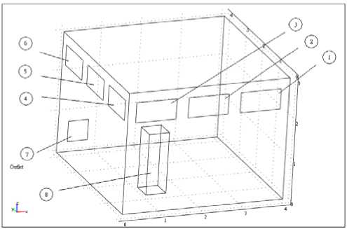
Figure 1 Different wind input positions( © ~ ® )and one wind output position ( ® ), Human is at position ®
-
A. Original design
In the original design, the mesh elements are 13613,analusis time of CPU is 535min. The room is like Figure 1.Six Wind input positions are considered. Figure 1 shows ® ~ ® the square type are wind input positions, wind output position is shown at ® . Human is at position ® . Environmental temperature of sun to the wall is 34 C,
wind input temperature is 20°C, velocity is 0.3m/s » By field synergy principle, the results will be compared for the six settings.
-
B. Different input wind position
Figures 2-7 are field synergy angle distribution at different wind input position 。 Figures 4 and 5 shows that field synergy angle range is 40~60, human feels comfortable at these two wind positions. At this time velocity and temperature gradient are more parallel. Figures 2 、 3 、 6 and 7show that field synergy angle range is 80-150. At this time velocity and temperature gradient are not parallel and wind is distributed to let human feel uncomfortable.
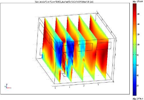
Figure 4 field synergy angle distribution (wind input position ® ) u=0.3, wind input temperature is 20 C , environment temperature is 34° C , human body temperature is 36 C .
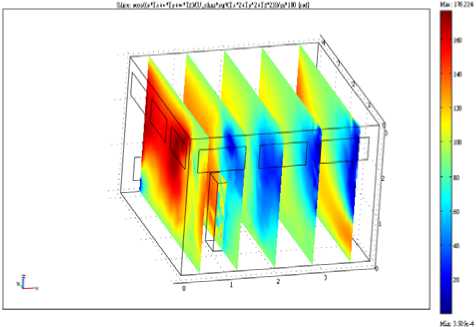
Figure 2 field synergy angle distribution (wind input position Ф ) u=0.3, wind input temperature is 20 C , environment temperature is 34 C , human body temperature is 36 C .
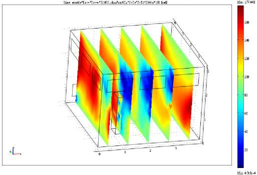
Figure 3 field synergy angle distribution (wind input position ® ) u=0.3, wind input temperature is 20 C , environment temperature is 34 C , human body temperature is 36 C
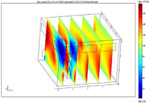
Figure 5 field synergy angle distribution (wind input position ® ) u=0.3, wind input temperature is 20 C , environment temperature is 34 C , human body temperature is 36 C .
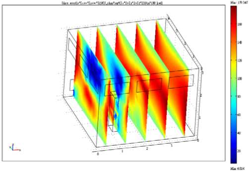
Figure 6 field synergy angle distribution (wind input position ® ) u=0.3, wind input temperature is 20 C , environment temperature is 34 C , human body temperature is 36 C
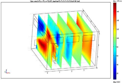
Figure 7 field synergy angle distribution (wind input position ® ) u=0.3, wind input temperature is 20° C , environment temperature is 34° C , human body temperature is 36° C
S«*Ae V*c.V*H
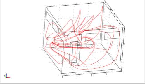
Figure 10 velocity distribution for wind position ®
-
C. Input wind velocity
Figures 8-13 show the velocity distribution for different wind input positions. Figures 10 and 11 are indicated that velocity is uniform through human position, the variation of temperature is smaller than that of figures 8,9,12 and 13 . Figures 8,9,12 and 13 show that velocity field is not smooth to cause human uncomfortable.
^те^м VMIdl
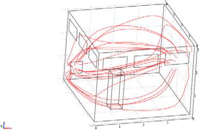
Figure 8 velocity distribution for wind position ©
Е*чв1ж Vebei*/
f
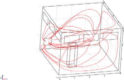
Figure 9 velocity distribution for wind position ®
TABLE I.
INDEX OF ROOM COMFORT SURVEY
|
index |
man |
Percentage of survey/% |
|
Humility |
5 |
23% |
|
temperature |
10 |
45% |
|
field synergy angle |
11 |
50% |
|
Air velocity |
8 |
36% |
|
Average room temperature |
10 |
45% |
|
Air condition position |
12 |
56% |
>.ы» v*u', '«a
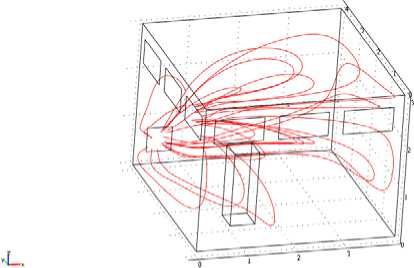
Figure 11 velocity distribution for wind position ®
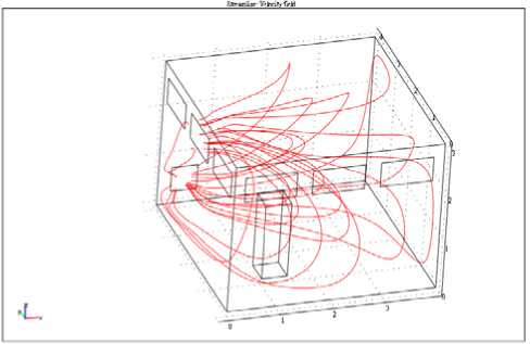
Figure 12 velocity distribution for wind position ®
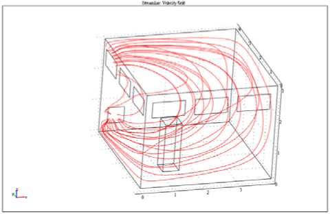
Figure 13 velocity distribution for wind position ®
-
D. Index of room comfort
The results of index of room comfort survey are shown as Table I (survey data from three air conditioning technicians one mechanical engineer four professors two doctors twelve students , choice could be repeat selected, total 22 men)
From Table I show field synergy angle is great index for room comfort. Figure 14 shows mean square root of field synergy angle for different wind input positions. The results shows that wind input positions 3 and 4, mean square root of field synergy angle is lower than that at the other wind input position. It is indicated that velocity and temperature gradient are consistent at these two wind positions. In the other word, mean square root of field synergy angle decrease, the index of comfort increases.
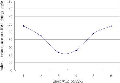
Fig 14 Mean square root of field synergy angle for different wind input positions
B.Case2
The truck dimension is 42m X 16m X 14m, output wind dimension is 0.05m X 0.05m, input wind dimension is 0.05m X 0.05m. There are six wind input positions and one wind output position as shown on Figure 15. Human body temperature is 36 C , environmental temperature is 32 °C, wind input temperature is 20 °C > wind input velocity is 0.5~1m/s.
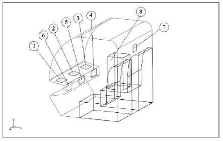
Fig 15 Different wind input positions( © ~ ® )and one wind output position ( ® ), Human is at position ®
Figures 16-21 are field synergy angle distribution at different wind input position. Figs 18 and 19 shows that field synergy angle range is 40~60, human feels comfortable at these two wind positions. At this time velocity and temperature gradient are more parallel. Fig 16 > 17 > 20 and 21show that field synergy angle range is 70-140. At this time velocity and temperature gradient are not parallel and wind is distributed to let human feel uncomfortable.
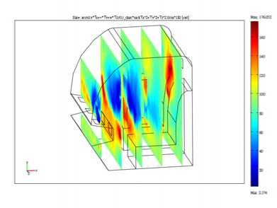
Fig 16 field synergy angle distribution (wind input position Ф ) u=1, wind input temperature is 20 ℃ , environment temperature is 32 ℃ , human body temperature is 36 ℃ .
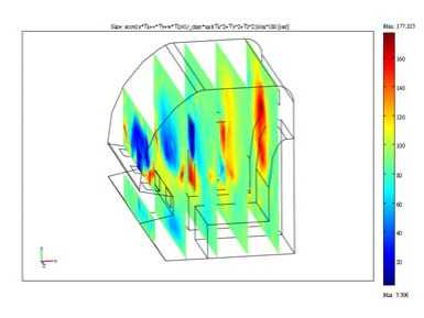
Fig 17 field synergy angle distribution (wind input position ® ) u=1, wind input temperature is 20 ℃ , environment temperature is 32 ℃ , human body temperature is 36 ℃
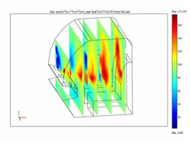
Fig 18 field synergy angle distribution (wind input position ® ) u=1, wind input temperature is 20 C , environment temperature is 32 C , human body temperature is 36 C .
wind input temperature is 20 C , environment temperature is 32 C , human body temperature is 36 C
Figures 22-27 show the velocity distribution for different wind input positions. Figs 24 and 25 are indicated that velocity is uniform through human position , variation of temperature is smaller than that of Figs 22, 23, 26 and 27. Figs 22,23,26 and 27 show that velocity field is not smooth to cause human uncomfortable.
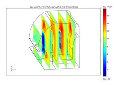
Fig 19 field synergy angle distribution (wind input position ® ) u=1, wind input temperature is 20 C , environment temperature is 32° C , human body temperature is 36 C .
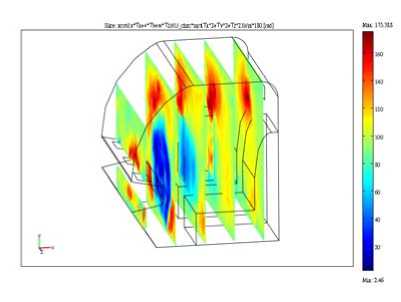
Fig 20 field synergy angle distribution (wind input position ® ) u=1, wind input temperature is 20 C , environment temperature is 32 C , human body temperature is 36 C
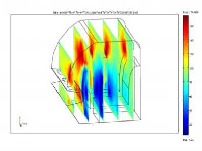
Fig 21 field synergy angle distribution (wind input position ® ) u=1,
Figure 28 shows mean square root of field synergy angle for different wind input positions. The results show that wind input positions 3 and 4, mean square root of field synergy angle is lower than that at the other wind input position. It is indicated that velocity and temperature gradient are consistent at these two wind positions. In the other word, mean square root of field synergy angle decrease, the index of comfort increases.
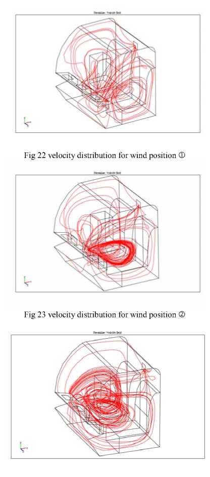
Fig 24 velocity distribution for wind position ®
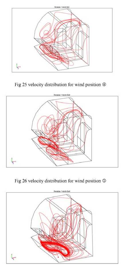
Fig 27 velocity distribution for wind position ®
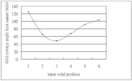
Fig 28 Mean square root of field synergy angle for different wind input positions
^.Results and Discussions
The present results show that wind input positions, field synergy angle and mean square root of field synergy angle are great influenced on comfort of specified room. The man position is with more relationship with wind input position. Field synergy angle is small, index of comfort in high and velocity of room is more uniform. By index of mean square root of field synergy angle, we can choose the better wind input position to decrease field synergy angle and get more parallel of velocity and temperature gradient. Therefore, index of mean square root of field synergy angle is the best index to thermal comfort of specified room. Future study is to simulate vascular flow and PEMFC bipolar plate with wavy shape by field synergy angle and mean square root of field synergy angle to get the optimization performance.
References Indoor Thermal Comfort Optimization by Field Synergy Principle for Air-Conditioning
- ASHRAE. Thermal environmental conditions for human occupan-cy [M]. Atlanta:ASHRAE, 1992
- ISO 7730. Moderate thermal environment - determination of the conditions of thermal comfort [S]. Geneva : International Standard Organization, 1994
- J. S. Hwang,“The Analysis and Application of the New Air-conditioning Comfort Index-PMV”, Master Degree,National Sun Yat-sen University,1994
- Z.Y. Guo, and C. M. Zhang,” Thermal drive in centrifugal fields-mixed convection in a vertical rotating cylinder,”. Int J Heat Mass Transfer, vol.35, pp.1635~1644, 1992
- Z. Y. Guo, D. Y. Li, and B. X. Wang, “A novel concept for convective heat transfer enhancement,” Int J Heat Mass Transfer, vol. 41, pp.2221~2225, 1998
- W. Q.Tao, Z. Y. Guo, and Wang B X, “Field synergy principle for enhancing convective heat transfer extension and numerical verification,” Int J Heat Mass Transfer, vol. 45,pp. 3849~3856, 2002
- S. M. Chang, J. H. Chang, and J. F. Lee, “Integrated Assessment for Trapezoid and Square Types PEMFC Bipolar Plate by Field Synergy Principle,” J. Pro. Mech. Eng., vol.3, no.1, pp.27-35, 2010
- S. M. Chang, J. H. Chang, and C. H. Chang,” Thermal Comfort of Passenger in the Vehicle by Field Synergy Principle,“J. Pro. Mech. Eng, vol.3, no.2, pp.8-13, 2010
- S. M. Chang, J. H. Chang, and M. H. Tsai,” The Freezer Optimization of Input Fan Location by Field Synergy Principle,“J. Pro. Mech. Eng.,vol.3, no.3, pp.29-33, 2010
- S. M. Chan, J. H. Chang and J. H. Huang, “Optimization Cooling Fan Position for CPU by Field Synergy Principle”, J. Pro. Mech. Eng, vol.3,nNo.3, pp.1-7, 2010 S. M. Chang, J. S. You, ” The Optimization Comfortness of Air Craft by Field Synergy Principle”, J. Pro. Mech. Eng , vol.3,nNo.4, pp.7-10,2010
- S. M. Chang, and G. L. Lee,” Comfort Design of Air Condition for MRT by Field Synergy Principle”, J. Pro. Mech. Eng, vol.3,no.4, pp.22-26,2010
- S. M. Chang, J. H. Chang, and M. S. Tsai,” The Submarine Air Condition Optimization by Field Synergy Principle”, J. Pro. Mech. Eng, vol.3, no.4, pp.44-49, 2010
- S. M. Chang, J. H. Chang, and H. P. Chen,” Truck Comfort of Air Condition by Field Synergy Principle”, 2010 International Conference on Logistics Engineering and Intelligent Transportation Systems (LEITS2010), pp. 186~189,2010
