Industrial Monitoring System with Real-time Alerts and Automated Protection Mechanisms

Author: Nabusha Alice, Asiimwe Julius, U. I. Bature, Mugisha Simon, Tusiime Meron
Journal: International Journal of Engineering and Manufacturing @ijem
Article in issue: 2 vol.15, 2025.
Free access
This work presents the design and prototyping of an Industrial Monitoring and Protection System aimed at enhancing safety and operational efficiency in industrial environments. The system integrates multiple sensors with a GSM module to monitor and respond to critical environmental parameters, such as ambient light levels, temperature, and smoke detection. A Light Dependent Resistor (LDR) is configured to detect excessive lighting levels, interfacing with a microcontroller to activate the GSM module and send alert messages when thresholds are exceeded. The temperature sensor continuously monitors ambient temperature, and upon detecting overheating, the microcontroller triggers the GSM module to notify operators. Similarly, a smoke sensor detects the presence of harmful smoke and initiates an alert through the GSM module for early fire hazard detection. These sensors are connected to the microcontroller via analog and digital input pins, with their outputs processed to enable condition-based responses. A relay switch, controlled by the microcontroller, automatically disconnects connected loads when safety thresholds are breached, preventing equipment damage and ensuring personnel safety. Real-time sensor readings and system status are displayed on an OLED screen, providing operators with comprehensive, up-to-date information on the monitored environment. The system dynamically responds to environmental conditions by triggering alerts and actions based on customizable safety thresholds for light intensity, temperature, and smoke levels. This integrated architecture ensures seamless communication between sensors, the microcontroller, and the GSM module, delivering real-time monitoring, automated protective mechanisms, and early warning capabilities. The proposed system demonstrates the feasibility of affordable and scalable solutions for industrial safety, offering immediate responses to hazardous conditions while minimizing downtime. Furthermore, its adaptable design allows for customization across different industrial environments, making it suitable for a wide range of applications.
Industrial Monitoring, Protection System, Sensors, Potential Hazard, Safety
Short address: https://sciup.org/15019703
IDR: 15019703 | DOI: 10.5815/ijem.2025.02.05
Text of the scientific article Industrial Monitoring System with Real-time Alerts and Automated Protection Mechanisms
Industries often face operational challenges such as equipment failure, fire outbreaks, and environmental hazards, which can significantly affect productivity, safety, and costs. These issues are particularly prevalent in environments with high-power equipment and hazardous conditions, where continuous monitoring is crucial to ensure safe operations. However, many industrial plants still rely on manual supervision and conventional alarm systems, which can fail to provide timely or adequate responses to emerging dangers [1]. This research aims to address this gap by developing an automated, real-time Industrial Monitoring and Protection System. The system is designed to enhance safety by integrating multiple sensors for detecting excessive ambient lighting, overheating, and fire risks. Using a Light Dependent Resistor (LDR) to monitor light levels, a temperature sensor to detect high temperatures, and a smoke sensor to identify fire hazards, the system triggers immediate alerts through a GSM module when any of these parameters exceed predefined safety thresholds. Additionally, a relay switch is incorporated to disconnect critical equipment automatically, preventing damage. This project focuses on providing an affordable, scalable solution that improves industrial safety, reduces downtime, and protects both personnel and equipment. By leveraging advanced sensor technology and communication systems, this system offers a reliable approach to mitigating risks and enhancing operational efficiency in industrial environments.
This paper is organized as follows: Section 2 provides a review of related works, highlighting current approaches to industrial monitoring and safety systems. Section 3 details the design and prototyping of the Industrial Monitoring and Protection System, including the selection of sensors, communication modules, and the overall system architecture. Section 4 presents the integration and testing of the proposed system, demonstrating the simulations of electrical circuits with schematic diagrams, integration of various components and testing after being soldered on the veroboard. Section 5 discusses the results obtained and challenges faced during the design and prototyping phases, along with proposed solutions and project’s contributions. Finally, Section 6 concludes the paper, summarizing the findings and suggesting directions for future research and development in industrial safety systems.
2. Related Works
Industrial monitoring and protection systems are essential components of modern industrial operations, playing a critical role in ensuring safety, minimizing downtime, and protecting equipment and personnel. Over the years, numerous technologies have been developed and employed to detect and respond to hazardous conditions such as excessive heat, fire, gas leaks, and equipment malfunction. This literature review discusses relevant studies, technologies, and systems related to industrial monitoring, protection mechanisms, and their applications.
Industrial monitoring systems are designed to continuously observe environmental and operational parameters such as temperature, humidity, light intensity, and gas levels, and to provide early warning or automatic intervention when hazardous conditions arise. According to M. Javaid et al. [2], the use of sensors for real-time monitoring has become commonplace in modern industries, reducing the risks of accidents and allowing for timely preventive measures. Sensors such as temperature detectors, smoke sensors, and light sensors are often employed to detect potential hazards that could lead to equipment damage or safety issues. The study by B. D. Majumder et al. [3] highlights the importance of integrating various sensors into a single system to monitor multiple parameters at once. The authors note that combining data from different sensors allows for a more comprehensive view of potential vulnerabilities, improving overall safety. For instance, a rise in temperature combined with the detection of smoke may indicate an imminent fire hazard, requiring immediate action [4]. This approach forms the basis for multi-parameter monitoring, which is highly effective in industrial settings.
Sensor technology has advanced significantly in recent years and applied in various settings [5, 6, 7], enabling more precise detection of hazards [2, 8]. In the context of this project, three primary sensors are employed: the Light Dependent Resistor (LDR), temperature sensors, and smoke detectors. LDRs are widely used for monitoring light intensity in industrial environments [9]. LDRs are cost-effective and reliable for detecting ambient light changes, making them suitable for environments where light levels need to be controlled or monitored, such as in warehouses and manufacturing facilities. The research emphasizes that sudden increases in light levels could indicate electrical failures or fires, especially in areas with critical lighting systems [10]. Temperature sensors, such as the LM35 and DS18B20, are crucial for detecting overheating, which is a common cause of industrial failures and accidents [11]. Smoke sensors, particularly the MQ2, are commonly used in fire detection systems. According to G. Gathiya et al. [12], smoke sensors are vital in identifying fire hazards before flames become visible. Their research demonstrated that early smoke detection could significantly reduce fire damage at home and industrial settings by enabling quick responses such as activating alarms, sending alerts. The MQ2 sensor, in particular, is known for its sensitivity to smoke, methane, and other gases, making it a versatile tool for industrial safety.
The use of GSM technology for sending alerts via SMS has transformed how industrial safety systems operate. With the introduction of mobile communication in monitoring systems, real-time alerts can be sent to operators or management, even if they are not on-site [13]. The study by D. Patra et al. [14] demonstrates the effectiveness of GSM modules in transmitting critical information about system malfunctions or environmental hazards. The authors present a system for remotely controlling and monitoring a furnace using GSM technology and dual microcontroller units. The design allows users to send authenticated commands via mobile devices, which the system processes to execute actions or retrieve equipment status.
Relays play a crucial role in industrial systems by disconnecting power or machinery when dangerous conditions are detected. According to M. Pilon et al. [15], the inclusion of relays in protection systems helps mitigate risks associated with high temperatures or electrical overloads. When integrated with sensors and a central control unit, relays can automatically switch off machinery to prevent damage, reducing repair costs and enhancing worker safety. The use of relays in this project allows for the automatic disconnection of industrial loads when any of the monitored conditions (light, temperature, or smoke) exceeds the preset threshold. OLED displays have gained popularity in industrial monitoring systems due to their clarity, low power consumption, and ability to display critical data in realtime. Research by A. A. Jaber et al. [16] suggests that OLED screens provide a user-friendly interface for displaying real-time sensor readings, allowing operators to monitor various parameters at a glance. The use of OLED displays in the proposed system ensures that data from the sensors is easily accessible and interpretable, which improves decisionmaking in critical situations. The integration of sensors, GSM modules, relays, and OLED displays into a single system forms a comprehensive industrial monitoring and protection system. A. A. Jaber et al. [16] discusses the advantages of combining multiple technologies into one cohesive system, noting that integrated systems can automatically respond to hazards, provide real-time updates, and ensure a holistic approach to industrial environment safety. The study points out that such systems are particularly useful in industries where constant monitoring is required, and any delay in response could result in significant damage or loss, as similarly captured in [1. 2, 9, 11, 14].
While existing studies have explored individual components of monitoring systems, such as temperature or smoke sensors [2, 12], GSM alerts [13], or relays [15], this work uniquely integrates these technologies into a comprehensive solution tailored for industrial applications. This holistic approach enhances detection accuracy, response time, and system reliability, addressing critical gaps identified in the literature. Although further evaluation under diverse industrial conditions is necessary to ensure broader applicability, future enhancements such as IoT integration and advanced sensor fusion techniques are planned to improve functionality.
3. Methodology
This section describes the systematic approach used to create the suggested system. It lists and explains the different tools and applications that were utilised, along with the steps that were followed to create the prototype.
-
3.1 Conceptual Frame Work of the Proposed System
-
3.2 . Components of the System
The project involves implementing various components; Arduino Uno, MQ2 gas sensor, OLED displays, Light Dependent Resistor (LDR), Temperature Sensor (DS18B20), Buzzer, SIM800L GSM cellular chip, Buck converter (LM2596 DC-DC 3A buck), Battery shield and Relay module.
-
3.2.1. Arduino Uno Board
This section presents the various equipment and components used to develop the project structure, as illustrated in the block diagram of Fig. 1. This Figure provides a high-level overview of how the system components interact to monitor, alert, and protect the industrial environment. In essence, the system continuously monitors critical environmental parameters, automatically alerts the operators, and takes protective actions.
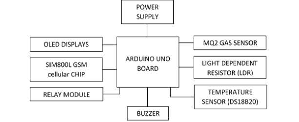
Fig. 1. Block diagram of the system
The Arduino Uno, an upgrade to the Arduino Duemilanove, is a microcontroller board featuring a removable ATmega328 AVR microcontroller in a dual-inline-package (DIP) design, as depicted in Fig. 2. It offers 20 digital input/output pins, with 6 configurable as PWM outputs and another 6 as analog inputs. Additional features include a 16 MHz resonator, a USB port, a reset button, a power jack, and an ICSP header. Renowned for its beginner-friendly design, the Arduino Uno serves as an excellent entry point for learning and experimenting with electronics and programming.
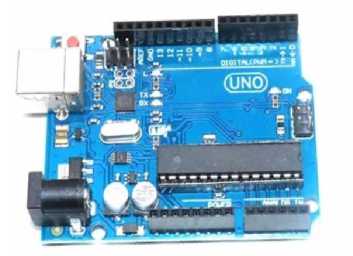
Fig. 2. The board of Arduino Uno
The Arduino Uno has a microcontroller which is used to store the codes and does the execution of the code. All the sensors and displays were connected to the Arduino Uno, part of the connection is shown in Fig. 3.
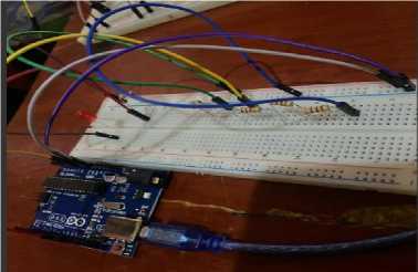
Fig. 3. Arduino Board Connections
Furthermore, on this Arduino is where I connected all the sensors by putting the analogue sensors on Analogue pins and the other sensors or other pins of the Arduino.
-
3.2.2. Smoke Sensor (MQ-2)
-
3.2.2.1. Calibration of the Sensor
The MQ2 gas sensor operates with a 5V DC power supply and has a power consumption of approximately 800mW. It is capable of detecting a variety of gases, including LPG, smoke, alcohol, propane, hydrogen, methane, and carbon monoxide, with detection concentrations ranging from 200 ppm to 10,000 ppm, as illustrated in Fig. 4.
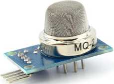
Fig. 4. Smoke Sensor
This sensor was selected for its key benefits, such as heater-driven sensing capabilities. It is enclosed within two layers of fine stainless steel mesh, referred to as an "anti-explosion network," which prevents the heater element inside from triggering explosions while detecting flammable gases. Additionally, the mesh serves to shield the sensor from damage and filters out suspended particles, allowing only gaseous substances to enter the sensing chamber. However, since the MQ2 is heater-driven, prolonged storage may lead to sensor calibration drift, necessitating recalibration before use.
When used after prolonged storage (one month or longer), the MQ2 gas sensor requires a full warm-up period of 24 to 48 hours to achieve optimal accuracy. In cases where the sensor has been recently operated, the warm-up time is significantly reduced to 5 to 10 minutes. During this process, the sensor's readings tend to start high and gradually decrease until reaching a stable state. This behavior ensures reliable and precise gas detection after sufficient preparation. The calibration setup of the sensor and the Arduino Uno board is shown in Fig. 5.
In the initial experiment, we measured the analog output from the gas sensor to evaluate the concentration of gas and check if it remained within acceptable limits. To set up the hardware, connect the VCC pin of the sensor module to the 5V pin on the Arduino and the GND pin to the Arduino's Ground. Next, link the module's A0 output pin to the Analog pin A0 on the Arduino.
To calibrate the sensor threshold, place it near the targeted gas or smoke source and adjust the potentiometer on the module. Turn the potentiometer until the Status LED lights up, then rotate it slightly in the opposite direction until the LED turns off. This calibration helps establish a precise threshold for detecting the presence of the specific gas.
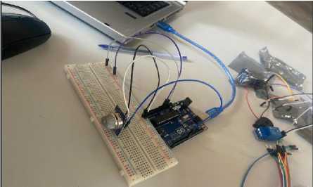
Fig. 5. Smoke Sensor Calibration
Furthermore, the sensor was programmed to measure the smoke particles and if there is any smoke, the Arduino should trigger the relay pin 7 to turn off the load and also send an SMS to the maintenance department.
-
3.2.3. OLED Display
OLED displays, commonly available in sizes like 128×64 and 128×32, come in various colors such as white, blue, or dual-color. They are equipped with either I2C or SPI interfaces for communication. Central to their functionality is the SSD1306 controller, which efficiently manages RAM buffering, minimizing the workload on the microcontroller. These displays offer compactness and versatility, making them ideal for embedded systems and compact interfaces. The OLED used in this project, as shown in Fig. 6, reflects these characteristics, contributing to efficient visualization and data presentation.
-
3.2.4. Light Dependent Resistor (LDR)
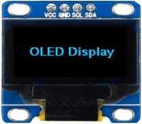
Fig. 6. OLED display
An OLED display is distinct from a character LCD display in that it does not need a backlight, as it generates its own light through organic compounds. This leads to enhanced contrast, a wider viewing angle, and deeper black levels. Additionally, the lack of a backlight significantly reduces power consumption, typically consuming around 20mA, though this can vary depending on how much of the screen is illuminated. These features make OLED displays energyefficient and capable of producing vibrant, sharp visuals. In this project, the OLED display was used to showcase various monitored parameters, such as data from the smoke sensor, light-dependent resistor (LDR), and digital temperature sensor, as illustrated in Fig. 7.
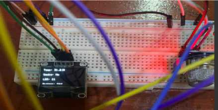
Fig. 7. OLED display Connection
The system utilizes a Light Dependent Resistor (LDR) to detect light intensity. The LDR, when connected to a 5V supply, generates an analog voltage that varies with light intensity. This voltage is then converted into a digital value by the Arduino's built-in Analog-to-Digital Converter (ADC), producing a range of 0 to 1023. As the light intensity increases, the digital value rises, typically falling between 800 and 1023 under bright conditions. This enables the system to measure and respond to light changes accurately.
The LDR is connected to the Arduino's analog input pin (A0) using a voltage divider configuration. In this setup, one leg of the LDR is connected to VCC (5V), while the other leg is linked to analog pin A0 on the Arduino. A 100K resistor is also connected to the same leg of the LDR and grounded, forming the voltage divider. Additionally, the LDR is also connected to pin A1 of the Arduino for measuring light intensity. When light levels increase, the system triggers a relay to disconnect the load and sends an alert to the maintenance department. The connection diagram is shown in Fig. 8.
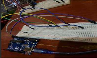
Fig. 8. LDR sensor Connection
-
3.2.5. Temperature Sensor (DS18B20)
-
3.2.6. Buzzer
The DS18B20 is a 1-Wire temperature sensor that requires only a single digital pin for communication with a microcontroller. It comes in two form factors: a standard TO-92 package or a waterproof probe for more demanding environments. The sensor has a wide temperature range of -55°C to +125°C and offers high accuracy with a tolerance of ±0.5°C. Its resolution can be set from 9 to 12 bits, with the default being 12 bits (0.0625°C precision). Powered by 3V to 5.5V and drawing only 1mA during active conversions, the DS18B20 is energy-efficient and does not require external components, making it ideal for various temperature monitoring applications. The sensor used in this work is shown in Fig. 9.
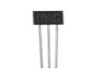
Fig. 9. Temperature Sensor (DS18B20)
The wiring process is simple. Start by connecting the VDD pin of the DS18B20 sensor to the 5V pin on the Arduino and the GND pin to the ground. Next, connect the DQ (data) pin to digital pin 2 on the Arduino. To ensure stable communication, a 4.7kΩ pull-up resistor should be placed between the DQ and the 5V power pins (note that the internal pull-ups on the Arduino will not be sufficient for this connection). It's important to connect the sensor properly to prevent overheating or potential damage.
Furthermore, it was programmed if the temperatures excide 38 degrees Celsius, the relay is triggered to turn off the load and also send an alert via the GSM module.
A buzzer is a device that transmits auditory signals and may comprise piezoelectric, electromechanical, electromagnetic, magnetic, or mechanical. A piezoelectric buzzer is typically powered by an oscillating electronic circuit or another audio signal source. It emits a sound, such as a click or beep, which may indicate actions like a button press. Buzzers are available in various types, with differences in their sound levels. In this system, a buzzer is connected to a microcontroller to alert users with alarms triggered by conditions such as high temperature, abnormal light intensity, or smoke detection. An example of the buzzer used in this system is shown in Fig, 10.
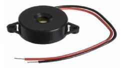
Fig. 10. Buzzer
-
3.2.7. SIM800L GSM Module
The SIM800L GSM module, featuring a SIM800L GSM cellular chip by Simcom, operates within a voltage range of 3.4V to 4.4V, making it ideal for direct connection to LiPo batteries. This feature makes it highly suitable for projects with space constraints. The necessary data pins for communication with a microcontroller via UART are exposed on 0.1" pitch headers. The module supports baud rates from 1200 bps to 115200 bps, with automatic baud rate detection. The specific module used in this project is shown in Fig. 11.
-
3.2.8. Buck Convertor
Since the GSM voltage is between 3.7V-4.4V, there must be need to use a buck convertor that converts from 5V to 4.16V. The bulk converter (LM2596 DC-DC 3A Buck) used in this work is shown in Fig. 12.
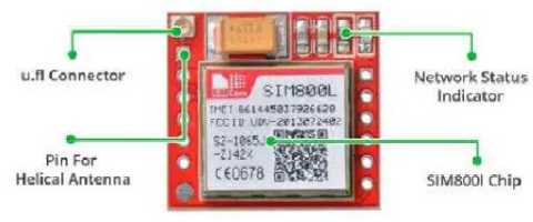
Fig. 11. SIM800L
The SIM800L module features an LED indicator that signals the status of the cellular network. The LED blinks at varying rates to represent different operational states. A crucial factor in ensuring the proper functionality of the SIM800L is providing adequate power. The module can be power-intensive, particularly during data transmissions. While it typically doesn’t draw the maximum power, it may require up to 2A during transmission bursts. In certain modes, such as phone calls, it consumes about 216mA, and during network transmissions, it draws approximately 80mA.
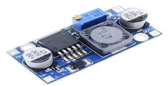
Fig. 12. LM2596 DC-DC 3A Buck
However, there should be a battery for supplying the GSM. The battery should be able to supply a current of more than 2A. The battery shield with a buck booster which gives 5V with 3A and 3.3V with 1A is used with a rechargeable battery of 3.7V. The battery shield and battery used are shown in Fig. 13.
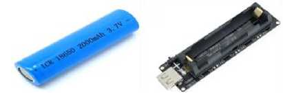
Fig. 13. Shield and Lithium Rechargeable Battery
3.2.9. Relay Module
4. Integration and Testing of the Proposed System
In this project, the Arduino was used for regulation. However, since the Arduino operates at 5 volts, it cannot directly control appliances. Additionally, in this work, the load was connected to the NC (Normally Closed) terminal, allowing the load to remain on during normal conditions and turn off when the monitored conditions are triggered. The Relay and the connection pattern used in this work is shown in Fig. 14. Also, the completed prototype connection of the relay and a load (Lamp) is shown in Fig. 15.
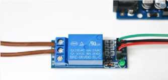
Fig. 14. Relay module overview
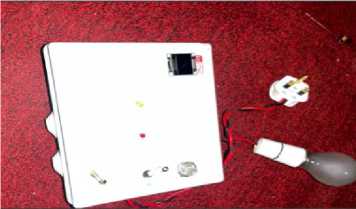
Fig. 15. Arduino with the relay module and load connected
Proteus software is the software used to make simulations of electrical circuits with schematic diagrams. It involves uploading libraries for different desired components and some components have there working codes. Below is the schematic diagram of the project uploaded from Proteus software and tested as shown in Fig. 16.
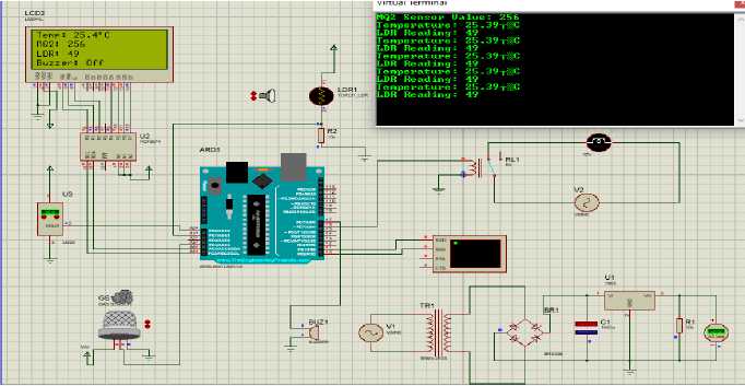
Fig. 16. Simulation Diagram of the Proposed System using Proteus 8.0 Software
Following the design of the system, the various components were tested individually to verify that each one worked correctly before they were integrated into the system. The components were first assembled and connected on a breadboard to ensure that the intended system would reliably serve its purpose. The connected components are shown in Fig. 17a.
After performing tests on the components using a breadboard, they were meticulously transferred and soldered onto the veroboard to create a stable and durable setup. This process ensured secure connections and was executed with care to avoid short circuits and loose connections, which are essential for the effective operation of the Battery Management System. The completed casing of the system is shown in Fig. 17b.
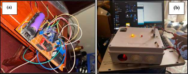
Fig. 17. The Proposed system: (a) Components Connection on Vero Board. (b) Casing of the System.
5. Result and Discussion
The simulation results were obtained using Proteus 8.0 software, which was key in linking the components’ design numbers. This software helped verify the design's effectiveness by ensuring proper interconnection of components, allowing for a detailed simulation before physical implementation. This approach reduced errors and ensured the design's reliability. The integrated components after soldering is shown in Fig. 18.
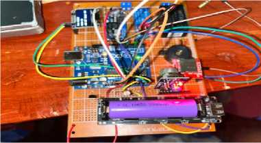
Fig. 18. Project Overview
-
5.1. LDR Sensor Result
-
5.2. Temperature Sensor Results
-
5.3. Challenges Encountered and Solutions
The LDR was employed to assess the intensity of light within the industrial environment. The testing procedure began with the LDR sensor, which measured light intensity by detecting changes in voltage levels. These values were displayed on the OLED screen for real-time monitoring, as illustrated in Fig. 19. To evaluate the effectiveness of the sensor, we configured the LDR to trigger a relay if the voltage surpassed a predefined threshold, indicating excessive light intensity. Additionally, the system was programmed to send an SMS alert with the message “Too much light,” providing real-time notifications of potentially hazardous conditions. During testing, the environment’s temperature was recorded at 31.21°C, and no smoke was detected, confirming that no fire hazard was present. The LDR sensor reading was at a level of 21, which is within the normal range under typical lighting conditions. However, when exposed to
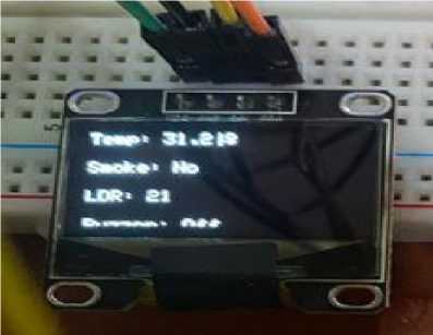
Fig. 19. Result Displayed on OLED screen increased lighting conditions, the sensor responded accordingly by activating the relay and sending the SMS alert. The results from the LDR testing demonstrate the potential of the integrated system for real-time light intensity monitoring and alerting in industrial settings. The ability to automatically trigger interventions, such as turning off equipment or notifying operators, underscores the practical application of this system in preventing accidents related to electrical faults or fire hazards caused by abnormal lighting levels.
The temperature sensor was tested by monitoring the temperature values displayed on the OLED screen, with the system set to trigger a relay and disconnect the load if the temperature exceeded a predefined threshold of 45°C. Fig. 20 shows the temperature variations, such as from 26.81°C to 26.75°C, illustrating the sensor's precision in detecting even the slightest changes in temperature. When the threshold was exceeded, the relay successfully turned off the load, and an SMS alert was sent to notify the user, demonstrating the system’s ability to monitor temperature in real time and automatically intervene to prevent overheating. This result not only validates the system’s practical application for industrial safety but also contributes to the theoretical understanding of temperature monitoring in integrated safety systems. Practically, it offers a reliable and cost-effective solution for managing overheating risks, crucial for preventing equipment damage and ensuring safety in industrial settings.
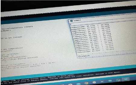
Fig. 20. Temperature sensor results
During prototyping, challenges included selecting compatible components, ensuring system stability, and testing in real-world conditions. Power management, GSM module connectivity, and sensor calibration were also key issues. Time constraints and a bulky prototype size required prioritization of features and design adjustments. These challenges were addressed through iterative testing, efficient power solutions, and design refinements to improve overall performance and adaptability.
5.4. Project’s Contribution
6. Conclusion
The main contribution of this work is the design and prototyping of an Industrial Monitoring and Protection System that integrates multiple sensors for real-time monitoring and automatic protection. The system addresses key safety concerns such as excessive ambient lighting, overheating, and fire hazards, providing a scalable and affordable solution for improving industrial safety and operational efficiency. The experimental part demonstrates the system’s functionality, including the integration of LDR, temperature, and smoke sensors with a GSM module for immediate alerts, and a relay switch for automatic equipment shutdown. This contribution offers a reliable approach to mitigating risks and minimizing downtime in industrial environments.
Implementing the Industrial Monitoring and Protection System in a real-world production environment involves adapting it to specific industrial needs, integrating sensors and communication modules, and ensuring seamless interaction with existing machinery. Key steps include system installation, calibration, testing, and staff training. The system must be scalable, maintainable, and compliant with safety standards. Future improvements could include data analytics, IoT integration, and predictive maintenance to enhance performance, reduce downtime, and ensure long-term reliability.
The Industrial Monitoring and Protection System developed in this project demonstrates a significant advancement in ensuring real-time protection for industrial environments by effectively detecting critical environmental changes such as temperature, light intensity, and smoke. By integrating sensors with automated control systems, including relay activation and GSM alerts, the system enables rapid responses to potential hazards, thereby enhancing both safety and operational efficiency while minimizing downtime caused by environmental issues. This system's use of low-cost, widely available components like the Arduino microcontroller, GSM module, and various sensors underscores its practical feasibility and accessibility for industrial applications. The broader implications of this work are notable in both theoretical and practical contexts. The system contributes to the field by providing a cost-effective solution for environmental monitoring and automated hazard detection in industrial settings, where real-time intervention can significantly reduce risks and costs associated with equipment damage and safety hazards. The integration of multiple sensors into a unified system also advances the theoretical understanding of how such systems can be optimized for industrial safety, improving detection accuracy and response time. On a practical level, this system could influence industry practices by offering a scalable and reliable approach to automated environmental monitoring. As industries continue to seek ways to enhance safety while reducing operational costs, this system’s integration of sensors, communication technologies, and automated controls offers a tangible solution. Future developments could focus on expanding its capabilities through advanced sensor fusion techniques, IoT-based features, and improved scalability, leading to enhanced functionality, predictive maintenance, and remote monitoring.
Acknowledgment
The authors express their sincere gratitude to the Faculty of Engineering, Technology, Applied Design, and Fine Art (FETADFA) at Kabale University for providing the necessary facilities, a conducive learning environment, and the support that ensured the successful completion of this project.
