Inpainting of structural reconstruction of monuments using singular value decomposition refinement of patches

Author: Anupama S. Awati, Meenakshi. R. Patil
Journal: International Journal of Image, Graphics and Signal Processing @ijigsp
Article in issue: 5 vol.11, 2019.
Free access
Image Inpainting of ruined historic monuments and heritage sites can help in visualizing how these may have existed in the past. An inpainted image of a monument can serve as a tool for physical reconstruction purpose. The purpose of the proposed method is to fill cracks and gaps of selected damaged regions in heritage monuments by exploiting the statistical properties of foreground and background along with the spatial location of the damage in the image of the monuments. The patch based image inpainting algorithm is improved by segmenting the image using K means clustering to search the candidate patches in relevant source region only. Segmentation improves patch searching in terms of both quality and time. The priority of the patch to fill is decided based on the standard deviation of the patch around destination pixel. Kn similar patches are selected from the source region based on minimum value of sum squared distance. The selected patches are refined using an efficient patch refinement scheme using higher order singular value decomposition to capture underlying pattern among the candidate source patches. The threshold for refinement is selected by using minimum and maximum value of standard deviation of the target patch. This eliminates random variation and unwanted artifacts. Experimental results carried on a large number of natural images and comparisons with well-known existing methods demonstrate the efficacy and superiority of the proposed method.
Patch Inpainting, segmentation using K means clustering, Singular Value Decomposition Refinement of Patches, Reconstruction of Monuments
Short address: https://sciup.org/15016054
IDR: 15016054 | DOI: 10.5815/ijigsp.2019.05.05
Text of the scientific article Inpainting of structural reconstruction of monuments using singular value decomposition refinement of patches
Published Online May 2019 in MECS DOI: 10.5815/ijigsp.2019.05.05
Historic monuments and heritage sites represent great achievements in art and architecture. It is important to preserve them so that we can continue to enjoy them and future generations can learn from them. These are important sources of knowledge across the world which introduces us to our cultural history, depicting the evolution of humankind. They are a valuable asset that signify the culture and civilization of the past, and portrays masterpieces that symbolize the human potential. Such places are important as they can contribute significantly to nation’s economic growth because they are excellent tourist attractions. It is for this reason many government organizations have been taking keen interest towards safeguarding and preserving the heritage sites.. However, the renovation may not only pose danger to the undamaged monuments, but may also fail to mimic the skillful historic work. Alternatively, it would be interesting to digitally reconstruct the heritage sites since such a process avoids physical contact to the monuments. Image Inpainting of ruined historic monuments and heritage sites can help in visualizing how these may have existed in the past. An inpainted image of a monument can serve as a tool for physical reconstruction purpose.
Image inpainting technique is the process of filling unknown or missing region with the information from known region of the same image so that the inpainted image becomes visually pleasant. Two major applications of image inpainting techniques are scratch removal and object removal. The methods are classified as diffusionbased methods and patch based methods. In diffusionbased methods information is smoothly propagated inward the missing region from its boundary. These methods use partial differential equation (PDE) to propagate linear structures along the isophote direction. PDE based methods are efficient for mostly thin target region (e.g., scratch) surrounded by smooth region but create a blurring effect due to the smoothing term. The [2] basic idea of exemplar- or patch-based methods is to fill the target region by copying the well-matched source patches (i.e., candidate patches from the source region) to the corresponding target locations. In [3], the exemplar based technique is improved by using adaptive size of window; the size of window is selected based on patch sparsity. Three similar patches are selected and difference between them is calculated. If the difference is less than a threshold, it means that the location of these patches is nearly the same place, so it selects the most similar patch to inpaint. If one of the differences is larger than a threshold, then it expands the patch size and selects the correct patch. In [4] algorithm relies on the use of structure tensors to define the filling order priority and template matching. K-nearest neighbor algorithm is used for template matching. Paper [5] suggested improvement in the fill-in order based on a combination of priority terms, previously defined by Criminisi, which encourages the early synthesis of linear structures and modification in distance calculation for selecting a similar patch by using Hellinger distance. The structure tensor used into the priority formula increases the structural information and reduces the error matching rate. The time required for a matching patch is greatly reduced by converting the global search matching algorithm into local search. Eigen values of the structure tensor is used in the matching criterion to improve the matching accuracy [6]. Paper [7] suggested an improved method in which image inpainting is performed accurately by modified distance function using image gradient as a similarity metric. Author of paper [8] proposed an exemplar-based image inpainting algorithm, which uses perceptual-fidelity aware mean squared error for evaluating the inpainted images. [9] Suggests a new equation for calculation of priority term by considering curvature information and chooses similar patches based on gradient and color information between the known pixels in the target patch. In [10] the inpainting problem is formulated using an exemplar based method with offset map. A energy function is added to a data term which is minimized to improve the accuracy of the algorithm. A novel approach for image inpainting is proposed in [11] to solve the inpainting problem using a metric label. A simulated annealing algorithm is used to solve this metric labeling problem to generate images with better visual quality. In paper [12] a method for image inpainting using low rank approximation, which avoids the time-consuming iterative shrinkage is proposed. The similar patches of a corrupted image are identified and reshaped as vectors, then a patch matrix can be constructed by collecting these similar patchvectors. This matrix is of low rank, a low rank approximation is used to estimate the patch. [13] Proposes a fast MRF-based hole filling method which utilizes an energy minimization problem with loopy belief propagation (LBP). [14] This paper addresses the image synthesis task, focusing on two specific families of images—handwritten digits and face images. The proposed algorithm uses pyramidal, up scaling and refining the estimated image several times. [15] suggested a structure-guided framework for exemplarbased image inpainting to maintain the neighborhood consistence and structure coherence of an inpainted region. [16] proposed an algorithm that is capable of reproducing the underlying textural details using a nonlocal texture measure and also smoothing pixel intensity in order to achieve natural-looking inpainted images. A Gaussian-weighted nonlocal texture similarity measure is used to obtain multiple candidate patches for each target patch. The patches are filtered using α-trimmed mean filter to inpaint the target patch pixel-by-pixel. [17] uses a patch shifting scheme with traditional exemplar-based inpainting technique. The patch shifting scheme provides more meaningful target patch than traditional exemplar-based approach. [18] Suggested a priority definition to propagate geometry and then synthesize image textures, to recover image geometry and textures.
The remainder of the paper is organized as follows. In section II, background required to effectively implement our algorithm is presented. The proposed algorithm is described in Section III. The testing of the proposed algorithm with comparison with standard techniques is discussed in section IV, and conclusion in the last section.
-
A. Key issues and core technologies in inpainting .
The methods used for inpainting includes diffusion based, exemplar-based, hierarchical super-resolutionbased and spatial patch blending methods. The key issues in all inpainting methods are that performance is poor for large damage regions. In patch based method there is a tradeoff between patch size and time required for inpainting. Another key issue is to determine the point on the boundary of the damaged region at which the inpainting procedure is to be initiated. Also efficient evaluation methods for evaluating inpainted images have to be developed.
-
B. Related work and motivation
Many authors have proposed algorithm for modification in Exemplar based inpainting to improve quality of inpainting and to improve the speed. The performance of this method can be enhanced using few similar patches rather than selecting a single matching patch. The number of similar patches can be 3, 5, 7 etc. Further these patches can be refined [20] using some technique to retain the inherent features. Application of inpainting algorithm for [21] reconstruction of heritage sites is an unique idea. Most of the monuments at the verge of destruction in India are either from medieval or earlier. These monuments are built and carved in stones or the brick mansions, with no or minimum effort put in adding colors or paints, hence the monuments are not too bright or not dark. Moreover most of the monuments are built with greenery to the background or on the top of hills to have a clear sky as back ground.
Our purpose here is to reconstruct the damaged portions by exploiting the statistical properties of foreground and background along with the spatial location of the damage in the image of the monuments. There are two types of damages and recoveries at hand for us:
-
1. When the damage is on the surface of the monuments, as writing names on wall, scratches during war or dulling effect due to rain and sun light for years, this damage is mainly at the foreground of the image/monuments.
-
2. The damages due to wars are seen to damage the more of edges of monuments like cannon taking away a chunk of wall or roofs. Here the damaged parts cover both the fore and back grounds.
Our main contributions are
-
(i) A new method to determine the Filling Priorities based on statistical and spatial properties.
-
(ii) Grouping of patches based on K means clustering and a group-based patch selection method to find the candidate patches from a restricted and proper search space.
-
(iii) An efficient patch refinement method based on higher order singular value decomposition by joint filtering of multiple patches to capture their underlying pattern by removing artifacts.
-
II. Background
-
A. Patch based image inpainting
The Criminisi’s [2] algorithm combined the advantages of both texture and structure inpainting techniques. The basic idea of exemplar- or patch-based methods is to fill the target region by copying the well-matched source patches (i.e., candidate patches from the source region) to the corresponding target locations. This method can fill larger holes without blurring effect and can reconstruct texture and structure.
Exemplar based approaches work as follows
-
1. Computing filling Priorities : in which a
-
2. Searching similar patch, in which the most similar example is searched from the source region Φ to compose the given patch Ψ (of size w × w pixels) that centred on the given pixel p.
-
3. Updating Image Information, in which the boundary δΩ of the target region Ω and the required information for computing filling
predefined priority function is used to compute the filling order for all unfilled pixels p ∈ δΩ in the beginning of each of fill iteration.
priorities are updated.
-
B. K means clustering for image inpainting
The damaged image is segmented using k-means clustering. K means helps in selecting the source patches in relevant group or cluster only which improves patch searching in terms of both quality and time. In this paper, source patches are selected from a search space containing a set of groups of patches. The advantage is that many improper source patches can be discarded from the search space, leading to a more reliable patch selection. In exemplar-based methods the target patches are filled in sequential manner from the boundary to the interior of the target region. Thus the interior patches depend on the boundary patches. The candidates of the interior patches should be selected based on a neighborhood of the candidates of the boundary patches. All the source patches which are similar to a particular boundary patch, are selected. Kn similar patches are selected and refined by using HOSVD.
-
C. Hosvd for refinement
The selected patches are refined by using higher order singular value decomposition (HOSVD), which is a generalized form of the well-known singular value decomposition (SVD). Since the source patches are chosen based on partially known target patch, a substantial variation may create artifacts in the inpainted region. To overcome it, patch refinement technique is used, in which selected source patches are filtered jointly to capture the core pattern amongst them which helps in finding an optimal patch for the corresponding target patch. Here joint filtering is realized through higher order singular value decomposition (HOSVD). HOSVD is widely used to extract core information from multidimensional data due to its high performance and simple implementation.
-
III. Proposed Algorithm
-
A. Priority term and its significance
The priority term gives us an idea about the most suitable patch to be filled first around the damaged pixel ‘p’ on the border of the damage cover, (drawn/chosen by user).
There is intervention of user as image inpainting is an image editing tool. Since the patch being chosen is a square one, it is quite a possibility that next suitable patch centre lies on the square that was filled during earlier iteration, in the case where the priority is chosen based on the number of pixels known in the destination patch. Also for the next cycle higher priority will be given to the patch that lies on the straight line of at least “w” (patch width/height) pixels giving higher known pixels than unknown pixels. Hence the patch fill order follows the previous filled patches proceeding and filling the interior of the damaged region, moving towards filling some of the borders which is not feasible in cases where image structure is to be restored.
To solve this problem fill order is chosen to begin with most suitable pixel and fill the complete exterior border first and moving inwards in circular manner during the next iterations. This works fine when the damage and its cover chosen by the user are circular. When the damaged region is of irregular (specifically non-circular) shape as is the case most of the times in nature, it fails to restore the details of the elongated axis of the damage. For example a damage of near elliptical shape will be filled details around shorter side, leaving out details connecting longer one. An argument could be put forth to alleviate this problem by choosing the circular cover manually to allow the filling converge to the centre. However that adds to two disadvantages, first the circle will be too big and we are labeling and throwing too many known pixels in to unknown region purposefully. Second disadvantage is that it will automatically add to the execution time by many folds. Inclusion of the data term structure tensor into the priority term improved the results, still applicability of this method to the present topic was found limited.
In this work the priority of the patch to fill is decided based on the standard deviation of the patch around destination pixel ‘p’, which takes into consideration the known as well as unknown pixels of patch. The standard deviation of the patch is calculated for the known pixels only. A higher value of the standard deviation would mean that the destination patch falls on the edge belonging to the different groups in this case foreground and background, and a lower value would mean it belongs to only one of the two. In terms of k means the higher value of standard deviation contains the patch pixels of more groups as compared to lower deviation ones. We take the inverse of deviation as part of priority term hence the filling of the patch begins with either foreground or the background pixels of the damaged region. However in case of the irregular shapes/damages to be filled, the destination of the target from the center of the damage region is added into the priority term making the far ends of longer section of the damage a higher priority. The new fill order will be decided by the combination of the standard deviation of destination patch and its distance from centre of damage.
The priority term is priority(p) = погт^^р + norm(d) (1)
d = ((y(p) - yr)2 + (x(p) - xc)2)1/2 (2)
p =is the central pixel of the destination patch yr=central row of the damage area xc=central column of the damaged area
Std= is standard deviation of the destination patch around p, and norm is normalization operator.
The standard deviation of patch is found by considering all the known pixels of patch in case. Here the unknown region pixels are also considered which play vital role in deciding the value of standard deviation, based on number of pixels unknown the deviation will vary for the same components and composition of known part of patch. Hence in a manner even though the known pixel is not directly included in priority value, it still plays a role in contributing to standard deviation. The three colors RGB are first summed to find average/mean of each color. This mean is subtracted from each respective component of pixel, and the differences are added, finally normalized by dividing value by 255 level. The three RGB deviations averaged to obtain the final value of patch- standard deviations and thus the maximum deviation pixel on the border of the damage can be searched.
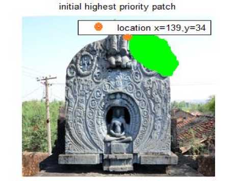
Figure 1(a) shows an image with a damaged portion which is closed by more than hundred boundary pixels as seen on the x axis components of figure1 (b). The priority for each of these points/pixels as calculated by using equation (1) is displayed as the y axis component of the figure 1(b). The combined highest priority is awarded to the patch number zero of the figure 1(b), which is associated with the pixel located at 139th row and 34th column of the image input, implying that the first patch filled will be the one around this pixel with chosen width w
Exterior boundary patch priotity graph
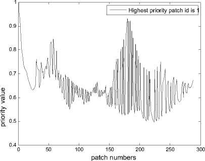
Fig. 1(a) highest priority patch (b) priority graph
As it goes with the property of standard deviation that higher deviation would cover more groups and hence much of information to be restored first if standard deviation is directly proportional to priority, it is observed in as depicted in fig(1), that the patch with higher standard deviation are chosen as first priority to fill, all of the pixels lying on borders of the background and foreground will be filled in a stretch, not considering the property of pixels in the neighborhood, resulting in more noise in restored image. Therefore the inverse of deviation is taken to start the filling from either from the interior of the foreground or exterior of the background and proceed towards centre of damage. The distance term in the priority ensures that filling of lower deviation (similar) patches is limited to a few in a row, choosing patches that are extreme from centre of damage in between. The border pixels between two different groups (fore and backgrounds) and centre of damage are one of the last to be filled, giving better results than standard deviation only as priority term.
-
B. Segmentation and patch selection
A patch from the source region is selected based on minimum distance in each of its constituent components from the destination patch. In this work we are implementing a patch refinement based on HOSVD which enables multiple feature inputs and filtering out and selection of prominent varying outputs. We select Kn nearest distance patches for each destination patch. This would definitely add to the execution time, as a counter we can limit the search space to a specific region only, and that is achieved by dividing the whole input into different groups using k-means segmentation. Now the search area is limited to the segment to which the centre pixel p of the destination patch belongs to. As a result the source area under search for suitable patches and hence time required is reduced significantly, especially in the images where variation is large. The k means clustering is implemented based on the center of group reference. Let us say image is to be divided in k groups then k reference centers are chosen and initial classification of each pixel is made, and labeled as per sum of square distance of each feature of the pixel from the reference as in equation(3).
G i,j = g : {argmin (ssd(I i,j , Cg))} (3)
Where Cg=centre of group g; g£ 1,2.. k, I= image
The selected nearest Kn patches are padded in extended columns
X=[p i , P 2 ..., P kn ] (4)
Here the dimensionality is n=3, row columns and depth for colors. However HOSVD is implemented by SVD in all these dimensions. Since SVD for two dimensional matrices is available readily, we make use of it by reducing n dimensional input to transformed two dimensional. The other dimensions are stretched keeping one dimension unchanged at a time, using matrix reshaping.
a i = T{Xt};where i = 1,2, ...n (5)
ai is resulting two dimensional matrix with transformation T with
T = RR]
R i = vector length of dimension i
R= the combined length of all other dimensions such that
R = 0 ^=1 R j , where j ^ i (6)
From data matrix available each of dimensions SVD is determined by
[U i , S i , V i ] = SVD(a i ); i = 1,2,.. n (7)
Here si is the matrix with singular values of ai as its diagonal elements. The columns of u i are the left singular vectors of s i , where as those of v i are right singular vectors. For filtering out values and selecting only the specific range, two thresholds obtained from r1 as lower limit and r2 as upper limit are used, the rows and columns of singular values which do not fall under the specified range/band are omitted. The range of singular values start from 0 to multiple of thousands based on the contrast values of contents, hence it is not possible to select a specific value for cut off limits to filter, instead we use the two limiting values r1 and r2 between 0 to 1, a value above 1 ideally selects the maximum value of threshold multiplied r2, since the highest values of Singular values matrix is significant the r2 is set to maximum, ie, r2=1. Selecting the lower range signifies the smoothness of the pixel variation in a patch, and we know a lower standard deviation implies smooth variations. Smoothness is also related the lower values of the S matrix. Hence the lower range r1 is taken to be least of the patch deviations around the damage. Since standard deviation is the value obtained with respect to the mean of a variable. Lower threshold is found around the mean of the S matrix. Converting these nominal range values to actual threshold value is as shown by equation (8)
The upper threshold t2
t2 = arg max(s) x r2 (8)
r2 = max(std(p)),Vp (9)
The lower threshold is smaller percentage of whole range and since minimum values of singular values typically start from 0 we can take maximum value to be the range of the singular values. Hence decide the lower threshold as in equation (9)
t1 = mean(s) x rl (10)
Where rl = min(std(p)), Vp (11)
The filtered rows and columns of the singular values are obtained by rejecting/eliminating singular values lower than lower threshold t1 and higher than the upper threshold t2. Bandwidth of the filter is r2-r1.
sf={ s‘,: t1^^^ (12)
( 0,: otherwise )
Reconstruction of the matrix from the above will give us the values that are refined and selected, the equation for reconstructing the data is given by (11)
a i = ut sf v' t (13)
The data thus obtained has a matrix for each dimension; a reverse transform to original dimensionality of the original data is from the average of the reconstructed data matrices eq. (12)
n
A = ^1 (14)
This refined patch to be pasted is obtained by choosing principal pixels equal to the size of the destination patch averaged for all dimensions.
-
IV. Experiment Simulation and Result Analysis
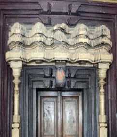
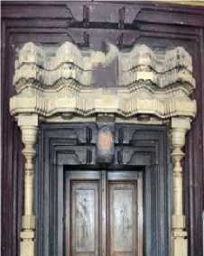
Following are some of the results; the two measures that are taken here for efficacy of the inpainting methods are PSNR and structural similarity. The quality parameter PSNR is most important when the damage is within the foreground of the monuments while the structural similarity (SS) plays role when the damaged area covers edge structures of the monuments. The PSNR and structural similarity though serve the purpose broadly there are few more parameters which are important in deciding the quality of an image such as mean square error (MSE), luminance(L), cross correlation(XK), absolute difference (AD), normalized absolute error (NAE) and structural content(SC)[19]. The error measures AD, NAE, MSE result in lower value for cases of better reconstruction, where as rest of parameters give a higher value for better results. To quantify the quality as single term using all the parameters, the error parameters are complemented by subtracting from the maximum possible value and normalized down, to take a quality factor Q to be the multiple of the modified measure parameters. The former is of most importance when the damage is within the foreground of the monuments while the latter plays role when the damaged area covers edge structures of the monuments. Q factor is defined as product of PSNR and SS. Results of proposed method are compared with tensor [4], alpha trimmed filter [16] and EBIIMPD [18] methods.
It is observed that variation of bandwidth of the filter in the mid-range have significant impact on the quality of output for a fixed combination of patch width and number of patches taken from source region for the damage. However higher number of patches kn adds to the quality of reconstruction, when the patch size is comparatively small and range are constant. When the patch size increases the more the kn patches more the overlap errors, resulting in better quality of output requiring less neighborhood patches. The lower and upper cut of ranges affect the selection of singular values of S matrix of SVD, since we are interested more in details and sharp edges of the structure we need higher singular values, the lower end values of S matrix constitute smoothness, far smooth values tend to induce errors, therefore a substantial lower cut of is necessary to eliminate the smooth values. This is done by mainly eliminating the zero values elements of the s matrix and corresponding left and right vectors, u and v. The results are shown in figure 2 for EBIIMPD [18], alpha trimmed filter[16], tensor[4] and proposed method(P). Table 1 depicts the performance parameters for Image 1 to 5.
a. ORIGINAL IMAGE
b. INPAINTING PORTION
Quality 26.1991
c. PRIORITY DEFINITION
METHOD
Quality 25.0527
d. ALPHA TRIMMED
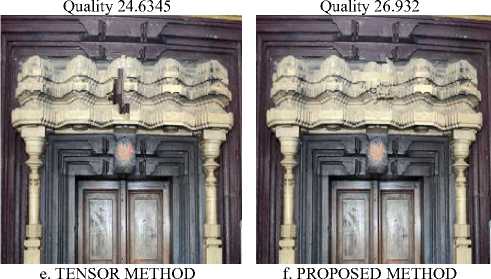
Fig.2. a) Original Image b) damaged region, (c) EBIIMPD [18] (d) Alpha trimmed filter[16] (e) tensor[4], (f) proposed method.
The performance parameters PSNR, Q and SS are tabulated in table 1. Proposed method gives better values for PSNR, Q and SS as compared to well-known existing methods. In all tables and figures w indicates width of the patches and Kn indicates number of similar patches.
Table 2 shows that the time required for reconstruction reduces with segmentation as the similar patches are searched within the segment and also improves the performance parameters.
Table. 2 Performance Parameters With And Without Segmentation For Image 1 And 2.
|
SS |
w |
Kn |
PSNR |
time |
|
|
with Segmentation |
0.9796 |
9 |
5 |
43.70 |
124.42 |
|
without |
0.9796 |
9 |
5 |
40.29 |
251.81 |
|
with Segmentation |
0.9796 |
21 |
5 |
40.72 |
39.71 |
|
without |
0.9796 |
21 |
5 |
40.78 |
71.49 |
Table. 1 performance parameters for image 1 to 5.
|
Image |
Method |
Q |
PSNR |
SS |
L |
MSE |
XK |
NAE |
AD |
SC |
|
I 1 |
E [18] |
31.18 |
32.13 |
0.98 |
1 |
1 |
1 |
1 |
1 |
1 |
|
A[16] |
33.17 |
33.93 |
0.99 |
1 |
1 |
1 |
1 |
1 |
1 |
|
|
T [17] |
32.94 |
33.57 |
0.99 |
1 |
1 |
1 |
1 |
1 |
1 |
|
|
P |
31.93 |
32.77 |
0.99 |
1 |
1 |
1 |
1 |
1 |
1 |
|
|
I 2 |
E [18] |
35.43 |
36.09 |
0.99 |
1 |
1 |
1 |
1 |
1 |
1 |
|
A[16] |
36.59 |
37.22 |
0.99 |
1 |
1 |
1 |
1 |
1 |
1 |
|
|
T [17] |
36.66 |
37.13 |
0.99 |
1 |
1 |
1 |
1 |
1 |
1 |
|
|
P |
37.33 |
37.91 |
0.99 |
1 |
1 |
1 |
1 |
1 |
1 |
|
|
I 3 |
E [18] |
32.39 |
33.41 |
0.98 |
1 |
1 |
1 |
1 |
1 |
1 |
|
A[16] |
33.12 |
34.08 |
0.98 |
1 |
1 |
1 |
1 |
1 |
1 |
|
|
T [17] |
31.57 |
32.59 |
0.98 |
1 |
1 |
1 |
1 |
1 |
1 |
|
|
P |
28.67 |
29.96 |
0.98 |
1 |
1 |
1 |
1 |
1 |
1 |
|
|
I 4 |
E [18] |
33.71 |
34.59 |
0.98 |
1 |
1 |
1 |
1 |
1 |
1 |
|
A[16] |
34.47 |
35.29 |
0.98 |
1 |
1 |
1 |
1 |
1 |
1 |
|
|
T [17] |
31.37 |
32.15 |
0.99 |
1 |
1 |
1 |
1 |
1 |
1 |
|
|
P |
34.7 |
35.34 |
0.99 |
1 |
1 |
1 |
1 |
1 |
1 |
|
|
I 5 |
E [18] |
33.61 |
34.22 |
0.99 |
1 |
1 |
1 |
1 |
1 |
1 |
|
A[16] |
35.75 |
36.24 |
0.99 |
1 |
1 |
1 |
1 |
1 |
1 |
|
|
T [17] |
34.39 |
34.89 |
0.99 |
1 |
1 |
1 |
1 |
1 |
1 |
|
|
P |
34.65 |
35.07 |
0.99 |
1 |
1 |
1 |
1 |
1 |
1 |
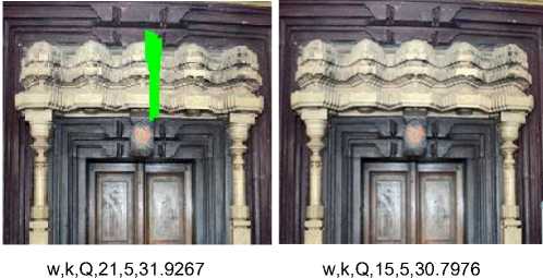
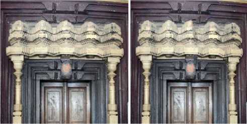
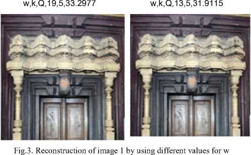
Table 3 shows the performance parameters for image1 and 2 for different values of w and Kn.. Q parameter is better for w=21 and Kn=5 hence these values are used for tabulating the results in table 1. Figure 3 shows the reconstructed images with performance parameters for different values of w with 13, 19, 21, giving reasonable Q factor.
Table 4 shows performance parameters for image1for different values of Kn and values of 4, 6, 7 giving good Q factor and table 5 shows performance parameters for image1for different values of w with w of 13, 15 and 17 having better Q factor.
For the damage which has very small coverage percent area smaller size of patch give better match, where as for input image with larger damage area the larger patch size gives better results. However too big a patch results into errors and hence lower PSNR, and a too small patch size over writes the pixels and results in errors, hence an optimum width is subject to the damage area size. Since the input image size is fixed to 256x256 pixels, the optimum patch size is dependent on the percentage area covered by the damage region.
-
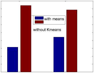
A. Impact of k means
Segmentation is mainly in terms of time optimization. The whole of the image since divided in 3 segments for experimental purpose, for an ideal combination of pixels in image, the time taken with k means segmentation would have been a third of that taken in case of sequential image scan through image. However practical cases differ from theory, some of the examples are depicted in figures 4, 5 and 6. The two cases of input images considered here with damage region covering 1.31% and 1.4% respectively. Figure 4 shows the time
taken for filling the damage region for both images with and without segmentation. It is clear that time optimization is better in case of segmentations .
time taken for execution
case image
Fig.4. Time optimization for segmentation
The segmentation for sure limits the source search area for a patch matching, hence in some cases the best match is the one that is limited to the segments and not whole image, resulting into lower quality of image reconstruction as shown in figure 5.
Q factor
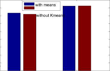
case image
Fig.5. Quality factor for segmentation
The quality of image in few cases without segments is slightly better than the segmentation case. That is the compromise that can be made as we can see that the total impact of quality and time is better in case of segmentation as depicted in figure 6. Figure 7 and 8 depicts the performance parameter Q for a data set of 100 images. The proposed method performs better than (green line)than the other methods.
Table. 3 Performance Parameters Of Image1, 2 For Values Of W And Kn.
|
W |
Kn |
Q |
SNR |
SS |
L |
MSE |
XK |
NAE |
AD |
SC |
|
9 |
5 |
34.61 |
35 |
0.997 |
1 |
1 |
1 |
1 |
1 |
1 |
|
9 |
7 |
34.41 |
34.80 |
0.997 |
1 |
1 |
1 |
1 |
1 |
1 |
|
21 |
5 |
35.67 |
35.89 |
0.997 |
1 |
1 |
1 |
1 |
1 |
1 |
|
21 |
7 |
34.87 |
35.09 |
0.997 |
1 |
1 |
1 |
1 |
1 |
1 |
|
9 |
5 |
41.79 |
41.89 |
0.998 |
1 |
1 |
1 |
1 |
1 |
1 |
|
9 |
7 |
40.46 |
40.59 |
0.998 |
1 |
1 |
1 |
1 |
1 |
1 |
|
21 |
5 |
38.77 |
38.94 |
0.997 |
1 |
1 |
1 |
1 |
1 |
1 |
|
21 |
7 |
40.06 |
40.18 |
0.998 |
1 |
1 |
1 |
1 |
1 |
1 |
Table. 4 Performance parameters for kn.
|
Kn |
Q |
SNR |
SS |
L |
MSE |
XK |
NAE |
AD |
SC |
|
3 |
29.55 |
30.58 |
0.99 |
1 |
1 |
1 |
1 |
1 |
1 |
|
4 |
32.84 |
33.63 |
0.99 |
1 |
1 |
1 |
1 |
1 |
1 |
|
5 |
31.93 |
32.76 |
0.99 |
1 |
1 |
1 |
1 |
1 |
1 |
|
6 |
33.15 |
33.92 |
0.99 |
1 |
1 |
1 |
1 |
1 |
1 |
|
7 |
32.28 |
33.09 |
0.99 |
1 |
1 |
1 |
1 |
1 |
1 |
Table. 5 Parameters for image1for different w
|
w |
Kn |
Q |
SNR |
SS |
L |
MSE |
XK |
NAE |
AD |
SC |
|
7 |
5 |
22.68 |
24.93 |
0.98 |
1 |
1 |
1 |
1 |
1 |
1 |
|
9 |
5 |
24.16 |
26.04 |
0.98 |
1 |
1 |
1 |
1 |
1 |
1 |
|
11 |
5 |
24.85 |
26.63 |
0.98 |
1 |
1 |
1 |
1 |
1 |
1 |
|
13 |
5 |
31.91 |
32.91 |
0.98 |
1 |
1 |
1 |
1 |
1 |
1 |
|
15 |
5 |
30.80 |
31.89 |
0.98 |
1 |
1 |
1 |
1 |
1 |
1 |
|
17 |
5 |
28.78 |
29.95 |
0.98 |
1 |
1 |
1 |
1 |
1 |
1 |
|
19 |
5 |
33.30 |
34.04 |
0.98 |
1 |
1 |
1 |
1 |
1 |
1 |
|
21 |
5 |
31.93 |
32.76 |
0.98 |
1 |
1 |
1 |
1 |
1 |
1 |
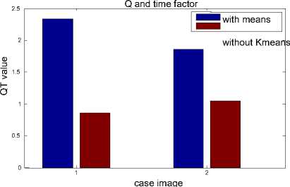
Fig. 6. Quality factor and time for segmentation
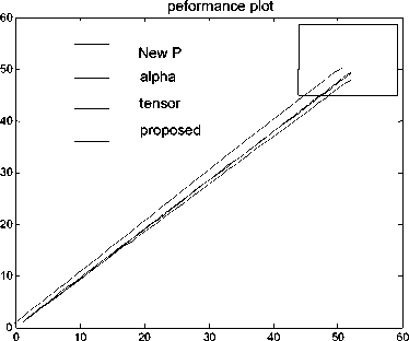
Fig.7. Performance plots of Q for a data set of 100 images.
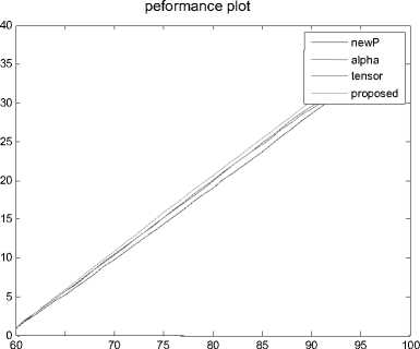
Fig.8. Performance plots of Q for a data set of 100 images.
-
V. Conclusion
Inpainting is a tricky matter at present since we attempt to bring about the image perception that has been damaged permanently, even though we use the PSNR along with few other quality measures to quantify quality recovery from the test sets, human perception only can be the best judge, as the images clicked may have lower light on some areas of monuments while reconstruction of the better lit closer patches result in lower Quality factor but better view of image reconstruction. A new method proposed to determine the Filling Priorities based on statistical and spatial properties performs better than other methods. Grouping of patches based on K means clustering improves the speed of reconstruction. Since the singular matrix is huge in size the lower values near zero are eliminated for better reconstruction. The results with the variations suggest that standard deviation applied for adaptive threshold decision helps for better results.
References Inpainting of structural reconstruction of monuments using singular value decomposition refinement of patches
- C Guillemot, O Le Meur, “Image inpainting: Overview and recent advances”, IEEE signal processing magazine, 2014.
- A. Criminisi, P. Perez, and K. Toyama, “Region filling and object removal by exemplar-based image inpainting,” IEEE Trans. Image. Process., vol. 13, no. 9, pp. 1200–1212, Sep. 2004.
- Fan Qian, Zhang Lifeng, Hu Xuelong, “Exemplar-based image inpainting algorithm using adaptive sample and candidate patch system”, 2015 IEEE 12th International Conference on Electronic Measurement & Instruments ICEMI'2015.
- Olivier Le Meur, Josselin Gautier Christine Guillemot, “Examplar-Based Inpainting Based On Local Geometry”, Image Processing (ICIP), 2011 ieeexplore.ieee.org.
- R. Martinez-Noriega, A. Roumy G. Blanchard, “Exemplar·Based Image Inpainting: Fast Priority And Coherent Nearest Neighbor Search”, 2012 IEEE International Workshop On Machine Learning For Signal Processing, SEPT. 23-26, 2012
- LIU Ying, LIU Chan-juan, ZOU Hai-lin, ZHOU Shu-sen, SHEN Qian, “A Novel Exemplar-based Image Inpainting Algorithm”, International Conference on Intelligent Networking and Collaborative Systems IEEE computer society.
- Kaushik kumar R. Patel, Lalit Jain, “A Novel Approach to Exemplar Based Image Inpainting”, IEEE Technology for Humanity.
- Ding Ding,, Sundaresh Ram, Jeffrey J. Rodriguez “Perceptually aware image inpainting”, Pattern Recognition journal www.elsevier.com.
- Y Qin, F Wang, “ A curvature constraint Exemplar-based image inpainting”, Image Analysis and Signal Processing (IASP),2010 ieeexplore.ieee.org.
- Yunqiang Liu and Vicent Caselles, “Exemplar-Based Image Inpainting Using Multiscale Graph Cuts”, IEEE Transactions On Image Processing, Vol. 22, No. 5, May 2013.
- Veepin Kumar, Jayanta Mukherjee, and Shyamal Kumar Das Mandal “Image Inpainting Through Metric Labeling via Guided Patch Mixing”, IEEE Transactions On Image Processing, Vol. 25, No. 11, November 2016.
- Qiang Guo , Shanshan Gao, Xiaofeng Zhang, Yilong Yin, and Caiming Zhang “Patch-Based Image Inpainting via Two-Stage Low Rank Approximation”, IEEE Transactions On Visualization And Computer Graphics, Vol. 24, No. 6, June 2018.
- Guibo Luo, Yuesheng Zhu,, and Biao Guo Fast “MRF-Based Hole Filling for View Synthesis”, IEEE Signal Processing Letters, Vol. 25, No. 1, January 2018
- Yi Ren, Yaniv Romano, and Michael Elad “Example-Based Image Synthesis via Randomized Patch-Matching”, IEEE Transactions On Image Processing, Vol. 27, No. 1, January 2018.
- Jiaying Liu, Shuai Yang , Yuming Fang and Zongming Guo “Structure-Guided Image Inpainting Using Homography Transformation”, IEEE Transactions On Multimedia, Vol. 20, No. 12, December 2018.
- Ding Ding , Sundaresh Ram and Jeffrey J. Rodríguez “Image Inpainting Using Nonlocal Texture Matching and Nonlinear Filtering”, IEEE Transactions On Image Processing, Vol. 28, No. 4, April 2019.
- Sarawut Akinori Nishihara, “Exemplar-Based Image Inpainting With Patch Shifting Scheme”.
- Deng L-J, Huang T-Z, Zhao X-L (2015) “Exemplar-Based Image Inpainting Using a Modified Priority Definition”. PLoS ONE 10(10): e0141199. doi:10.1371/journal.pone.0141199
- Song Wang Hong Li Xia Zhu Ping Li, “An Evaluation Index Based on Parameter Weight for Image Inpainting Quality”2008 IEEE computer society.
- Mrinmoy Ghorai, Sekhar Mandal, Bhabatosh Chanda A Two-Step Image Inpainting Algorithm Using Tensor SVD Published in ACCV Workshops 2014 DOI:10.1007/978-3-319-16631-5_5.
- M. G. Padalkar and M. V. Joshi, "Auto-inpainting Heritage Scenes: A Complete Framework for Detecting and Infilling Cracks in Images and Videos with Quantitative Assessment," in Machine Vision and Applications (MVA),vol. 26, no. 2–3, 317–337, March 2015.
