Intelligent Vision Methodology for Detection of the Cutting Tool Breakage

Author: Abdallah A. Alshennawy, Ayman A. Aly
Journal: International Journal of Information Technology and Computer Science(IJITCS) @ijitcs
Article in issue: 6 Vol. 5, 2013.
Free access
In this paper, a new Intelligent system based on neurofuzzy for detecting and diagnostics the wear and damage of the milling cutter is presented. The compatibility between the computer vision and neurofuzzy techniques is introduced. The proposed approaches consists of capturing the milling cutter image, Fuzzy edge detection, Chain code technique for feature extraction and finally, apply the neural network on the feature. The results of the study are three different diagnostics models, The first is diagnostic model for the original profile of the perfect cutter, the second is model for the wearied profile and the third is model for the damage profile. Experimental test results show that the proposed system is reliable, practical and can be used for the easy distinguish between the wear and damage automatically.
Intelligent Vision, Parts Classification, Chain Code, Diagnostics, Fuzzy Logic, Neural Networks
Short address: https://sciup.org/15011911
IDR: 15011911
Text of the scientific article Intelligent Vision Methodology for Detection of the Cutting Tool Breakage
Published Online May 2013 in MECS
In the field of the production engineering, some of the problems can be solved by the computer vision methodology. Such problems such as measurements and inspection of the dimensions, study the surface texture and so on [1-4]. There is study for An intelligent computer-aided radiologist diagnosis system based on fuzzy-neural and feature extraction techniques for detecting and diagnosing micro calcifications’ patterns in digital mammograms [5]. Another study using the wavelet fuzzy neural network for tool wear detection with cutting conditions and detected signals, which includes the model of wavelet fuzzy neural network with acoustic emission (AE) and the model of fuzzy classification with motor current [6]. The most different task to computer vision is in extract on knowledge from the information contained in the input image. The complete computer vision system as shown in Fig.1 is composed of three components, these are:
-
a) Image acquisition model: this model includes the CCD-camera and the interface card. This part is the eye of the system that is used to acquire an image for the inspected part and to send the image to the personal computer.
-
b) Personal computer: it is responsible for receiving the acquired image and to carry out the selected image processing algorithms on the image.
c) Image processing and pattern recognition module: this module is implemented as software program that manipulates the acquired image to get the necessary
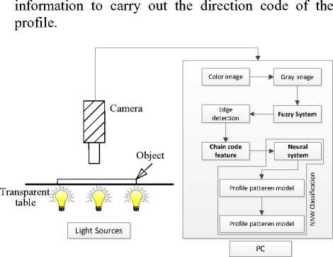
Fig. 1: Recognition Vision System
In this work, a computer vision methodology for automated inspection and diagnostic for wear and damage milling cutter is outlined. A commercial matrix CCD-camera with resolution [640 * 480] pixels connecting to a personal computer, which is occupied by an interface card, is used to build the experimental computer vision system. The captured color image is converted into gray image then the proposed algorithms are applied.
The remainder of the paper is organized as follows: In section II, a review of the necessary background required to effective implement of our algorithm is presented. The experimental result of the proposed algorithm for edges is described in section III. After that, application of the proposed algorithm is discussed in section IV, and we draw our conclusion in the last section.
-
II. Extracting the Edge Detection by Fuzzy Logic
Fuzzy image processing is the collection of all approaches that understand, represent and process the images, their segments and features as fuzzy sets. The representation and processing depend on the selected fuzzy technique and on the problem to be solved. Fuzzy image processing has three main stages: image fuzzification, modification of membership values, and, if necessary, image defuzzification as shown in Fig.2.
Fuzzy Logic ^---1

Profile Edges of the cutter
Mill Cutter Image


Image Fuzzification
Fuzzy Inference system
Expert Knowledege
Image Defuzzification
J
Fig. 2: The general structure of fuzzy edge detection
The fuzzification and defuzzification steps are due to the fact that we do not possess fuzzy hardware. Therefore, the coding of image data (fuzzification) and decoding of the results (defuzzification) are steps that make it possible to process images with fuzzy techniques. The main power of fuzzy image processing is in the middle step (modification of membership values).
After the image data are transformed from gray-level plane to the membership plane (fuzzification), appropriate fuzzy techniques modify the membership values. This can be a fuzzy clustering, a fuzzy rule- based approach, a fuzzy integration approach and so on, [7-11].
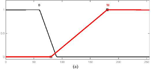
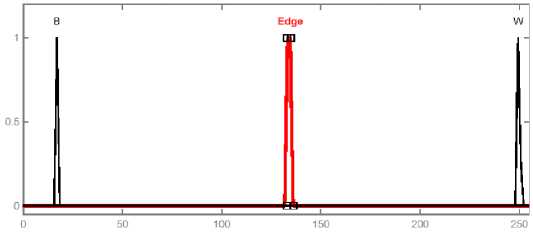
The system implementation is carried out considering that the input image and the output image obtained after defuzzification are both 8-bit quantized; this way, their gray levels are always between 0 and 255. The fuzzy sets are created to represent each variable’s intensities; these sets are associated to the linguistic variables “Black”, Edge and “white”. The adopted membership functions for the fuzzy sets associated to the input and to the output are triangles, as shown in Fig.3.
(b)
Fig. 3: Membership functions of the fuzzy sets associated to the input and to the output
The functions adopted to implement the “and” and “or” operations are he minimum and maximum functions, respectively. The Mamdani method is chosen as the defuzzification procedure, which means that the fuzzy sets obtained by applying each inference rule to the input data are joined through the add function; the
output of the system is then computed as the loom of the resulting membership function. The values of the three memberships function of the output are designed to separate the values of the blacks, whites and edges of the image.

Rule2
Rulel
Rule?
Rule3
Rule4
|
If {(hl, j-1 ) & Ci-1, j) if <0, j-1) &0, j) if {(i+1, j-1) & (i+1, j) |
& (i-1, j+1) } are whites & (i, j+1) } are whites & (i+1, j+1)} are blacks |
|
If {(H,j-1 ) & (i-1, j) If {(l, j-1) &(l, j) If {(i+1, j-1) & (i+1, j) |
& (i-1, j+1) } are blacks & (i, j+1) } are whites & (i+1, j+1)} are whites |
|
If {(i-1, j-1 )&(i,j-l) If{(bl,j) &(i, j) If {(i-1, j + 1) &(i, j + 1) |
& (i+1, j-1) } are blacks & (i + 1, j) } are whites & (i+1, j+1)} are whites |
|
If {(i-1, j-1 ) & (i, j-1) If {(Hl,j) &(l, j) If {(i-1, j+1) & (i, j+1) |
& (i+1, j-1) } are whites & (i + 1, j) } are whites & (i+1, j+1)} are blacks |
(a)
|
If {(i-1, j) & (i-1, j-1) & (i, j-1) & (i+1, j-1)} are blacks Rules If {(i-1, j+1) & [i, j+1] & (i+1, j+1) &(i+l, j)} checked pixel are whites is Edge If (i, j) is white |
||||||||
|
If {(i-1, j) & (i-1, j-1) & (i, j-1) & (i+1, j-1)} are RuleS If {(i-1, j+1) & [i, j+1] & (i+1, j+1) & (i+1, j)} checked pixel are blades B Edge If (i,j) is white If {(bl, j-1) & (i, j-1) & (i+1, j-1) & (i+1, j)} are Rule? If {(i-1, j) & (i-1, j+1) & (i, j+1) & (i+1, j+1)} checked pixel are whites 6 Ed^ If (i, j) is white |
|
|||||||
|
Rules |
Rule? |
|||||||
|
|
||||||||
|
If {(i-1, j) & (i-1, j+1) & (i, j+1) & (i+1, j+1)} are blacks Rules If {(i-1, j-1) & (i, j-1) & (i+1, j-1) & (i+1, j)} are checked pixel whites ® Edge If (i, j) is white |
||||||||
|
Rule6 |
RuleS |
|||||||
(b)
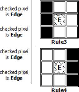
Fig. 4: Fuzzy inference rules
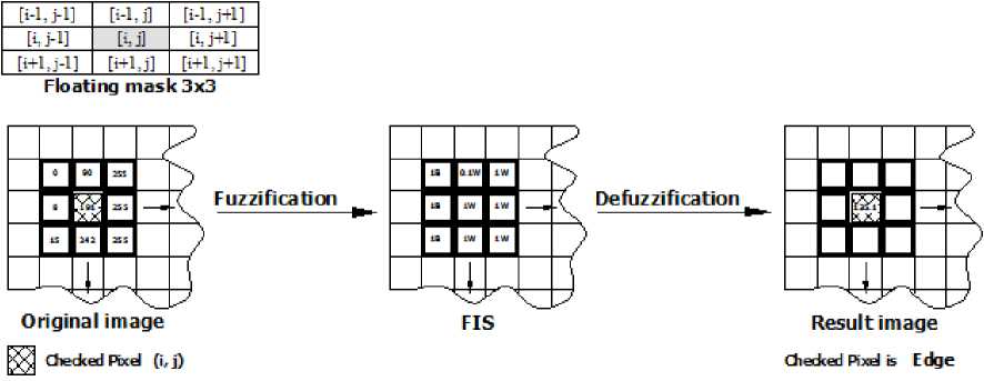
Fig. 5: Steps of Fuzzy Processing
The inference rules depend on the weights of the eight neighbours gray level pixels, if the neighbouring weights are degree of blacks or degree of whites. The powerful of these rules is the ability to extract all edges in the processed image directly. This study is assaying all the pixels of the processed image by studying the situation of each neighbor of each pixel. The condition of each pixel is decided by using the floating 3x3 mask which can be scanning the all grays [7].
In this location, some of the desired rules are explained. The first four rules are dealing with the vertical and horizontal direction lines gray level values around the checked or centered pixel of the mask, if the grays represented in one line are black and the remains grays are white then the checked pixel is edge (Fig.4-a ). The second four rules are dealing with the eight neighbors also depending on the values of the gray level weights, if the weights of the four sequential pixels are degree of blacks and the weights of the remain fours neighbors are the degree of whites, then the center pixel represents the edge (Fig.4-b). The introduced rules and another group of rules are detecting the edges, the white and the black pixels. The result images contribute the contours, the black and the white areas. From the side of the fuzzy construction, the input grays range from 0255 gray intensity, and according to the desired rules the gray level is converted to the values of the membership functions as shown in Fig. 5. The output of the FIS according to the defuzzification is presented again to the values from 0- 255. and then the black, white and edge are detected. From the experience of the tested images in this study, it is found that the best result to be achieved at the range black from zero to 80 gray values and from 80 to 255 meaning that the weight is white [7].
-
III. Experiment Result of the Milling Cutter Edges
The proposed system was tested with different images, its performance is compared to comparative base picture of perfect end mill. A presented nonlinear fuzzy filter, is based on applying local grouping of pixels within a 2-D moving window, such as a square mask, over the 2-D input image. The pixels inside the window are ranked according to their gray intensity values. The center pixel is classified into the local groups by using a fuzzy classifier. A pixel that is near an edge will ideally be combined with the neighboring pixels that lie on the same side of the edge,
The FIS system, in turn, allows edges to be detected even in the low contrast regions, this is due to the different treatment given by the fuzzy rules to the regions with different contrast levels, and to the rule established to avoid including in the output image pixels not belonging to continuous lines.
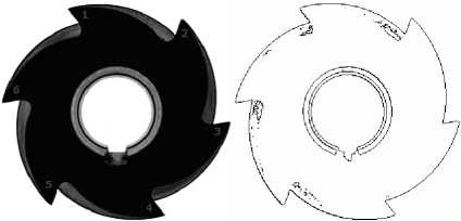
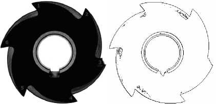
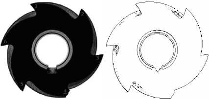
The original image is shown in part (a) of Fig. 6. where we use this image as comparative model for the classification process of crashed in Fig. 6 (b),(c) and worn in Fig. 6 (e), (d). The edge map of those images is detected using fuzzy technique with detailed in [7,8].
(a)
(b)
(C)
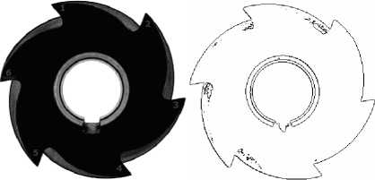
(d)
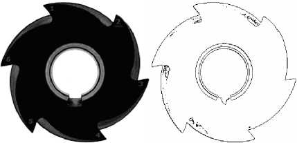
(e)
Fig. 6: (a) Reference captured picture for gear tooth and its edge map.
-
IV. Chain Code Representation
Boundary representations reduce object boundaries to a more compact or expressive form than the original boundary pixels. Popular methods include: Chain codes
– re-expressing the boundary as a sequence of primitive moves and Polygonal approximations – reduction to a close-fitting polygon Signatures [12,13].
Chain coding is a popular technique used to express gradual angular change along boundaries in images. Each direction of angular change is assigns a unique number and subsequently a boundary expressed as a numeric sequence. The chain code re-expresses boundary pixels as a series of pixel-to-pixel transition (direction codes), and is translation invariant. The chain code varies arbitrarily depending on the starting point (see Fig. 7). According to chain code method, angular changes from one pixel to the next, along a boundary, is expressed by a chain code. To obtain the boundary pixels, the image is mapped into a grad structure as shown in Fig. 8. However, these representations are sensitive to the starting point as well as scale and rotation. Chain code methods aime at representing gradual change of orientation along the object boundary. Therefore, it does not represent the overall appearance of an object which may be perceptually significant [1416].
i/y 6

Chain code
Start (x,y) - (4,2)
Profile code 65577881122
j/x
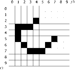
Fig. 7: Chain Code
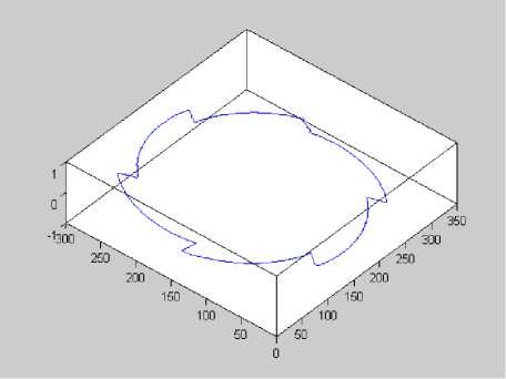
Fig. 8: The image is mapped into a gird structure
-
V. Neural Network Pattern Classification
Neural networks are commonly used for digital character recognition: partly because of their popularity and appeal, but undoubtedly they provide excellent results, perhaps among the best known for character recognition. The inherent pattern recognition abilities of layered neural networks lends itself perfectly to this type of task, by autonomously learning the complex mappings in high dimensional input data [17-22]. There are various forms of multi-layered neural network models, the most common and applicable to this task being the standard feed-forward connectionist model usually trained by way of backpropagation (gradientdescent). In general, multi-layered neural networks are said to perform a non-linear function of the linearly weighed sum of inputs in a distributed manner and can be very powerful. For more details see Appendix A.
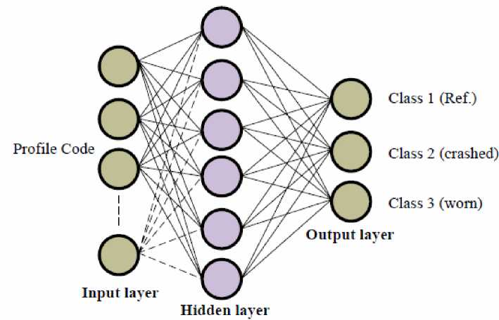
Fig. 9: Neural network architecture used for object classification
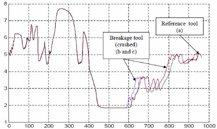
Fig. 10: the output of the NNW of the crashed cutting tools compared with the perfect one.
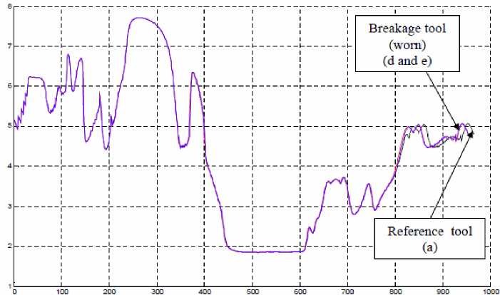
Fig. 11: the output of the NNW of the wearied cutting tools compared with the perfect one
This is the ability to recognize objects within a captured image. Such recognition requires the extraction of features from the image, such as edges or regions and the classification of these features to one of several pre-specified categories as shown in Fig. 9.
In Fig. 10 the NNW output of the crashed cutting tools compared with the model of the perfect one. The curves B and C lifted the perfect one suddenly where the difference between them is related to the order of the crashed teeth. However in Fig.11. the curves lifted each other gradually for the gradual nature of the wear.
-
VI. Conclusion
This work presents a new computationally efficient method designed for automatic pattern recognition of cutting tool failure. A fuzzy inference is used for edge detection, which is represented as chain code. The code is modeled by neural networks algorithm to classify the fault of the cutting tools, the shape of the diagram is different from the other as representing the type of the failure if fracture or wear. The effect of the wear is slightly affected and shafted from the reference profile, but the effect of the damage is dangerous and should be replaced by the milling cutter. The show results are promising, it can be employed in different application of the real world conditions.
References Intelligent Vision Methodology for Detection of the Cutting Tool Breakage
- Thomas R., "Computer Vision in Industry" in Artificial Intelligence in Engineering, John Wiley & Sons ltd 1991.
- Elias N. Malamasa, Euripides G.M. Petrakisa, Michalis Zervakisa, Laurent Petitb, " A survey on industrial vision systems, applications and tools "Department of Electronic and Computer Engineering, Technical University of Crete, Chania, Crete 73100, Belgium, Image and Vision Computing 21 (2003) 171–188
- B. J. Lei, Emile A. Hendriks, M.J.T. Reinders, On Feature Extraction from Images, MCCWS project, Information and Communication Theory Group TUDelft, Tuesday, June 01, 1999
- M.petrou, Learning in pattern recognition: some thoughts, Pattern Recognition Letters 22,3-13, 2001
- Verma B. and John Zakos, “A Computer-Aided Diagnosis System For Digital Mammograms Based On Fuzzy- Neural And Feature Extraction Techniques”, IEEE Transactions on Information Technology in Biomedicine, , volume. 5, March 2001.
- Yingxue Yao*, Xiaoli Li, Zhejun Yuan," Tool wear detection with fuzzy classification and wavelet fuzzy neural network " Department of Mechanical Engineering, Harbin Institute of Technology, Harbin 150001, People’s Republic of China Received 31 March 1998; received in revised form 22 January 1999
- Abdallah A. Alshnnaway, Ayman A. Aly, ”Fuzzy Logic Technique Applied to Extract Edge Detection in Digital Images For Two Dimensional Objects”, International conference in Production Engineering, METIP 4, 15-17 December 2006.
- Ayman A. Aly and A. A. Alshnnaway, "An Edge Detection and Filtering Mechanism of Two Dimensional Digital Objects Based on Fuzzy Inference", International Conference in Mechanical Engineering, ICME, pp. 247-251, Tokyo, Japan, May 27-29, 2009.
- B.-G. Hu, R. G. Gosine, L. X. Cao, and C. W. de Silva, ” Application of a Fuzzy Classification Technique in Computer Grading of Fish Products ”, IEEE Transactions on Fuzzy Systems, Vol. 6, No. 1, February 1998.
- S. Singh and A. Amin. Fuzzy Recognition of Chinese Characters, Proc. Irish Machine Vision and Image Processing Conference (IMVIP'99), Dublin, (8-9 September, 1999).
- Ayman A. Aly, H. Ohuchi and A. Abo-Ismail, “Fuzzy Model Reference Learning Control of 6-Axis Motion Base Manipulator”, 7th IEEE International Conference on Intelligent Engineering Systems, Luxer, March, 2003.
- Venu Govindaraju, Zhixin Shi CEDAR, Feature Extraction Using a Chain coded Contour Representation of Fingerprint Images, Department of Computer Science and Engineering, SUNY at Buffalo, Buffalo, NY 14260, John Schneider, Ultra-Scan Corporation, 4240 Ridge Lea Rd, Amherst, New York 14226 March 24, 2003
- Bryan S. Morse, Brigham Young University, Lecture 7: Shape Description (Contours),1998–2000, Last modified on January 21, 2000 at 2:20 PM
- Ahmet Denker and Tuˇgrul Adıg¨uzel, Vision Based Robotic Interception in Industrial Manipulation Tasks, international journal of computational intelligence volume 3 number 4 2006 issn 1304-2386
- S. Hoque K. Sirlantzis M. C. Fairhurst, A New Chain-code Quantization Approach Enabling High Performance Handwriting Recognition based on Multi-Classifier Schemes, Department of Electronics, University of Kent, Canterbury, Kent, United Kingdom, Proceedings of the Seventh International Conference on Document Analysis and Recognition (ICDAR 2003) 0-7695-1960-1/03 $17.00 © 2003 IEEE
- chung-hsien huang, jiann-der lee, jau-hua huang, Registration of ct image and facial surface data using adaptive genetic algorithm, Biomed Eng Appl Basis Comm, 2005(August); 17: 201-206.
- Laurence Fauselt, Fundamentals of neural networks., prentice-Hall, 1994.
- Haykin, S., Neural networks; A comprehensive foundation, Prentice-Hall,New-Jersey, USA, 1994.
- C. Bahlmann, G. Heidemann, H. Ritter, Artificial neural networks for automated quality control of textile seams, Pattern Recognition 32, (1999) 1049–1060.
- A.R. Novini, Fundamentals of machine vision inspection in metal container glass manufacturing, Vision’90 Conference (1990).
- Neural-Fuzzy Feature Detectors Harvey A. Cohen Craig McKinnon , and J. You, "Neural-Fuzzy Feature Detectors" " DICTA-97, Auckland, N.Z., Dec 10-12, pp 479-484.
- Editorial: Neural-Fuzzy Applications in Computer Vision Journal of Intelligent and Robotic Systems 29: 309–315, 2000. © 2000 Kluwer Academic Publishers. Printed in the Netherlands.
