Interference Rejection in FH/BFSK System Using Blind Source Separation

Author: Rafik Guellil, Hadj Abd El Kader Benzater, Mustapha Djeddou
Journal: International Journal of Information Technology and Computer Science(IJITCS) @ijitcs
Article in issue: 10 Vol. 8, 2016.
Free access
This paper introduces a new approach based on blind source separation (BSS) to mitigate intentional interference in BFSK digital communication systems using frequency hopping spread spectrum technique. The use of BSS is possible thanks to adopting an adequate selection block to distinguish between the useful signal and other undesirable signals, hence, circumvent the problem of ambiguity of permutation. An analytical calculation of the probability of error to predict the performance is done. The simulation results showed the effectiveness of this approach, whatever the level of the JSR and without using the fast frequency hopping alternative or error-correcting codes.
Blind source separation, frequency hopping, interference rejection, spread spectrum
Short address: https://sciup.org/15012566
IDR: 15012566
Text of the scientific article Interference Rejection in FH/BFSK System Using Blind Source Separation
Published Online October 2016 in MECS
The FH-SS technique is known to be robust against intentional narrow-band interference, and is widely used in military applications, wireless personal communications [1], and satellite communications [2, 3]. But its performance deteriorates sharply under Partial Band Noise Jamming (PBJN) or Multi-Tone Jammers (MTJ) [4] .
The performance studies of fast FH/MFSK communications systems using a variety of combinations of methods in the presence of MTJ and additive white Gaussian noise (AWGN) can be found in [4, 5]. An optimal structure for a Maximum Likelihood (ML) receiver, in fast FH-SS communication system with MTJ interference is given in [6]. It is shown that information about the noise variance, the amplitude of the signal, and the amplitude of the interference at each hop, as well as the calculation of modified Bessel non-linear functions are required to implement the optimal ML receiver. However, there is a price to pay when using fast hoping frequency. Synchronization between the transmitter and the receiver is difficult to realize. Studies on the slow FH-SS system in the presence of partial band interference were presented in [7, 8] and other effects about the reduction of dynamic jammers are described in [9, 10, 11].
An antenna array using Sample Matrix Inversion algorithm is used to isolate the desired signal from the interference signal [9]. Nevertheless, this algorithm assumes that the antennas have the same gain in the direction of interference and does not work properly for a quasi-static channel fading. The proposed algorithm in [10] has better performance for the dominant interference scenario. Nonetheless, it processes the received interfering signal as deterministic and unknown value to estimate. Thus, the less is the power of the jammer (or the signal to interference ratio), the less accurate is the estimation which leads to a deterioration in performance. This logic is completely reversed in the case of traditional ML algorithms where the jammer is considered as an additionally received noise.
In this paper, we propose to solve the problem (regardless of the jammer signal power to desired signal power ratio J/S) using blind source separation (BSS) and bypassing the problem of permutation ambiguity using a suitable block selection by taking into account the narrow bandwidth nature of the useful signal. The processing is carried out on a number of samples corresponding to a symbol period T b .
The rest of the paper is organized as follows: In section 2 the data model of the studied system is given followed by a brief discussion of the problems commonly encountered when using BSS techniques. Next, we give details about the proposed approach in section 3. In section 4, an approximate computation of the binary error probability is presented. Simulation results and discussions are followed-up in section 5.
-
II. D ATA M ODEL
Consider the case of a slow FH/BFSK system. To remove the harmful effect of the interference that covers all (or part) of the used band, a uniform linear array of m antennas followed by BSS algorithm block is used, we focus only on methods that use second order statistics. The output, y(t) of the antenna array can be modeled by the following equation:
where A ( m X n ) is the mixing matrix ( n is the number of sources, we limit our study to the case n =2 ), x(t) is the vector of sources given by x(t) = [s(t) j(t)] T with s(t) the useful signal and
j(t) is the interfering signal. w(t) is an awgn with zero mean and variance 7 2 .
If we do not take into account the attenuation of the channel (they are part of the estimated mixing matrix elements without any a priori information) and considering that we have a single jump by time period T b , the complex envelope of the transmitted signal is given by:
with < T is the power of the useful signal, f . , i = 1,2 is the obtained BFSK modulation frequency, and ∆f is the frequency hopping rate during the time interval T b .
Similarly, we model the jammer signal by:
j(t) - L a k expj(2nf k t+ф к )
k
° j
-
- L exP j (2 n fk t + v )
Where is the jammer signal amplitude for the 2
frequency component fk , CT j is the power of the jammer, B is the jammer signal bandwidth, and V k is a uniformly distributed random variable on [0, 2π], which makes the jammer a centered random process. In fact:
E[j(t)] = ;1 У[2"^ exP j (2nfkt+ Tk) dTk 2п T00
-
-^ E « k exP j(2 n fkt )[exP jVk 0 n j 2-n k
The ratio j means that the power is uniformly B distributed over the entire jammer’s band. Additionally, by considering the independence of the frequency components, the jammer is a centered random process with white behavior (in the studied band) with a variance °j:-
-
A. Inherent problems with BSS techniques
The use of BSS faces two main problems that are common to all methods, namely the ambiguity of permutation and scaling ambiguity. The first means that the order of signal restitution is arbitrary because any permutation applied on s(t) and a gives the same y(t).
This is true for any permutation matrix P (usually contains only 1 by row and by column) such that: A - AP and s ' (t) - P-1s(t) .
This problem can be avoided by using a priori information on the desired signal according to the application in hand. For example, in direct sequence spread spectrum systems (DS-SS) signals are spread by known orthogonal codes that allow to differentiate them from a jammer signal.
The second problem is similar to the permutation ambiguity where the multiplication of a column (of the mixing matrix) and a source division by a non-zero scalar does not change the vector x(t):
p
x(t) = Е а л( t )
i =1
- £ ( « в C s ? ] (5)
i -1 к P i )
This problem does not affect the FH-SS systems since the information is contained in the frequency, which is not the case of the DS-SS systems for example.
-
III. J AMMER I NTERFERENCE R EJECTION A PPROACH
The block diagram shown in the Fig. 1 illustrates the principle of the proposed approach to solving the problem of jamming in FH-SS. It should be noted that this type of solution was used for the first time in the DS-SS systems [12, 13] where it is possible to distinguish the useful signal using the sequences of pseudo-random codes. Unlike the DS-SS systems, we perform the despreading just before the separation block so that to feed the selection block (only takes into account the frequencies f1 and f 2 ). This latter operation is the principal element that allows the use of the BSS and then bypassing the problem of permutation ambiguity. In what follows, we describe the main components of the system.
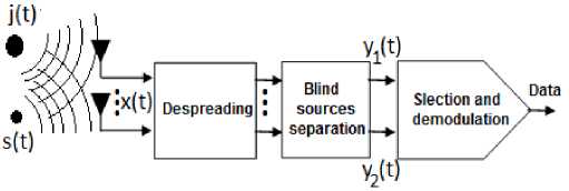
Fig.1. Spread Spectrum System using Blind Source Separation
-
A. Despreading operation
This is done by multiplying the received samples corresponding to a period jump (here T b ), by a local carrier of frequency Af . This is equivalent to multiplying the complex envelope of the received mixture of signals by exp( - j 2 nA ft ) , hence, translating the desired signal to the frequency f i i = 1, 2.
-
B. Separation bloc
To mitigate the effect of interference, the best solution is to separate the useful signal from the mixed one. This is done here by using the techniques of BSS looking to extract some or all of the signals constituting the received mixture signal y(t) with no information on the matrix A or the nature of the signals. The key feature of these techniques is that they are robust against multi-path effects and do not require that the antennas have the same gain. For cons, the assumption of statistical independence of the sources is the basis for the development of these techniques.
In the literature, several algorithms of the BSS are encountered [14, 15, 16]. In this paper, we chose the Second Order Blind Identification (SOBI) algorithm which has good performance and requires only the use of second order statistics, see [14] for more details about this well-known technique.
-
C. Selection operation
Because of the problem of the ambiguity of permutation, block selection is essential for the separation block output. To do so, we chose a strategy that takes into account the narrow bandwidth nature of the desired signal and the general principle is shown in Fig. 2.
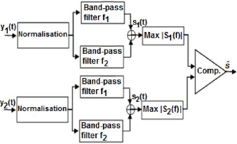
Fig.2. General Principle of Useful Signal Selection.
The first step to perform is signal normalization, In fact, this helps to bring the power of the two antenna’ outputs to the same level. Then each signal passes through two band-pass filters (in parallel) wedged on f 1 and f 2 whose outputs are summed. These two steps allow us to affirm (assuming a good separation) that:
-
• After filtering, only two frequency components f 1 and f 2 are kept.
-
• The jammer loses its power if it had many frequency components so that one of the components of the desired signal is stronger than both left frequencies of the jammer.
-
• If the jammer is initially narrow-band, it would be unlikely to fall in f 1 or f 2 after dispreading (FH-SS system itself is effective).
After, a comparison is carried out between the maximum values of the spectral power densities calculated at the outputs of filters each period Tb. We can approximate the power spectral density of a signal y(t) by:
psd = fft (y(t)) 2 (6)
Where fft is the fast Fourier transform.
And finally, BFSK demodulation is performed. For more precision in comparing only the powers in f1 and f2. A variant of the structure in Fig. 2, is shown in a Fig. 3. This structure can be used especially if the filters are not selective enough.
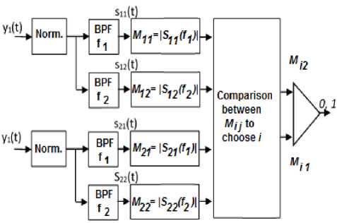
Fig.3. Used Selection/Demodulation Block
In this case, the maximum of the power spectral density is calculated at the output of each filter. A comparison between these maxima is used to select the desired signal for demodulation.
-
IV. B INARY E RROR P ROBABILITY D ERIVATION P e
In this section, we present an approximate theoretical calculation of Pe in the case of a perfect separation. This will allow us to predict the possible achievable performance and compare with the theoretical curves.
After despreading, the received signal at the antenna array for a useful signal of frequency f i is given by:
u(t) = s(t) + j(t) + w(t) = σ s exp( j 2 πf i t ) +
σ j ∑ exp j (2 π fkt + ϕ k ) + w ( t ) (7)
with σ2 is the power of the useful signal, and w(t) is a centered Gaussian white noise of variance σ2 and is w the bandwidth. In what follows, we consider the two cases: with and without selection operation.
-
A. Case without selection operation
In this case, the FH-SS system is used alone. The output of the band-pass filter (supposed ideal, magnitude one, and zero phase since it is the same for s(t) et j(t) ) keyed on f is given by:
u f ( t ) = σ s exp( j 2 πf i t ) + i
σ exp j(2πfit+ϕi) +w(t, fi) (8)
and thus the obtained maximum of the spectrum corresponding to f i is given by:
Mi = max Uf ( f )
In Fig. 4, P corresponds to the colored surface. It can be formulated as follows:
In the time domain, we take the expectation of three components constituting u ( t ) ;
fi
ifi s
- ( t - о )2 exp s
2 o 2
dt
So, u(t)is a random process of mean О and fi s variance О , with:
О2 о о
= -^ + — OL
BW
Similarly, the output of the band-pass filter tuned to fj , j * i , j e {1,2} is given by:
os /2 1
-” 2 ЛОо
О
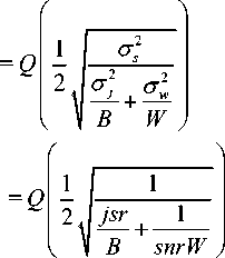
.. . o j ° with jsr = , snr = , and:
O s
о
w
The meanof u ( t ) is: f j
Q ( z )
1 JT

t 2
In the spectral domain, we take:
Mj = max Uf ( f )
In this case, u is a random process of zero mean j mj and variance О .
From these results, we can construct a decision rule where the decisive factors are the means m and m of the random processes u and u respectively.
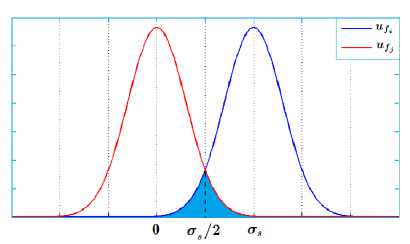
Fig.4. Probability Densities of u fi and u
fj
Figure 5 shows the sensitivity of the system to the presence of interference.
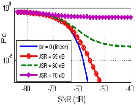
Fig.5. Binary Error Probability in the Case without Selection Operation
-
B. Case with selection operation
In this case, we use the logic block shown in Fig. 3. We denote by m the mean of the signal i ( i =1 for the useful signal, and i =2 for the jammer) over the output of the filter wedged to fj , j £ {1,2} .
If we put:
P = B ˆ A
_ ' a b л v c d ?
Where B is the estimate of the inverse of A , then the two outputs of the separation block are given by:
U ( t ) = a s ( t ) + b j ( t ) + wt ( t )
u 2 ( t ) = cs ( t ) + dj (t ) + w2 (t ) (18)
Without loss of generality, we assume that the separation is good enough to put a ; d ; 1 , and b ; c ; 0 (otherwise many cases have to be considered which conduct to a very tedious calculation). In this case, the equation (18) becomes:
Pe = PfP(df | cf) + (1 - Pf ) P(df | СГ)
the distributions of u and u are combined which means that P(df | cf ) =
For the computation, we must firstly determine the various intersections between distributions.
-
a) intersections between P and P u11
Equating the two distributions and taking the logarithm, we found the following result:
-
1 1 I a2 ( 2T s а, I T s I T 1 I — A (21)
—--2 I t -(—r) t + — + 2ln — I = U (21)
V T 1 T 2 ) T 1 T 1 V T 2 )
ux ( t ) = s ( t ) + W j ( t )
U 2 ( t ) = j ( t ) + W 2 ( t ) (19)
The discriminant of this equation is given by:
A' =
T 1 T 2
ст, 2 + 2ln T 2
s
2 -
>0
And in a similar manner to the case without selection operation, the second order calculation yield:
( T 2 > T 1 )
= E [ U J = T . So, U n is a random process with
Since the discriminant is positive, then there will always be two solutions given by:
2 tw mean m, and variance T--
11 1 kW
.
m = E [ u ] = 0 . So, u zero mean and variance T j2.
m = E [ u ] = 0 . So, u
is a random process with
is a random process with
, - „ =- tW 4-T zero mean and variance T---1.
m = E [ u ] = 0 . So, u is a random processwith
2 TW, T zero mean and variance T---1.
2 kW B
/ 1,2 T 2
T s ± T 12 JA
Here, that comes the interest of normalization and filtering steps. In fact, we can assume that T 2 ; T 2 jsrB , hence:
Y 1,2 = T s
|
D ±^ |
D |
1 + —1— ( D — 1)ln D _ snrkW _ |
( D - 1)
where T 2 is the noise variance at the input of the separation block, and k is the SNR factor of improvement (linear) delivered by the separation block (since SOBI estimates T 2)). This factor k will allow us to know the degree of improvement in term of SNR. The value of T 2 is given here for the case where no normalization is performed.
We also note that the means m , m , m , and m can be used to construct a decision rule.
In the sequel, we adopt the notation cf (resp. cr ) for a false choice (resp. right choice) of the useful signal, and df (resp. dr ) for a wrong decision (resp. right) of the bit value, then:
Where D = jsrB .
-
b) i ntersections between P et P u 12 u 22
This is a particular calculation of the precedent case by putting in (22) and (23) T = 0. There are two solutions Y and — Y , centered around 0, with:
D ln D
Y = T ----------
3 s M ( D — 1)( snrkW )
-
c) c alculation of P
Two cases can occur:
• Y 2 > У з :
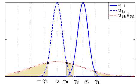
Fig.6. Probability Density of the Different U , i , j e {1,2} (Case
Y 2 > Y 3 )
In this case, P is equal to the colored surface as shown in Fig. 6 and consists of three parts:
P cf
V2 n^
Y 3
exp -
-^
t 2 U.
with:
2 Q (2l)+Q ( 2l) - Q (22) if y2> 2з p = I a2 a2 a2 (30)
Q ( 2 ^) + Q (- Y l) otherwise.
a 2 a 2
Y 2 < Y 3 )
V2na2
•2 2
dt
c +» t exp- —- dt Jyi P I 2a,2 J
• 2 2 < Y 3 :
In this case, the surface of the medium does not exist and we have:
V. S IMULATION R ESULTS
In this section, we examine the performance of the proposed scheme. In all the simulations, we take = 900 MHz, = 923 MHz, the number of possible jumps = 5 with steps of 5 MHz and a sampling frequency = 2.4 GHz, so we have a total bandwidth less than 50 MHz. Note that these parameters, specific to FH-SS system, are irrelevant in our case because the whole band is blurred. But it is clear that the greater the available bandwidth is large, and the number of frequency hopping, the more the system is robust against narrow-band interferer.
Figure 8 shows that without selection operation (in addition to filtering and demodulation) the system can not resist to the broadband interference, which is a predictable result by theoretical calculation.
d) c alculation of P ( df | cr )
This is a similar to the case without selection operation by setting jsr =0 . This means that:
In summary, P is given by:
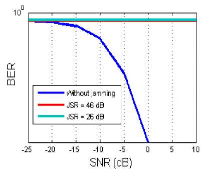
Fig.8. Bit Error Rate as a Function of SNR in the Case without Selection Operation
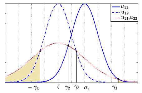
Fig.7. Probability Density ofthe Different U^ , i , j e {1,2} (Case
In the case of the proposed approach, we compared its performance against the only existing method in the literature on the broadband case. This method [10] is based on ML which is efficient but not general. In fact, we must initially check for the interference presence and dominance. This is depicted in Fig. 9. We see that the ML algorithm, once it decides that there is strong interference, gives a BER increasingly better while increasing JSR.
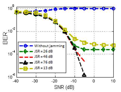
Fig.9. Bit Error Rate as a Function of SNR for ML
SNR (dB)
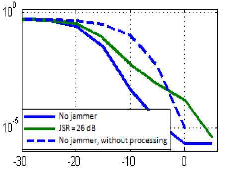
Fig.11. Comparison between the Proposed Algorithm and the Case without Selection Operation
Figure 12 shows that for both algorithms the BER stabilizes and becomes independent of the JSR value. Note that it is only after 15 dB that the ML algorithm is better than the proposed approach assuming we know in advance that the jammer is dominant. Before this value, the proposed algorithm performs better.
Note that in Fig. 10, BSS gives good performance whatever the power of the jammer, and we do not have to worry about jammer presence or dominance. We also note that the best result is given in the absence of the jammer, then slightly degraded curves are obtained for strong JSR.
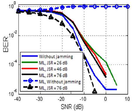
Fig.10. Bit Error Rate as a Function of SNR for the Proposed Algorithm
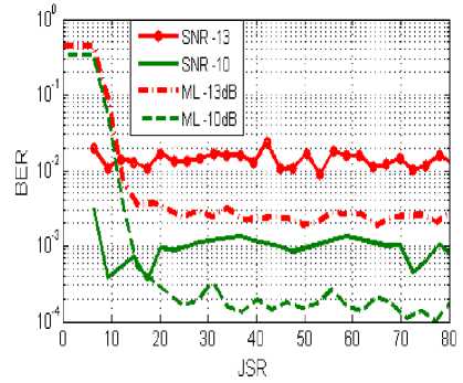
Fig.12. BER based on JSR
Based on the results of theoretical calculations developed in the case with processing (separation and selection) and according to the results in Fig. 11, we can deduce that indeed the SOBI algorithm improves the SNR at the output with a high factor ( к = 109 ).
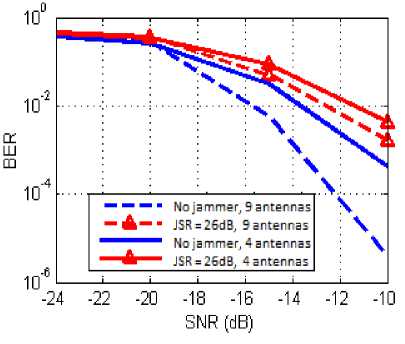
Fig.13. BER Versus SNR for 4 and 9 Antennas
It is interesting to see the effect of varying the number of antennas on the system performance. First, the ML algorithm has been developed for the case of only two antennas which makes it somehow fixed. Figure 13 shows that increasing the number of element from 4 to 9 can improve the BER significantly.
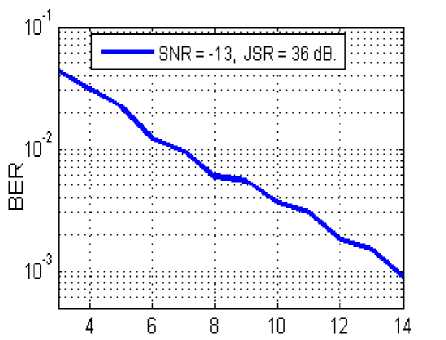
We can see this by plotting the BER improvement versus the number of antennas, which is shown in Fig. 14 for SNR = -13 dB.
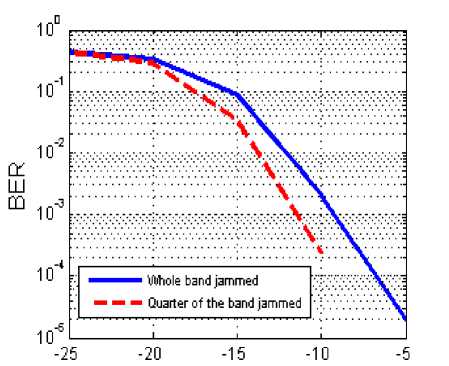
The bandwidth of the jammer is a very important parameter in this kind of problem. In Fig. 15, we see that if the jammer decreases the bandwidth to a quarter of the transmission band, then the BER decreases. This decrease is not very important because the power of the interference becomes more concentrated, and therefore more effective, but increasing the robustness of the system by frequency hop because some frequencies remain without interference.
Antennas number
Fig.14. BER Versus the Number of Antennas
SNR
Fig.15. BER Versus SNR
-
VI. C ONCLUSIONS
In this paper, we proposed an approach to solving the problem of the intentional jamming in the FH-SS system using BSS. The use of this latter technique permits a significant reduction in the bit error rate and the good performance of the system independently of the power ratio J/S even in the presence of noise causing low SNR. We also gave an approximate calculation of the probability of error that shows, as well as simulation results, the effectiveness of the proposed approach and the usefulness of the selection block that has overcome the problem of permutation ambiguity.
References Interference Rejection in FH/BFSK System Using Blind Source Separation
- T. Salonidis, P. Bhagwat, L. Tassiulas, and R. LaMaire. Distributed topology construction of bluetooth wireless personal area networks. IEEE Journal on Selected Areas in Communications, 23:633–643, Mar 2005.
- L. Simone, N. Salerno, and M. Maffei. Frequency-hopping techniques for secure satellite TT&C: system analysis & trade-offs. IEEE International Workshop on Satellite and Space Communications, pages 13–17, Sept 2006
- M. Pursley. Frequency-hop transmission for satellite packet switching and terrestrial packet radio networks. IEEE Transactions on Information Theory, 32:652–667, Sept 1986.
- H. M. Kwon, L. E. Miller, and J. S. Lee. Evaluation of a partial-band jammer with Gaussian-shaped spectrum against FH/MFSK. IEEE Transactions on Communications, 38:1045–1049, July 1990.
- C. Jiang and J. Wang. Multitone interference of fast FH/MFSK systems over Rician fading channels. IEEE Transactions on Communications, 1:309–313, May 1999.
- K. C. Teh, A. C. Kot, and K. H. Li. Performance study of a maximum-likelihood receiver for FFH/BFSK systems with multitone jamming. IEEE Transactions on Communications, 47:766–772, May 1999.
- J. J. Chang and L. S. Lee. An exact performance analysis of the clipped diversity combining receiver for FH/MFSK systems against a band multitone jammer. IEEE Transactions on Communications, 42:700–710, Feb 1994.
- R. Viswanathan and K. Taghizadeh. Diversity combining in FFH/BFSK systems to combat partial band jamming. IEEE Communications Letters, 36:1062–1069, Sept 1988.
- F. Eken. Use of antenna nulling with frequency-hopping against the follower jammer. IEEE Transactions on Antennas Propagation, 39:1391–1397, Sept 1991.
- C. C. Ko, H. Nguyen-Le, and L. Huang. ML-based follower jamming rejection in slow FH/MFSK systems with an antenna array. IEEE Transactions on Antennas Propagation, 56:1536–1544, Sept 2008.
- A. M. Alaa, H. Tawfik, Interference Mitigation Techniques for Spectral Capacity Enhancement in GSM Networks, IJWMT, vol.4, no.1, pp.20-49, 2014. DOI: 10.5815/ijwmt.2014.01.03
- M. F. Ghanim, M. F. L. Abdullah, Analysis of MC-CDMA System in Mobile Communications, IJITCS, vol.4, no.12, pp.87-94, 2012.
- A. Belouchrani and Moeness G. Amin. Jammer mitigation in spread spectrum communications using blind source separation. Signal Processing, 80 (723-729), 2000.
- A. Belouchrani, K. Abed-Meraim, J. Cardoso, and E. Moulines. A Blind Source Separation Technique Using Second-Order Statistics. IEEE Transactions On Signal Processing, 45:4, February 1997.
- J.-F. Cardoso and A. Souloumiac. Blind beamforming for non-gaussian signals. IEEE processing, 140:362–370, 1993.
- R. Mukai, S. Araki, and S. Makino. Separation and dereverberation performance of frequency domain blind source separation for speech in a reverberant environment. Proceeding of Eurospeech 2001, pages 2599–2603, 2001.
