Investigating Coupling Interactions in Split-Ring Resonator Dimers

Author: Akaa Agbaeze Eteng, Ngozi Peggy Udeze
Journal: International Journal of Wireless and Microwave Technologies @ijwmt
Article in issue: 2 Vol.13, 2023.
Free access
Topological wireless power transfer (TWPT) arrays provide directional power transfer, which are robust to external disturbances. Often realized as a chains of dimers, the ability to adjust the coupling between constituent resonator elements is an important means of establishing necessary conditions for power transfer. This paper explores the coupling interactions that are possible within dimers consisting of paired split-ring resonators (SRRs) in close proximity. Transfer efficiencies and through impedances are computationally studied for various rotational orientations of edge-and broadside-coupled SRRs. The obtained results reveal that relative rotational orientation can be employed as a sensitive design parameter to provide a variety of high- and low-coupling options within and between SRR dimers, with different power transfer efficiency implications.
Split-ring resonator, Coupling, Transfer efficiency, Dimer, Dipole moment
Short address: https://sciup.org/15019206
IDR: 15019206 | DOI: 10.5815/ijwmt.2023.02.01
Text of the scientific article Investigating Coupling Interactions in Split-Ring Resonator Dimers
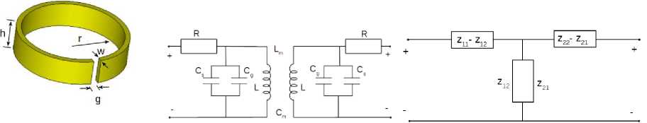
Split-ring resonators (SRR) are among the more widely encountered elementary particles of electromagnetic metamaterials and metasurfaces employed in various microwave and optical applications. These structures are characterized by small electrical sizes and strong magnetic responses at the resonant frequency [1]. In its basic form, an SRR is a metallic ring of sub-wavelength dimensions, with a small gap, as illustrated in Fig 1.
There are various applications which exploit interesting bulk properties realized when SRRs are arranged in arrays. One such application seeks to exploit the resonating features of SRRs in one-dimensional arrays to implement topological wireless power transfer (TWPT) [2,3]. These schemes utilize topological edge-states localized at the ends of a one-dimensional array of unit cells to provide directional power transfer, which is robust to external perturbations. The unit cells usually comprise of two closely coupled electromagnetic structures. A critical aspect of such arrays is the relationship between near-field intra- and inter-cell couplings. Various approaches employed to realize the required coupling relationships in these arrays include altering of intra- and inter-cellular distances [4–6], changing the winding direction of coil turns [7], and combining a resonant element with non-resonant counterpart in a unit cell [6].
Near-field-coupled SRRs are capable of exhibiting different coupling interactions in dimer configurations. Separation and relative orientations have been examined for their impact in SRR dimers at near-infrared frequencies [8]. In another study [9], the electric dipole moment has been shown to be the dominant coupling mechanism in a broadside-coupled SRR dimer when the gap-bearing side is parallel to the source E-field. In edge-coupled orientations, the coupling between SRR pairs has been shown to be either magnetic, electric, or a combination of both [10]. Subsequently, two rotational orientations of SRRs have been selected to establish strong intra- and weak inter-cell coupling in a TWPT chain composed of edge-coupled units [3]. However, these studies have assumed a limited choice of rotational options, and, except for [10], are largely silent on the transfer efficiency implications of each orientation. This paper, thus, seeks to broaden the investigations in [10] and [9] to include an examination of more rotational orientations between coupled SRRs, examining their coupling characterizations and the power transfer efficiency implications.
The rest of the paper is organized as follows. Section 2 describes the methodology employed in this study. First, an equivalent circuit model of a dimer comprising of a pair of identical SRRs is analyzed. This forms the basis of the setup employed for the numerical simulations, also discussed in this section. Section 3 provides the results of the numerical simulations, and discusses salient observations. The paper is concluded in Section 4.
2. Methodology
-
2.1 Equivalent Circuit Analysis
A dimer consisting of a coupled pair of similar split-ring resonators can be conceptualized using an equivalent circuit model, shown in Fig. 1b. The geometrically-defined lumped parameter values for each SRR can be formulated using the approach in [11], where the ring inductance is given by
Л 8( r + 0.5 w )
L = O x( r + 0.5 w ) l ln—-------- - 0.5 0 h + w
The gap capacitance across the split of width g is
C ~£ I hw Cg = £ 0 ^—
The surface capacitance of the structure is approximated by
CS = 2 £-0(h + w h4 ^ s n g
Equations (1) – (3) enable the determination of the self-resonance frequency of the SRR using
f 0 =
2 n LL (Cg + Cs )
The ohmic losses in the SRR are approximated by the resistance [12]
R = 2
nr + w/ '3 h
O f
a
^ , and o 0 represent free-space permittivity and permeability, respectively; while a is the material conductivity.
This equivalent circuit model can be transformed to a T-equivalent network using Z-parameters [13], shown in Fig 1c, so that the intra-cell coupling within a dimer is characterized using the through impedance z21 = j
2f
1 - (2 n f ) 2 L m C m
This expression assumes a non-negligible mutual capacitance C in parallel with the mutual inductance L between coupled SRRs.
(a) (b) (c)
Fig. 1. Split-ring resonator: (a) physical model (b) equivalent circuit model (c) T-equivalent network
-
2 .2 Simulation Setup
The SRR in Fig 1a is modelled for numerical simulations in CST Microwave Studio©. The structure is realized with the following dimensions: w = 1mm, h = 5mm, r = 10mm, and g = 1.5 mm. Analytically, these dimensions make for a resonance frequency of 2.08 GHz, which is used as an estimate to setup the solver parameters.
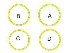
The numerical simulations investigate the impact of relative gap-orientations between two self-resonant SRRs. The study is executed for dimers comprising of edge-coupled and broadside-coupled SRRs. Each SRR is rotated in a plane normal to its axis to yield different relative rotational orientations when paired with another as a dimer, is shown in Fig. 2. For the edge-coupled SRR dimer, seven relative orientations are examined, while three relative orientations are studied for the broadside-coupled dimer. In both cases, the coupling interactions between the SRR units are examined at two coupling distances, namely x = 1 mm and x = 10 mm. In each case, the reactive component of the through impedance z 21 is plotted, along with the power transfer efficiency within the dimer, characterized using the transmission coefficient as
(a)
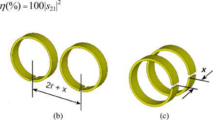
Fig. 2. SRR rotations and dimer alignments: (a) rotations (b) edge-coupled (‘DD’ orientation) (c) broadside-coupled (‘AA’ orientation)

3. Results and Discussion
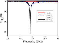
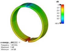
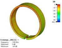
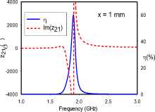
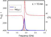
Pertinent simulated characteristics of the modelled SRR are shown in Fig. 3. In Fig. 3a, it can be observed that the resonance frequency of a single SRR from numerical simulations is 1.9 GHz. Also, the impedance characteristic is consistent with the behaviour of resonant parallel LC circuits, which connects with the insufficiency of a nominal 50 Ω input impedance, as revealed in Fig 3b. The parametric study shows that a much higher impedance is required to feed the SRR with minimal power reflection, which in practical terms can be achieved by exciting the structure with a high impedance probe [3]. However, for this study, a port impedance of 8kΩ is employed in a direct feeding arrangement. Fig 3c reveals that the electric energy in the excited SRR is concentrated in the vicinity of the gap. This implies that the electric dipole moment, spatially related to dense electric charge, is localized at the gap [14]. Conversely, Fig 3d shows that the magnetic energy is distributed over the inner surface of the SRR, and concentrated around the front and back rims. This implies that the magnetic dipole moment, due to circulating currents around the ring, is axial. Consequently, the electric and magnetic moments developed in an excited SRR are transverse to each other [14,15], with implications on the coupling that exists within a dimer.

-2000
-4000
-6000

Real Imag
(b)
1.5 2.0 2.5 3.0
Frequency (GHz)
(a)
(c)
(d)
Fig. 3. Single SRR characteristics: (a) through impedance; (b) parametric study of impact of input impedance on the reflection coefficient; (c) electrical energy density; (d) magnetic energy density
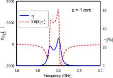
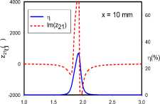
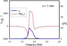
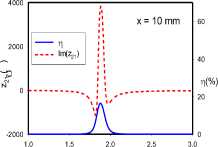
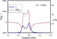
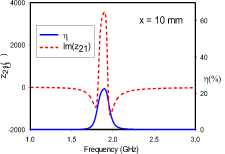
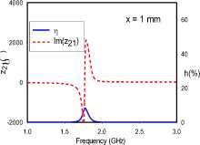
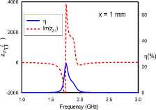
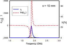
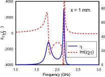
Figs. 4 and 5 reveal that the relative rotational orientation between coupled SRRs, at the studied coupling distances, is a significant factor affecting the coupling strength and power transfer efficiency within a dimer.
|
4000 |
} x = 1 mm |
60 |
4000 |
* x = 10 mm |
60 |
|
2000 |
2000 |
||||
|
д '''....... |
40 |
40 |
|||
|
J0 |
i — A |
T](%) |
0 |
11 (%) |
|
|
/1 |
|||||
|
-2000 |
Im(z21) |
20 |
-2000 |
Im(z21) |
20 |
|
-4000 |
.0 1.5 2.0 2.5 3 |
0 .0 |
-4000 1 |
.0 1.5 2.0 2.5 3 |
0 .0 |
|
Frequency (GHz) |
Frequency (GHz) |
||||
|
(a) |
(b)
(c)
(d)
(e)
(f)
(g)
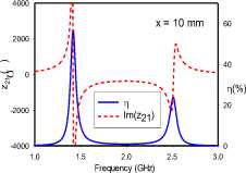
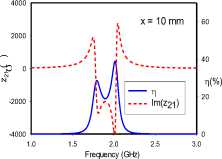
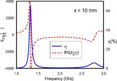
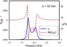
Fig. 4. Transfer efficiencies and through impedance of edge-coupled dimer for various rotational orientations: (a) ‘AC’, (b) ‘DD’, (c) ‘CA’, (d) ‘CD’, (e) ‘BD’, (f) ‘BC’, (g) ‘CC’
For the edge-coupled SRR dimer, Fig. 4 reveals frequency-splitting phenomena when the coupling distance is 1 mm with orientations ‘AC’, ‘CA’, and ‘BD’. This phenomenon, however, is absent for 1 mm separations with orientations ‘DD’, ‘CD’, ‘BC’, and ‘CC’. Orientations ‘CD’ and ‘CC’ achieve resonance at 1.75 GHz, while orientations ‘DD’ and ‘BC’ maintain the single SRR resonance of 1.9 GHz. Frequency-splitting does not occur in any of the studied orientations when the distance extended to 10 mm. At this distance, the previously split frequencies converge at the SRR resonance frequency of 1.9 GHz. Furthermore, it can be observed that for each frequency-splitting case at 1 mm, the realized transfer efficiency at 10 mm is approximately the same as the higher efficiency value of the split resonance frequencies.
Frequency-splitting is related to the strength and symmetry of the coupling electric and magnetic dipole moments, and a wider split is often indicative of stronger coupling [15]. In all rotational orientations (Fig 2a), the magnetic dipole moments are both transverse to the direction of coupling, and anti-symmetric, due to the reversed current directions in the coupled SRRs. On the other hand, the electric dipole moments are vertically oriented, parallel and anti-symmetric in the ‘AC’ and ‘CA’ orientations. The ‘DD’ orientation is characterized by collinear, horizontal and symmetric electric dipole moments. These moments are likewise vertically oriented, parallel and symmetric in the ‘CC’ orientation. In the ‘BD’ orientation, the electric dipole moments are horizontal, parallel and anti-symmetric. Lastly, the ‘CD’ and ‘BC’ orientations are cases were the electrical dipole moments in both SRRs are orthogonal, and hence do not couple significantly. Furthermore, the through impedance characteristics of the edge-coupled orientations suggest that the electric dipole moment coupling is the more dominant coupling mechanism in the ‘AC’ orientation, while magnetic dipole coupling is more significant in the ‘CA’, ‘CD’ and ‘BD’ orientations. Both dipole moments are, however, of comparable significance in the coupling realized in the ‘DD’, ‘BC’ and ‘CC’ orientations.
It is important to note that although the ‘CD’ and ‘BC’ orientations have similarly low electric dipole moment couplings, there is a difference in the coupling of their magnetic dipole moments. At the 1 mm separation with the BC orientation (Fig. 4f), the high charge density surrounding the gap of the C-oriented SRR is in close proximity with the near-side of the B-oriented SRR. It can be surmised that the resulting interaction disrupts current flow in the B-oriented SRR, which sufficiently attenuates its magnetic dipole moment, so as to lead to the lowest realized transfer efficiency of 8%. It is instructive to note that increasing the distance between both SRRs to 10 mm, lessens this interaction, and allows the transfer efficiency rise to 11%.
(a)
(b)
(c)
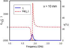
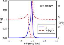
Fig. 5. Transfer efficiencies and through impedance of broadside-coupled dimer for various rotational orientations: (A) ‘AA’, (b) ‘BA’, (c) ‘CA’
All relative rotations of the broadside-coupled dimer setup in Fig. 5 exhibit frequency-splitting, except for the ‘AA’ orientation at 10 mm separation, where resonance converges at 1.9 GHz. Compared to the edge-coupled configuration, it can be argued that the axial orientation of magnetic dipole moments from the SRRs are responsible for the generally stronger coupling. Unlike the edge-coupled dimers, where the lower split-frequency has the higher transfer efficiency, the higher transfer efficiency occurs at either the lower or higher split-frequency. The results reveal a relationship between the symmetry of the coupling of magnetic dipole moments and the position of the split-frequency with the higher transfer efficiency. Symmetrical coupling, in this case, corresponds to the higher transfer efficiency occurring at the lower split-frequency, while the anti-symmetric case relates to the upper split-frequency having the higher transfer efficiency. The reverse observation is made with the coupling of transverse electric dipole moments.
The ‘AA’ orientation at 1 mm separation realizes the least frequency separation. The electric dipole moments are vertically aligned, and anti-symmetric. The magnetic dipole moments are similarly anti-symmetric. The split frequencies for this orientation converge with a transfer efficiency of 70% at 1.9 GHz for the 10 mm case. On the other hand, the BA orientation presents electrical dipole moments that are both offset from and orthogonal to each other, while the magnetic dipole moments are symmetric. Finally, the ‘CA’ orientation provides the widest frequency split. It is characterized by vertically aligned electric dipole moments acting in symmetry, but laterally offset from each other. The magnetic dipole moments in this case are also symmetric. For all orientations, the through impedance characteristic suggests a slightly more dominant electric coupling at 1 mm.
TWPT arrays typically require weak inter-cell and strong intra-cell coupling levels [2-5], with differing transfer efficiency characteristics implied. The results presented show that for edge-coupled SRRs, the ‘DD’ orientation is suitable for realizing a high transfer efficiency, while the ‘BC’ orientation is the best candidate for a low transfer efficiency. However, based on the spacing between split frequencies, the ‘AC’ orientation is best suited for establishing strong dimer intra-cell coupling, while the ‘BC’ arrangement is most suitable for a weak inter-cell coupling. The ‘CC’ and ‘CD’ orientations are also suitable options to provide low transfer efficiency coupling scenarios in the edge-coupled case. For broadside-coupled dimer structures, the ‘AA’ orientation is most suitable for a high transfer efficiency feature at a single resonance frequency, when the distance between SRRs is within a radius dimension. However, this orientation provides the weakest coupling. The ‘CA’ orientation, conversely, yields the strongest coupling level, as observed from the width of its split-frequency characteristic.
4. Conclusion
This study has examined the impact of rotational orientation on the near-field coupling between a pair of selfresonant SRRs in a dimer cell. Two dimer configurations have been examined, namely edge- and broadside-coupled alignments. In the edge-coupled setup, seven relative rotational orientations were examined, while three orientation were investigated for the broadside-coupled arrangement. These orientations were examined at two separation distances.
In all cases, the resulting transfer impedance and transfer efficiency between the coupled SRRs were numerically obtained. The results show that, even at tight coupling distances, the rotational orientation of a pair of SRR has a significant impact on the eventual energy coupling and the efficiency of power transfer interactions within a dimer. The significant variations in transfer efficiency values observed in this study provide a range of rotational orientation options suitable for establishing various combinations of intra- and inter-cell coupling characterizations for topologically invariant one-dimensional wireless power transfer arrays.
References Investigating Coupling Interactions in Split-Ring Resonator Dimers
- Zuffanelli S, Zamora G, Aguilà P, et al. On the Radiation Properties of Split-Ring Resonators (SRRs) at the Second Resonance. IEEE Trans. Microw. Theory Tech. 2015;63:2133–2141.
- Feis J, Stevens CJ, Shamonina E. Wireless power transfer through asymmetric topological edge states in diatomic chains of coupled meta-atoms. Appl. Phys. Lett. [Internet]. 2020;117:134106. Available from: http://aip.scitation.org/doi/10.1063/5.0024077.
- Jiang J, Guo Z, Ding Y, et al. Experimental demonstration of the robust edge states in a split-ring-resonator chain. Opt. Express. 2018;26:12891.
- Zeng C, Guo Z, Zhu K, et al. Efficient and stable wireless power transfer based on the non-Hermitian physics. Chinese Phys. B. 2022.
- Luo C, Qiu D, Lin M, et al. Circuit model and analysis of multi-load wireless power transfer system based on parity-time symmetry. Energies. 2020;13.
- Song J, Yang F, Guo Z, et al. Wireless Power Transfer via Topological Modes in Dimer Chains. Phys. Rev. Appl. [Internet]. 2021;10:1. Available from: https://doi.org/10.1103/PhysRevApplied.15.014009.
- Zhang L, Yang Y, Jiang Z, et al. Demonstration of topological wireless power transfer. Sci. Bull. [Internet]. 2021;66:974–980. Available from: https://doi.org/10.1016/j.scib.2021.01.028.
- Feth N, König M, Husnik M, et al. Electromagnetic interaction of split-ring resonators: The role of separation and relative orientation. Opt. Express. 2010;18:6545.
- Zhang F, Zhao Q, Sun J, et al. Coupling effect of split ring resonator and its mirror image. Prog. Electromagn. Res. [Internet]. 2012;124:233–247. Available from: http://www.jpier.org/PIER/pier.php?paper=11121808.
- Hesmer F, Tatartschuk E, Zhuromskyy O, et al. Coupling mechanisms for split ring resonators: Theory and experiment. Phys. Status Solidi Basic Res. 2007. p. 1170–1175.
- Sydoruk O, Tatartschuk E, Shamonina E, et al. Analytical formulation for the resonant frequency of split rings. J. Appl. Phys. [Internet]. 2009;105:014903. Available from: http://aip.scitation.org/doi/10.1063/1.3056052.
- Ejaz T, Rahman HU, Afaq S, et al. A Comparative Analysis of Split-Ring Resonator Models. 4th Int. Conf. Informatics, Electron. Vis. Fukuoka, Japan; 2015.
- Seo DW, Lee JH, Lee HS. Study on two-coil and four-coil wireless power transfer systems using Z-parameter approach. ETRI J. 2016;38:568–578.
- Baraclough M, Hooper IR, Barnes WL. Investigation of the coupling between tunable split-ring resonators. Phys. Rev. B. 2018;98:1–6.
- Seetharaman SS, King CG, Hooper IR, et al. Electromagnetic interactions in a pair of coupled split-ring resonators. Phys. Rev. B. 2017;96:1–7.
