IP Camera Based Video Surveillance Using Object's Boundary Specification

Author: Natalia Chaudhry, Kh. M. Umar Suleman
Journal: International Journal of Information Technology and Computer Science(IJITCS) @ijitcs
Article in issue: 8 Vol. 8, 2016.
Free access
The ability to detect and track object of interest from sequence of frames is a critical and vital problem of many vision systems developed as yet. This paper presents a smart surveillance system that tracks objects of interest in a sequence of frames in their own defined respective boundaries. The objects of interest are registered or saved within the system. We have proposed a unique tracking algorithm using combination of SURF feature matching, Kalman filtering and template matching approach. Moreover, an efficient technique is proposed that is used to refine registered object image, extract object of interest and remove extraneous image area from it. The system will track registered objects in their respective boundaries using real time video generated through two IP cameras positioned in front of each other.
SURF feature matching, template matching, Kalman filtering, track, IP cameras
Short address: https://sciup.org/15012532
IDR: 15012532
Text of the scientific article IP Camera Based Video Surveillance Using Object's Boundary Specification
Published Online August 2016 in MECS
Various network based video surveillance software are proposed in industry. There are many benefits offered by IP solutions. Beyond all such advantages, the use of coax cables has been eliminated. Network technology allows IP cameras to be administered and viewed, even though the operators are located far away. Video surveillance system finds events of interest in various aspects.
Many video surveillance systems have been introduced so far. One of them is NUUO surveillance system. It allows setting up the software to detect when defined objects are removed from areas being monitored by surveillance system. Apart from this, system for tracking a moving object, license plate recognition, face recognition and tracking, finding pedestrian in infrared videos, system for monitoring and alerting based on animal behavior and a system for detection of abnormal motion in video stream have also been introduced. The ability to detect and track object of interest from sequence of frames is a critical and vital problem of many vision systems developed so far.
The above mentioned systems notify the user merely on detecting motion and other activity. Each object of interest in a scene has common tracking criteria.
This paper introduces a video surveillance system that allows tracking of registered objects. The process of cropping out and saving object of interest from the given frame is referred to as registration of that object of interest. The proposed surveillance system will allow monitoring of different registered objects under a certain boundary that is defined and personalized for each object by the user and it notifies the user about theft of object only if it is found missing for predefined duration in its own defined boundary. This boundary is known as virtual fence for that object. If the object is flipped then the registered image of the object will not match with the current image of the object. Our video surveillance system caters this using an efficient algorithm known as auto-registration. In it, registered object image is modified and updated with object's current image to ensure correct object detection for monitoring in future.
Rest of the paper is organized as: Section 2 contains description of work done related to video surveillance. Section 3 describes the architecture of the system. Section 4 contains the description of each module involved in a system. Section 5 contains experiments and results. Section 6 concludes the paper. Section 7 contains future recommendations.
-
II. Related Work
Various surveillance systems have been developed to date. Vital task in each of these video surveillance systems includes object detection and tracking. Some of the video surveillance system projects are surveyed as follows. M. Sivarathinabala et al, [1] had proposed an intelligent video surveillance system. Human activity is recognized through image classification using HMM model. The system generates notification alarm when it detects abnormal activity through motion and event detection. H. Shengluan et al, [2] presented a tracking system that hinders the error that arises due to occlusion. This is done through estimations and predictions in Kalman filtering approach. It merely tracks the objects. Y. T. Hwang et al, [3] also presents a tracking system that is based on feature points. Object segmentation is eliminated to lessen the complexity. Feature points are detected and then matched to achieve matching. This matching is followed by tracking. C. Tuscano et al, [4] worked on a project of making a surveillance system that also notifies the user about intrusion, records and sends this footage to the user besides just detecting motion. Email and MMS are sent on discovering abnormal activity. Chandana had similarly proposed a system that detects motion and tracks object in a live video. Background subtraction technique is used for detecting motion [5]. A. Girgensohn et al, [6] proposed a multi camera indoor surveillance system named as Dynamic Object Tracking System. User will be notified about remote events. Integration with different sensors is done and interface is provided that allows the user to follow a person across series of cameras. Detection is done through technique of foreground segmentation. T. Yang et al, [7] introduced a multi-camera people tracking surveillance system that is robust. Approach based on greedy search is applied that efficiently tracks multiple people in the presence of occlusion. Moreover individual trajectories are associated in series of cameras that are adjacent to each other. The system proposed by X. Ke et al, [8] automatically checks the attendance of traffic controllers based on detection scheme. Detection and tracking scheme includes motion detection technique with feature matching and color segmentation. This helps to detect the object of interest accurately.
All of the above mentioned surveillance systems have same detection criteria for every object of interest present in a video frame. But the system proposed by us allows the user to customize the detection and tracking criteria for each object according to his or her needs. This is done by allowing the user to personalize and select the boundary (virtual fence) for each object of interest under which it should be tracked.
-
III. System Overview and Architecture
Our video surveillance system monitors and controls the theft of objects that are marked and registered by the user. User will be allowed to refine the registered object image to remove the irrelevant area from it for better tracking results. This will help to avoid false notification that may be due to irrelevant area existing in the registered object's image. The system will track the registered object efficiently even if the object changes its position. It checks if the object is stolen or not. In case of theft of registered object, system will notify and inform the user about it. The detailed working of main modules involved in our system is discussed in the next section. Two IP cameras are aligned in such a way that both of these face the front of each other. Due to this set up, one of the IP cameras captures the front side of object and other one captures its back side. This set up helps to deal with occlusion problems up to some extent. If one camera captures a scene of object being occluded due to some reasons (e.g., person standing in front of object and occluding its front side) then the other camera will capture its opposite side which is not occluded. Hence system will be able to detect the object in captured frame from the second camera. Objects of interest and their relevant virtual fences are cropped and registered in database. Frames are grabbed using these two IP cameras. Both of these frames are processed to find if the object exists in its virtual fence or
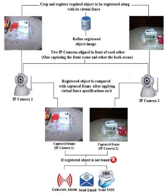
Fig.1. System architecture
not. This is accomplished by comparing these frames with the image of registered object that is registered within the system. Information regarding virtual fence is fetched from the database. If the registered object is not found for some predefined period in both of the frames captured by these two IP cameras then the system generates alarm, sends email and SMS based on user selection.
-
IV. Modules Involved in a System
Our video surveillance system helps the users to prevent theft and keep a track of different objects of interest in their own specified boundary. Refinement module includes cropping out the extraneous region from the image of registered object so that only intended registered object is included in the image. System will count the number of objects present in the image that makes it easy for the user to select and identify required registered object from these objects. Based on this user selection, objects and region other than intended object is cropped out and thus image will be refined. The most important module of the system is “Object Tracking”. This will track and monitor registered objects in frames captured by IP camera and check whether each registered object is in its virtual fence or not. If not, then through notification module user of the system will be notified about the theft. Notification module contains logic about notification.
The main modules involved in our video surveillance system are:
-
A. Registration of objects and their virtual fence
System tracks the object and check if that object has crossed a certain distance. The distance may vary from object to object as specified by the user. To handle the distance property we need to create some virtual fence for each object that specifies the boundary under which object should be tracked. On registration of objects that need to be tracked, system also needs to register and save the boundary parameters specified by user for each object. Registration is done through cropping algorithm. User is allowed to crop the desired object from frame along with its virtual fence and save it within the system. This process refers to as registration.
-
B. Registered objects Refinement
This module aims at improving the image of registered object to provide better results of tracking. When the user registers the object there may exists a possibility that the image of that registered object also contains other objects that does not intend to be tracked. Due to this negligence of user, the system will may not be able to know about absence of registered object due to existence of objects other than object of interest in the registered object image. To overcome this difficulty, this module allows the user to refine the image of registered object to crop out irrelevant region. This will eventually improve tracking results.
We have used the approach presented in the paper [9] for implementing this module with some proposed modifications. Threshold value is automatically calculated. Firstly, pyramid of input image is calculated. Pyramid down operation helps in calculating threshold value. Then, Laplace filter is applied for spot detection. After finding good spots and isolating them a threshold value is calculated on the basis of histogram operations. Initial estimated value of threshold is calculated by taking average of grayscale values in an image region. Final value for threshold is calculated by summing up the estimated value calculated and the value we get through histogram operation. Pixel intensity of each pixel of an image is compared with automatically calculated threshold value. If this intensity value is greater than the automatically calculated threshold value, the pixel is labeled as white in an image otherwise it is set as black. [9]
In this binary threshold image, some small regions may appear in an image due to noise. To overcome this, detected foreground objects that have less than 400 pixels are removed. On this, morphological closing operation is applied. [10] User is allowed to increase or decrease the final threshold value to get threshold image of his or her choice. Generally white pixels assimilate as foreground and black as background respectively. But due to intensity variations in an image there may arrive a case in which foreground appears as black and background as white. This is shown in Fig. 2 below. To cater this, we have devised a solution in which the system allows the user to choose whether white pixels correspond to foreground or black pixels corresponds to foreground. Based on this input the system labels and numbers the objects in an image. The user is allowed to give as input the number or label of the required object that need to be registered and tracked afterwards. Using this input, the system crops out and refine an image on the basis of height and width properties of labeled object. This is shown in Fig.3.
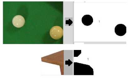
Fig.2. Binary images
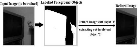
Fig.3. Refinement of image
-
C. Object tracking
After registration of objects, the next task is to track the object in their respective virtual fences to check whether they are stolen or not. For this, we need a mechanism to detect and match the object to verify its existence. SURF feature matching approach contributes to this. [11] We take current frame as query frame and image of registered object and then apply SURF feature matching algorithm on these two images. Using this, it can be figured out whether the object is in the query frame or not.
There may arises a case when SURF feature matching fails to detect registered object in its virtual fence even if that object is present in its virtual fence. Reasons may be the poor video quality due to which weak feature points will be detected thereby generating poor matches. So, to verify whether the result generated by SURF feature matching technique is true some other technique is needed that checks the availability of registered object in its virtual fence. If registered object is not found using SURF feature matching approach, then template matching approach is applied to detect whether the registered object is in its virtual fence or not. If template matching also indicate mismatch between registered object image and query frame only then appropriate notification actions would be taken. So template matching is used as a verification approach for finding theft. It is applied in tracking algorithm if and only if SURF feature matching fails to detect or find object in its virtual fence.
Template matching approach finds area in an image that has highest match. To find this area sliding window approach is used. That is, we slide template image patch on query image (source image). Patch is moved one pixel left to right and up to down. A metric is calculated at each image location that tells how well the match. Good match indicates that the patch is found in source image. [12] If template matching technique fails to detect registered object then it means that object is not in its virtual fence and appropriate measures should be applied. Fig. 12 illustrates the flow diagram of this module.
The tracking algorithm proposed by us does not involve SURF feature matching and template matching approaches only. We have proposed a unique algorithm for handling issues arising during tracking and increasing efficiency of tracking. We need to redefine and adjust virtual fence at appropriate times during tracking. This is discussed in detail in the next sections.
There are two sub modules for this module which are discussed in detail below. These are:
-
• Auto registration
-
• redefinition of virtual fence
-
D. Auto registration
After extracting out the detected image area it must be compared with registered object image already stored within the system to check if there is a significant amount of change or not. This will update already saved registered object image when it undergoes orientation change i.e. rotated or flipped. This process is known as autoregistration. Due to this the system will now detect and match the rotated or flipped registered object correctly as the already saved registered object's image is updated according to its current orientation. This ensures correct matching. This is shown in fig. 4.
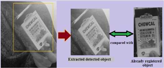
Fig.4. Auto registration process
In fig. 4, object is shown flipped thereby indicating orientation change. The image of registered object will be updated. Already registered object's image is updated with the extracted one. Due to this, updated image, as shown extracted in Fig.4 above, will be referenced for further tracking and flipped object will be accurately detected.
This must be handled efficiently because merely the illumination change or false detection can result in significant amount of change between detected area image and registered object image. So, simple motion detection may not correctly handle this. After experimenting with couple of images and scenarios we have devised a method for handling this and named it as double cross correlation template matching technique. Double cross correlation template matching is basically cross correlation template matching technique applied two times. First, the detected area image is used as first parameter for cross correlation algorithm with registered object image as a second parameter. That means we slide detected area image over registered object image giving a matching score as output. Second step is the inverse of first step in terms of inputs to cross correlation template matching algorithm. In it, registered object image is used as first parameter for cross correlation algorithm with detected area image as second parameter. That is, registered object image slides over detected area image. The match scores of these two operations are considered. This is shown in Fig. 5. In case of our verification approach of template matching (if the SURF could not find the registered object), apart from these two score matches, match score achieved by matching registered object in its virtual fence is also considered. After thorough experimentation, we have computed ranges that find whether the detected area needs to be auto registered or not. Ranges with their interpretation are shown in Fig. 6. "scr" is the difference of two match scores obtained by applying cross correlation two times in double cross correlation algorithm. "maxVal" is the match score achieved in template matching approach by detecting registered object in its virtual fence.
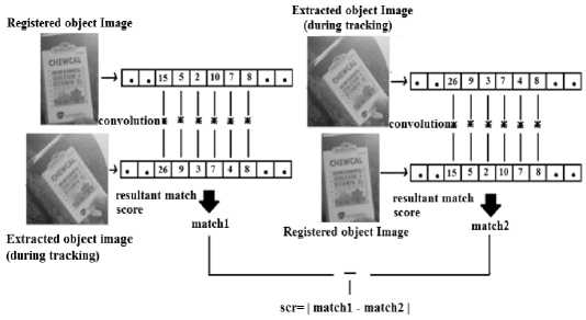
Fig.5. Double cross correlation template matching approach
|
Range |
Decision |
Tracking approach |
|
scr>=0.01 && scr<=0.099 |
Do not auto register |
SURF feature matching |
|
scr<0.01 and maxVal>=0.5 |
Do not auto register |
Template matching (if SURF feature matching failed to detect object) |
|
scr>=0.01 && scr<=0.06 and maxVai>=0.5&& maxVakO.6 |
Do not auto register |
Template matching (if SURF feature matching failed to detect object) |
|
scr>=0.09 && scr<0.7 and maxVal<0.75 |
Do not auto register |
Template matching (if SURF feature matching failed to detect object) |
|
scr>=0.1 && scr<0.3 and maxVal<0.6 |
Fake detection Do not auto register |
Template matching (if SURF feature matching failed to detect object) |
|
scr>=0.1 and (maxVat>=0.72 || maxVal>=0.5 || maxVal<0.6) |
Auto register |
Template matching (if SURF feature matching failed to detect object) |
Fig.6. Ranges with their interpretation
-
E. Redefinition of virtual fence
For tracking the registered object image of large size in its virtual fence the tracking algorithm tends to run slow due to this. Specially in case of template matching, the larger template image is slow to process. To avoid this one way is to find the registered object in an area around that point inside a virtual fence where the registered object is last detected. The size of that area is calculated with respect to size of registered object image. As in two consecutive frames the registered object should have not gone too far in virtual fence. So area with size calculated with respect to size of template image will be sufficient. That is we need to redefine virtual fence. This redefined virtual fence will be under the boundary of originally defined virtual fence by the user. At first, the point at which the registered object is detected is considered. That point’s x and y coordinates are recorded that serves as centroid for the next area (redefined virtual fence) that needs to be redefined in original virtual fence for detection purpose. Then this centroid is processed and rectangular virtual fence is created. Width and height of that rectangular redefined virtual fence is double the width and height of registered object's image. This process is illustrated in Fig. 7 and Fig. 8 below.
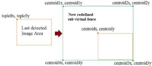
Fig.7. Mapping of previous detection
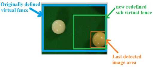
Fig.8. Redefined sub virtual fence creation
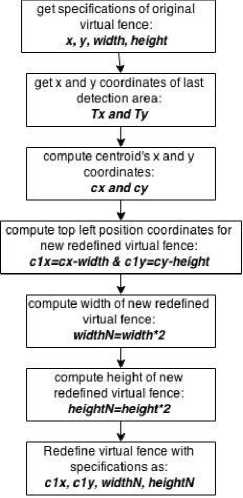
Fig.9. Redefinition of virtual fence
The sub virtual fence defined within the original virtual fence may go out of boundary of originally defined virtual fence during processing. So its existence must be guaranteed inside virtual fence only.
As the virtual fence is redefined the system will not be too slow in processing the large fences. But there may arise an issue. If the object is moving and not detected in some frames then we may miss the points of detection that will be used for redefining fence in the next frame. Due to this the sub fence created will not be updated and object will eventually move out of it. Although the object may exists in originally defined fence but as the redefined fence is not updated so object will not be tracked. This is shown in Fig. 10 in which the redefined fence is shown not updated. To handle this we have used Kalman filtering optical flow analysis approach to serve the purpose. The detailed working of the same is described in [13]. A small history about x and y coordinates position of detected area is maintained for each iteration. Kalman filter gives as output the position coordinates of motion detected area. We are using Kalman filter in our surveillance system as an estimator of position of moved object in a frame. First of all Kalman filter is applied that gives the position where the motion is detected i.e. the position where the object might be moved. Position at which the object is detected in last frame is adjusted with this value. After this the virtual fence is redefined using the procedure described above. If the object is moved and is not detected in last frame then due to this adjustment the fence will be updated according to the position parameters of object due to its motion. So even if the object is not detected for some reasons then the position parameters will not be missed and the fence will be redefined. Fig. 11 illustrates the flow diagram of approach adopted for virtual fence adjustment.
Originally defined virtual fence redefined sub virtual fence
Detected object
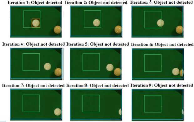
Fig.10. Issue in redefinition
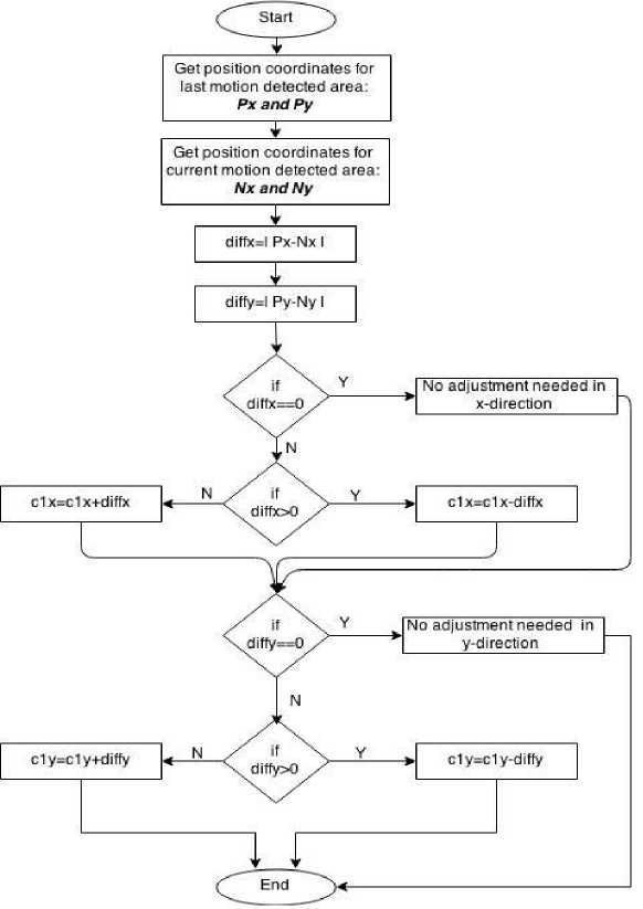
Fig.11. Virtual fence adjustment
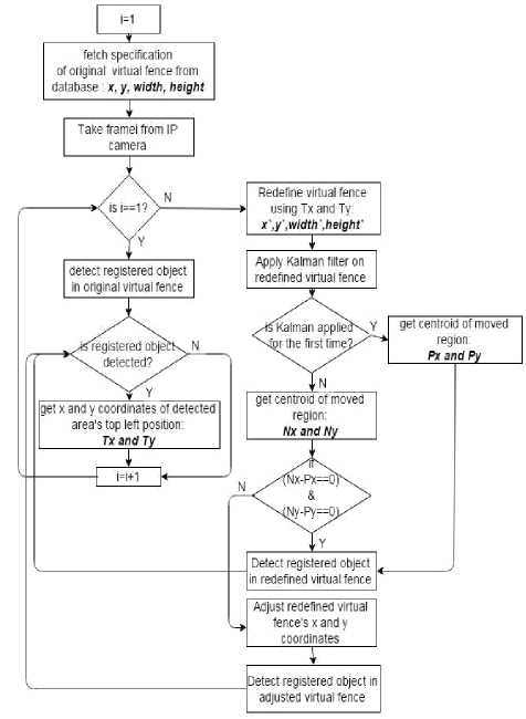
Fig.12. Object tracking
-
F. Notification of theft
This module involves informing the user about theft. When any registered object got stolen and it is not found in some specified number of frames then the system notifies the user about it. Three categories of notification are catered by our system. These are:
-
• Generation of alarm
-
• Sending SMS
-
• Sending Email with an attachment of footage with
theft scene.
User is allowed to select any of these categories and the system will do action accordingly.
-
V. Experimental Results
The algorithms and approaches discussed in the above section are implemented in MATLAB 2013a and tested for three different objects using two IP cameras. Objects include laptop, mobile and duplicate objects. Different scenarios are derived and considered. The algorithm is tested for each scenario.
-
A. Formulas used
Scenario efficiency=No. of frames satisfying the scenario/No. of frames taken*100(1)
Scenario frame rate=Frames taken/time taken(2)
Overall efficiency=∑ No. of frames satisfying the scenario /∑ No. of frames taken*100(3)
Overall frame rate=∑ Frames taken/∑ time taken(4)
Scenario error=No. of frames not satisfyingthe scenario/No. of frames taken*100(5)
Overall error=∑No. of frames not satisfyingthe scenario/∑No. of frames taken*100(6)
-
B. Results categories and scenarios
Table 1. Possible results and their meanings
|
Result Category |
Assigned |
Meaning |
|
True positive |
1 |
Result says that object is detected and requirement is that object should be detected. |
|
negative |
1 |
According to results object is not detected in virtual fence. In actual, object is not in fence and hence should not be detected. |
|
positive |
0 |
According to results object is detected in virtual fence. In actual, object is not in fence and hence should not be detected. |
|
negative: |
0 |
According to results object is not detected in virtual fence. In actual, object is in fence and hence should be detected. |
Table 2. Scenarios
|
Scenario 1 |
Object is inside its "virtual fence and not moving. |
|
Scenario 2 |
Object is outside its virtual fence. |
|
Scenario 3a |
Object is inside its virtual fence and rotated with an angle of 135 degrees |
|
Scenario 3b |
Object is inside its virtual fence and rotated with an angle of 90 degrees |
|
Scenario 3 c |
Object is inside its virtual fence and rotated with an angle of 45 degrees |
|
Scenario 4 |
Object is inside its virtual fence and being moved. |
|
Scenario 5 |
Object is inside its virtual fence and occluded. |
-
C. Objects used in experiment

Fig.13. Laptop
Fig.14. Mobile

Fig.15. Duplicate objects
-
D. Results with laptop
Virtual fence width: 311
Virtual fence height: 133
Table 3. Results using laptop
|
Laptop as a registered Object |
||||||
|
Scenario |
frames satisfy! ng the score of 1 |
frames satisfy* in g the score of 0 |
taken |
taken (in secon ds) |
Scenario Efficienc |
Scenario frame |
|
Scenario 1 |
213 |
2 |
215 |
168.9 8 |
90.06% |
1.27 |
|
Scenario 2 |
61 |
6 |
67 |
68.7 |
91.04% |
0.975 |
|
Scenario 3a |
21 |
1 |
22 |
32 |
95.45% |
0.68 |
|
Scenario 3b |
31 |
0 |
31 |
41.02 |
100% |
0.75 |
|
Scenario 3c |
13 |
0 |
13 |
21.23 |
100% |
0.61 |
|
Scenario 4 |
125 |
11 |
136 |
179 |
91.91% |
0.75 |
|
Scenario 5 |
23 |
10 |
33 |
52.27 |
69.69% |
0.63 |
|
Total |
487 |
30 |
517 |
563.2 |
- |
- |
Overall efficiency = 487/517*100 = 94.19%
Overall frame rate = 517/563.2*100 = 0.917
-
E. Results with mobile
Virtual fence width: 226.98
Virtual fence height: 110.98
Table 4. Results using mobile
|
Mobile as a registered Object |
||||||
|
Scenarios |
frames satisfying the score |
frames satisfying the score |
frames taken |
taken (in seconds) |
Scenario efficiency |
Scenario |
|
Scenario |
119 |
0 |
119 |
82.63 |
100% |
1.44 |
|
Scenario |
119 |
0 |
119 |
76.78 |
100% |
1.54 |
|
Scenario |
5 |
3 |
8 |
5.19 |
62.5% |
1.54 |
|
Scenario 3b |
9 |
2 |
11 |
6.65 |
81.81% |
1.65 |
|
Scenario |
17 |
0 |
17 |
11.81 |
100% |
1.43 |
|
Scenario |
93 |
0 |
93 |
61.81 |
100% |
1.5 |
|
Scenario |
37 |
11 |
48 |
38 |
77.08?/» |
1.26 |
Total 399 16 415 282.87
Overall efficiency = 399/415*100 = 96.14%
Overall frame rate = 415/282.87*100 = 1.46
-
F. Results with duplicate objects
Virtual fence width: 466
Virtual fence height: 271
Table 5. Results using duplicate objects
|
Duplicate Objects |
||||||||
|
Scenarios |
detection |
No. of frames ng the score of 1 |
No. of frames ng the score of 0 |
Horizontal distance between objects |
Vertical distance between objects |
No. of frames |
take |
Efficiency score |
|
Scenario 1 |
wrong |
10 |
0 |
58 |
6 |
10 |
9.4 |
10 |
|
Scenario 1 |
right |
5 |
0 |
57 |
5 |
5 |
6 |
5 |
|
Scenario 1 |
right |
7 |
0 |
55 |
62 |
7 |
6.8 |
7 |
|
Scenario 1 |
right |
5 |
0 |
56 |
67 |
5 |
5.1 |
5 |
|
Scenario 1 |
wrong |
7 |
0 |
81 |
28 |
7 |
7.3 |
7 |
|
Scenario 1 |
right |
73 |
0 |
89 |
13 |
73 |
70.7 |
73 |
|
Scenario 2 |
wrong |
0 |
73 |
89 |
13 |
73 |
89.3 |
0 |
|
Scenario 3 |
right |
43 |
20 |
79 |
27 |
63 |
97.3 |
43 |
|
Scenario 4 |
right |
45 |
23 |
0-75 |
0-75 |
68 |
1122 |
45 |
|
Total |
195 |
116 |
564 |
221 |
311 |
404.1 |
195 |
|
Overall efficiency = 195/311*100 = 62.70%
Overall frame rate = 311/404.1*100 = 0.76 frames/s
The tracking efficiency achieved by using laptop and mobile as a registered object is above 90% and acceptable. For duplicate objects, efficiency of scenario in which object is not present in the virtual fence is 0. This is because although the object intended to be tracked is removed from virtual fence there exist the other duplicate object. So the system detects and tracks that duplicate object present in virtual fence. If there is no restriction that only the original intended object must be detected or tracked rather than its duplicate then this scenario efficiency would be 100%. For other scenarios the efficiency is acceptable because after first iteration the system tracks the object in redefined. This means that the correct detection will depend on the distance between two objects and specifications of virtual fence. If the distance between the two duplicate objects is large and the virtual fence is broad enough to be redefined then this will lead towards correct detection. But the first detection will be anonymous. The system will may detect the intended original object or it may detect the other duplicate one. The system will detect that first detected object onwards in next frames after the first detection, until the other duplicate object is placed next to this object.
-
VI. Conclusion
In this paper, a smart surveillance system is presented that can track objects of interests in their respective virtual fences. The previously proposed systems do not have virtual fence specification property. Moreover, we have presented an efficient unique tracking algorithm that combines different approaches together to provide efficient results. We have integrated various algorithms to avoid false alarms and do correct detections and tracking. In the end we presented the results and discussed some implementation related issues and future directions. We have provided our model for the development of video surveillance system with virtual fence customization and would like to urge prospective researchers to explore this field further as it needs more attention.
-
VII. Future Recommendation
Further improvements in speed and efficiency of system are needed. The algorithm can be extended to handle tracking of multiple registered objects simultaneously. Occlusion must also be managed. Issues in tracking that may arrive due to blurred objects and objects with reflective surface must be appropriately handled. For duplicate objects, adjustments can be made to correctly detect object especially for the first time.
References IP Camera Based Video Surveillance Using Object's Boundary Specification
- M. Sivarathinabala and S. Abirami, "An Intelligent Video Surveillance Framework for Remote Monitoring," in International Journal of Engineering Science and Innovative Technology, Vol. 2, 2013.
- S. Huang and J. Hong, "Moving object tracking system based on camshift and Kalman filter," in Consumer Electronics, Communications and Networks, pp. 1423-1426, 2011.
- Y.T. Hwang et al., "Feature Points Based Video Object Tracking for Dynamic Scenes and Its FPGA System Prototyping," in Intelligent Information Hiding and Multimedia Signal Processing, pp. 325 - 328, 2014.
- C. Tuscano, et al. "Smart Web Cam Motion Detection Surveillance System," in International Journal of Modern Engineering Research, Vol. 3, pp-1169-1171, 2013.
- S. Chandana, "Real time video surveillance system using motion detection," in India Conference, pp. 1-6, 2011.
- A. Girgensohn, et al. "DOTS: support for effective video surveillance," in Proceedings of the 15th international conference on Multimedia. ACM, pp. 423-432, 2007.
- T. Yang, et al. "Robust people detection and tracking in a multi-camera indoor visual surveillance system," in International Conference on Multimedia & Expo, 2007.
- K. Xiang, et al. "Intelligent video surveillance for checking attendance of traffic controllers in level crossing," in Journal of Shanghai Jiaotong University, Vol. 19, pp. 41-49, 2014.
- M. Shneier, "Using Pyramids to Define Local Thresholds for Blob Detection," in Pattern Analysis and Machine Intelligence, IEEE, Vol. 5, pp. 345 - 349, 1983.
- A. Bishnoi, "Noise Removal with Morphological Operations Opening and Closing Using Erosion and Dilation," in International Journal Of Modern Engineering Research, Vol. 4, 2014.
- H. Bay, T. Tuytelaars and L.V. Gool, "SURF: Speeded up robust features," in European Conference on Computer Vision, Vol. 3951, pp. 404-417
- Tutorials on Opencv template matching approaches and implementation algorithms working. Available: http://docs.opencv.org/doc/tutorials/imgproc/histograms/t emplate_matching/template_matching.html
- C. Suliman, C. Cruceru, and F. Moldoveanu, "Kalman filter based tracking in an video surveillance system," in Advances in Electrical and Computer Engineering, pp. 30-34, 2010.
