Эффект усадки бетона в композитных балках

Автор: Хаджалич Эмина, Баручия Касим
Журнал: Строительство уникальных зданий и сооружений @unistroy
Рубрика: Строительные материалы
Статья в выпуске: 11 (26), 2014 года.
Бесплатный доступ
В статье анализируется напряжение в составной балке, усадка бетонной плиты во временной зависимости. В дополнение к аналитическому решению напряжения опытных образцов, выполнено численное решение с помощью программного комплекса SAP2000 V 16. Для линейного поведения элементов различных диаметров, жесткость определяется с использованием конечно-элементной модели, сравнение численных и аналитических решений распределения напряжений показано. Деформация усадки определяется с помощью EC2. В целях модели из конечных элементов, этот штамм преобразуется в эквивалентную нагрузку температуры.
Композитная балка, бетонная плита, усадка, жесткость, метод конечных элементов
Короткий адрес: https://sciup.org/14322065
IDR: 14322065 | УДК: 69
Concrete shrinkage effects in composite beams
The text analyses stresses in composite beam, as a result of time - dependent concrete slab shrinkage, where in addition to analytical solution of stress distribution, numerical solution is given as well, using structural software SAP2000 v 16. For linear behavior of the headed stud anchors, whose stiffness for varying diameters is determined using separate finite element model, a comparison between numerical and analytical solutions of stress distribution is shown. Shrinkage strain is determined using EC2. For purposes of the finite element model, this strain is converted into equivalent temperature load.
Текст научной статьи Эффект усадки бетона в композитных балках
Shrinkage is time - dependent irreversible deformation which causes the reduce in volume of unloaded concrete due to loss of water. Factors with the most influence on the value of shrinkage strain are the ambient humidity, the dimensions of the element and the composition and quality of concrete.
In composite beams, due to compatibility conditions, shrinkage of concrete part of the cross - section (concrete slab) results in an unfavourable redistribution of stresses. When losing water, concrete tends to shrink, in other words deformation of shortening tends to happen. However, steel part of the cross - section prevents concrete of deforming freely. As a result of restrained deformation, tensile stresses appear in concrete slab. Due to equilibrium, compressive stresses in the steel part of cross - section must appear as well [1].
The aim of this paper is to form a simple numerical model which will sufficiently accurate represent distribution of stresses in composite beam due to shrinkage of concrete slab. Regarding that, comparison between analytical and numerical obtained solution for a different points in time is shown [1-22].
Properties of composite beam
Cross - section of the composite beam consists of the steel part - IPE 400 and the 12 cm thick concrete slab. Based on the expressions given in EC2, creep coefficients which were used to determine the effective Young's modulus of elasticity are calculated [2].
Table 1. Properties of the concrete and the steel part of cross - section
|
Concrete |
Steel |
||
|
C25/30; f ck [N/mm2] |
25 |
S355; f y [N/mm2] |
355 |
|
Young's modulus of elasticity E cm [N/mm2] |
31 000 |
Young's modulus of elasticity E a [N/mm2] |
21 000 |
|
Slab thickness h c [cm] |
12 |
Area A a [cm2] |
84,50 |
|
Effective width b ef [cm] |
300 |
Moment of inertia I a [cm4] |
23 130 |
Table 2. Properties of the composite beam cross - section in time "t"
|
Point in time t [days] |
7 |
28 |
1000 |
∞ |
|
Creep coefficient φ |
0 |
1,2 |
2,7 |
3,0 |
|
Effective Young's modulus of elasticity of concrete [N/mm2] |
31 000 |
14 091 |
8 378 |
7 750 |
|
n=E a /E b |
6,77 |
14,90 |
25,07 |
27,10 |
|
Area A i [cm2] |
615,93 |
326,06 |
228,12 |
217,36 |
|
Moment of inertia I i [cm4] |
78 918 |
68 347 |
60 817 |
59 640 |
Table 3. Properties of the headed stud anchor
|
Tensile strenght |
f u =450 N/mm2 |
|
Young's modulus of elasticity E [N/mm2] |
21 000 |
|
Diameter Ф [mm] |
16 and 25 |
|
Height [mm] |
100 |
|
Longitudinal spacing [cm] |
14,6 |
Construction of Unique Buildings and Structures, 2014, №11 (26)
Analytical solution
Shrinkage is unavoidable in material such as concrete. As it was said in introduction, because the deformation of concrete is restrained it results in tensile stresses in concrete slab and compressive stresses in the steel beam. In other words, composite beam is self - stressed and no external reactions are induced at the supports. The value of these stresses depend on the stiffness of the cross - section. Another time-dependant property of concrete is creep. Creep is time - dependent increase in deformation as a result of sustained stress. The effects of creep are being taken into account through effective Young's modulus of elasticity, in other words by reducing the stiffness of the cross - section. This reduction in stiffness leads to decrease in value of stresses caused by shrinkage.
In a relatively dry ambient the expected value of shrinkage strain of unrestrained concrete slab is 0.03% of the slabs length or higher. However, in composite beam the expected value of shrinkage strain is lower because concrete slab can't deform freely [3].
In Eurocode 2, the expression for determining the value of shrinkage strain are given as a function of the relative humidity (RH), the notional size of the cross - section (h o ), the concrete strenght class and the type of the cement. The total shrinkage strain is composed of the drying shrinkage strain and the autogenous shrinkage strain: [2]
S cs =S cd +S ca (1)
Normal hardening cement CEM 32.5 for a concrete strength class C25/30, relative humidity RH=70% and the notional size of the cross - section h 0 =11,54 cm the values of the shrinkage strain of concrete for which solidification process began after one day (according to Eurocode 4) are given in next table:
Table 4. Values of shrinkage strain
|
Point in time |
ε cd [10-6] |
ε ca [10-6] |
ε cs [10-6] |
|
t=7 days |
15,41 |
40,56 |
55,97 |
|
t=28 days |
24,49 |
132,55 |
157,04 |
|
t=1000 days |
37,43 |
357,86 |
395,29 |
|
t=to |
37,50 |
375,51 |
413,01 |
After the values of the shrinkage strain have been determined, distrubution of stress along the cross -section height for selected points in time is calculated on the assumption of the full shear connection i.e. there is no slip between concrete slab and steel beam. For a given point in time, properties of idealised cross - section are calculated taking into account corresponding creep coefficient. Obtained stress distribution is shown in Figure 1.
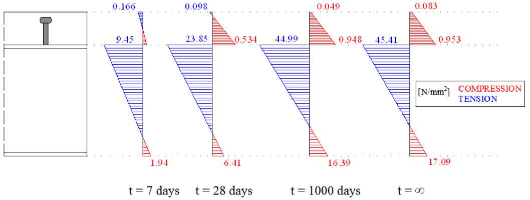
Figure 1. Distrubution of stresses σ x [N/mm2] along the cross - section height
It should be noted that these stresses are only important for serviceability limit state because they cause deflection which can be significant. [3] In ultimate limit state due to plastification, for classes of steel cross -section 1 and 2, the steel beam no longer offers resistance to concrete shrinkage. As a result, the stresses caused by shrinkage of concrete slab disappear.
Numerical model
Following elements were used for numerical model of composite beam:
-
- SHELL elements – rib and flange of steel beam,
-
- SHELL / SOLID elements – concrete slab,
-
- LINK elements – headed stud anchors.
Concrete slab can be modelled with SHELL elements whics have 4 nodes and 4 Gauss integration points or with SOLID elements which have 8 nodes and 8 Gauss integration points. [4] In general, for slabs with simple geometry and constant thickness, as in this model, it is more practical to use SHELL elements. SOLID elements can be used for slabs with complex geometry.
Along the "x" axis, the model is divided into 81 elements and in every node one LINK element which simulates headed stud anchor is associated. Calculation is conducted for linear elastic LINK elements with varying values of stiffness which depend on the diameter of the headed stud anchor. The stiffness of LINK elements for diameters Φ16 and Φ25 mm are determined on numerical model shown in 4.1. Models with finite element mesh are shown in Figures 2 and 3.
In this example because linear elastic behaviour is assumed, headed stud anchors could have been modelled with FRAME elements as well. However, LINK elements were used instead with which eventual nonlinear analysis could be conducted.
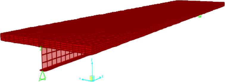
Figure 2. Numerical model – variant I (concrete slab modelled with SOLID elements)
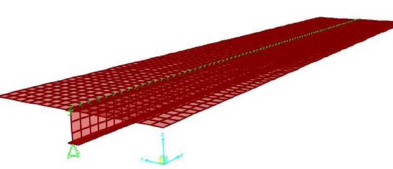
Figure 3. Numerical model – variant II (concrete slab modelled with SHELL elements)
Effects of shrinkage are simulated as a negative temperature load which is needed to cause the appropriate value of total shrinkage strain. Equivalent temperature load is shown in table 5.
Table 5. Equivalent temperature load
|
Point in time |
Shrinkage strain ε cs [10-6] |
Temperature [°C] |
|
t=7 days |
55,97 |
-5,60 |
|
t=28 days |
157,04 |
-15,70 |
|
t=1000 days |
395,29 |
-39,53 |
|
t=∞ |
413,01 |
-41,30 |
Stiffness of headed stud anchors
Equivalent stiffness of headed stud anchors is determined on numerical model shown in Figure 4. The length of the composite beam that is being modelled is equal to the longitudinal spacing of the headed stud anchors which is 146 mm. Concrete slab is modelled with SOLID elements while headed stud anchor is modelled with FRAME element. Finite element mesh 14x14x12 (X,Y,Z) is generated. Results are shown in table 6.
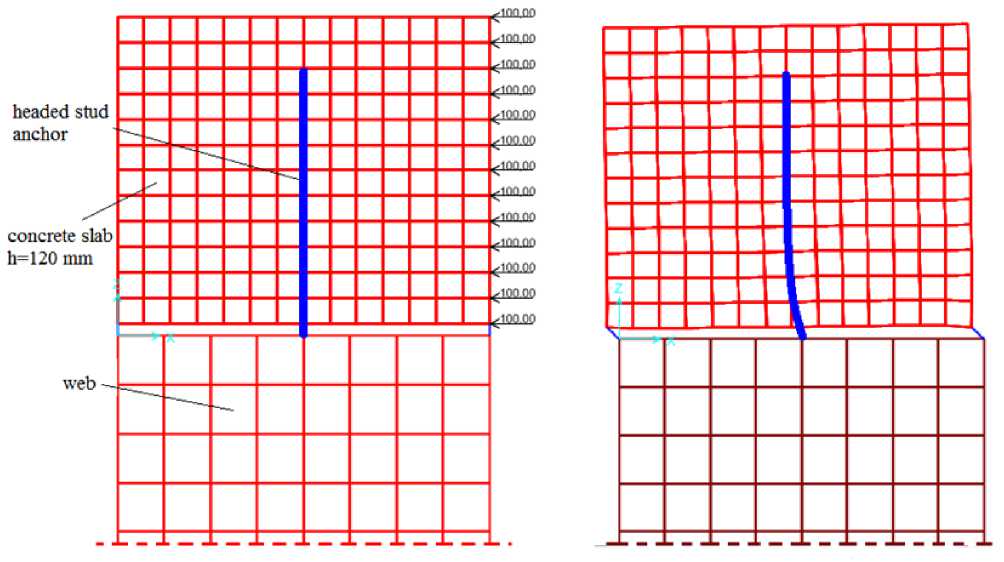
Figure 4. Numerical model for determining equivalent stiffness of headed stud anchor (left) and deformed configuration (right)
Table 6. Equivalent stiffness of headed stud anchor determined on numerical model
|
Headed stud anchors |
Equivalent stiffness [kN/m] |
|
Φ16mm |
260 010 |
|
Φ25mm |
336 500 |
Comparison of results
Below is given a comparison of analytical and numerical obtained stresses σ x , for headed stud anchors of different stiffness and for different points in time. The comparison is given for the top and the bottom flange of steel beam and is shown on diagrams log t – σ/σ analytical .
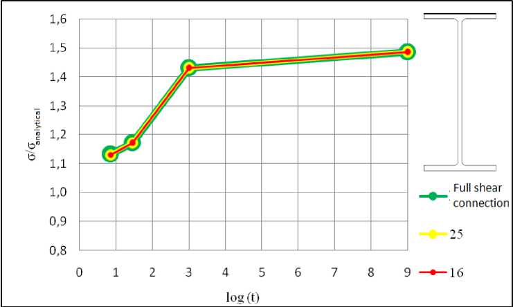
Figure 5. Comparison of numerical model with analyitical solution (top flange)
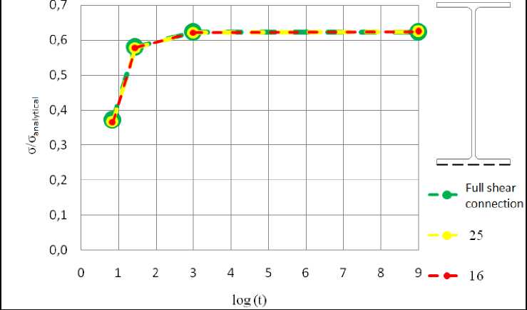
Figure 6. Comparison of numerical model with analyitical solution (bottom flange)
Список литературы Эффект усадки бетона в композитных балках
- Horvatić, D. Spregnute konstrukcije Čelik -Beton, MASMEDIA d.o.o., Zagreb, (2003), 355 p.
- EN 1992 -1 -1: 2004, (2006).
- Johnson, R.P. Composite strucutres of steel and concrete (1994) Blackwell Scientific Publications, Oxford, 98 p.
- Johnson, R.P. CSI Analysis Reference Manual (2013) Computers & Structures, pp. 158-165.
- Jasiczak, J., Szymański, P., Nowotarski, P. Computerised evaluation of the early age of shrinkage in concrete (2015) Automation in Construction, 49, pp. 40-50.
- Al-Saleh, S. A. Comparison of theoretical and experimental shrinkage in concrete (2014) Construction and Building Materials, 72, pp. 326-332.
- Afzal, S., Shahzada, Kh., Fahad, M. Assessment of early-age autogenous shrinkage strains in concrete using bentonite clay as internal curing technique (2014) Construction and Building Materials, 15, pp. 403-409.
- Maslehuddin, M., Ibrahim, M., Shameem, Ali, M.R., Al-Mehthel, M.H. Effect of curing methods on shrinkage and corrosion resistance of concrete (2013) Construction and Building Materials, 41, pp. 634-641.
- Singh, M., Siddique, R. Compressive strength, drying shrinkage and chemical resistance of concrete incorporating coal bottom ash as partial or total replacement of sand (2014) Construction and Building Materials, 68, pp. 39-48.
- Горшков А. С., Ватин Н. И. Инновационная технология возведения стеновых конструкций из газобетонных блоков на полиуретановый клей//Строительство уникальных зданий и сооружений. 2013. №8 (13). С. 20-28.
- Cusson, D., Hoogeveen, T. An experimental approach for the analysis of early-age behavior of high-performance concrete structures under restrained shrinkage (2007) Cement and Concrete Research, 37(2), pp. 200-209.
- Bentur, A., Igarashi, S., Kovler, K. Prevention of autogenous shrinkage in high-strength concrete by internal curing using wet lightweight aggregates (2001) Cement and Concrete Research, 31(11), pp. 1587-1591.
- Ватин Н.И., Синельников А.С. Большепролетные надземные пешеходные переходы из легкого стального профиля//Строительство уникальных зданий и сооружений. 2012. №1. С. 47-53.
- Klemczak, B.A. Modeling thermal-shrinkage stresses in early age massive concrete structures -Comparative study of basic models (2014) Archives of Civil and Mechanical Engineering, 14(4), pp. 721-733.
- Gilbert, R.I., Bradford, M.A., Gholamhoseini, A., Chang, Z.-T. Effects of shrinkage on the long-term stresses and deformations of composite concrete slabs (2012) Engineering Structures, 40, pp. 9-19.
- Beushausen, H., Alexander, M.G. Failure mechanisms and tensile relaxation of bonded concrete overlays subjected to differential shrinkage (2006) Cement and Concrete Research, 36(1), pp. 1908-1914.
- Cortas, R., Rozière, E.,Staquet, S., Hamami, A. Effect of the water saturation of aggregates on the shrinkage induced cracking risk of concrete at early age (2014) Cement and Concrete Composites, 50, pp. 1-9.
- Choi, P., Yun, K.K. Experimental analysis of latex-solid content effect on early-age and autogenous shrinkage of very-early strength latex-modified concrete (2014) Construction and Building Materials, 65, pp. 396-404.
- Ismail, S., Ramli, M. Mechanical strength and drying shrinkage properties of concrete containing treated coarse recycled concrete aggregates (2014) Construction and Building Materials, 68, pp. 726-739.
- Ćosić, M., Brčić, S. Iterative Displacement Coefficient Method: Mathematical formulation and numerical analyses (2013) Gradjevinar, 65 (3), pp. 199-211.
- Кишиневская Е. В., Ватин Н.И., Кузнецов В.Д. Перспективы применения нанобетона в монолитных большепролетных ребристых перекрытиях с постнапряжением//Инженерно-строительный журнал. 2009. №2. С. 54-58.
- Collins, F., Sanjayan, J. G. Strength and shrinkage properties of alkali-activated slag concrete containing porous coarse aggregate (1999) Cement and Concrete Research, 29(4), pp. 607-610.
